

Page 1

特种计算机
Embedded Computer
产品说明书
User Manual
PPC-1261
12.1″平板电脑
12.1″ Panel PC
Version: C04
Page 2
Legal Information
Warnings
Please pay attention ps within the manual void personal injury or
property losses. The tips for personal injury are indicated in warning triangles while
the tips only related to triangles. The warning tips are
listed as follows with m severe to slight.
to the ti so as to a
property losses have no warning
the hazardous scale fro
Danger
If handled carelessly, death or severe human injury will occur.
Warning
If handled carelessly, death or severe human injury might occur.
Caution
Warning triangle indi mcates that slight human injury ight occur if handled carelessly.
Note
Unexpected result or s , if not handltatus might occur ed according to the tips.
Professional Personnel
The product/system cov o
professional personnel. During operation, please
manuals, especially the safety warnings. The profess ave been trained
experiences; therefore, he/she could be aware of the risks of the
stem and avoid possible damages.
EVOC Product
Please pay attention to the following instructions:
ered by the manual can nly be handled by qualified and
follow the respective instructive
ional personnel h
and possess relevant
product/sy
Warning
EVOC product can
including the contents and
grant from EVOC fi
debugging, op
only be used according to the
the relevant technical do
components from oth required, please get the recommendation and
rst. Proper transportation, st
eration and maintenance are prerequ d
normal operation; therefore, please ensure permitted environment conditions and pay
attention to the tips within the manual.
descriptions within the manual,
cuments. If the products or
orage, assembly, installation,
isite to ensure product safety an
er companies are
Page 3

Copyright Notice
Information offered in this manual is believed to be correct at the time of printing, and
is subject to change without prior notice in order to improve reliability, design and
function and does not represent a commitment on the part of the manufacturer. In no
event will the manufacturer be liable for direct, indirect, special, incidental, or
consequential damages arising out of improper installation and/or use, or inability to
use the product or documentation.
This user manual is protected by copyright. No part of this manual may be reproduced,
stored in any retrieval system, or transmitted, in any form or by any means,
mechanical, electronic, photocopied, recorded or otherwise, without the prior written
permission from the manufacturer.
Trademarks
EVOC is a registered trademark of EVOC Intelligent Technology Co., Ltd. Other
product names mentioned herein are used for identification purposes only and may be
trademark and/or registered trademarks of their respective companies.
Warranty Terms:
The warranty on the product lasts for one year. If the user has additional requirements,
the contract signed between the two sides shall prevail.
Please visit our website:
http://www.evoc.com
for more information,
or send an email to the Technical Support Mailbox [email protected]
(International) or [email protected]
(Domestic) for consultation.
Hotline: 4008809666
Page 4

About this manual
Scope of the Manual
The manual is appropriate for EVOC PPC-1261.
Convention
The term “the PC” or “the Product” within the manual usually stands for EVOC
s
Safety instructions
ty losses or individual injury, please pay attention to the safety
arning triangle
PPC-1261.
Instruction
To avoid proper
instructions within the manual. The warnings within the manual are marked with
w
, whose existence is dependent upon the scale of the
potential hazard.
Page 5

Contents
1. Product Introduction .................................................................................................1
Examination......................................................5
ing Arm Mounting................................................7
3.2 Outer Appearance and Dimensions................................................................8
llation Dimensions .................................................................................9
3.3.1 Installation Dimensions ..............................................................................9
....................10
unding ......................................................................................10
4.3 Connecting the Device to Power .................................................................11
.........................................12
5.2 Ports for External Control............................................................................13
Port Definition................................................................................13
..............13
......................15
orts........................................................................................15
5.3.5 Network Ports..................................................................................16
5.3.6 PS/2 Keyboard/Mouse Port .............................................................16
5.3.5 VGA Port.........................................................................................17
5.3.6 Audio Port .......................................................................................17
1.1 Overview .......................................................................................................1
1.2 Product Specifications ...................................................................................1
2. Application Scheme ..................................................................................................4
2.1 Transportation................................................................................................4
2.2 Storage...........................................................................................................4
2.3 Opening the Box and Initial
3. Installation ................................................................................................................6
3.1 Mounting Method..........................................................................................6
3.1.1 Embedded Panel Snap-fit Mounting...........................................................6
3.1.2 VESA Standard Support
3.3 Insta
3.3.2 Dimensions Drawing for Hole Drilling ......................................................9
4. Device Connection..................................................................................................10
4.1 Notices before Connection ......................................................
4.2 Product Gro
5. Instructions .............................................................................................................12
5.1 Product Outline...................................................
5.3 Product
5.3.1 Standard DB9 COM ports .................................................
5.3.2 CAN Port Controller Address Setting..............................................14
5.3.3 COM Port Mode Selection ........................................
5.3.4 USB P
Page 6

Connector .............................................................................17
5.4 Operation Control........................................................................................18
6. A ce ....................................................................................19
.............................................19
6.2 Removal and Installation of the Motherboard .............................................20
g the Motherboard .......................................................................20
l and Installation of HDD ...............................................................22
7. EVOC One-Button-Recovery Operating Instructions.............................................24
e-Button-Recovery Operating Instructions..................................24
r Anti-virus Function ............................................................28
8. Appendix.................................................................................................................29
5.3.7 Power
ssembly and Maintenan
6.1 Overall Assembly ...........................................
6.2.1 Installin
6.2.2 Removal of the Motherboard....................................................................21
6.3 Remova
7.1 EVOC On
7.2 Instructions fo
8.1 Troubleshooting and Solutions ....................................................................29
Page 7

Product Introdu
ction
PPC-1261 - 1 -
1. Product Introduction
1.1 Ove
panel
PPC-
mem
PC p
(optional).
1024
and
One-Button-Recover
Deplo
rear
m
solar
maki
1.2 Pr
rview
PPC-1261 is a 12.1″ low power consumption and fanless industrial panel PC. Its front
is shaped by al-alloy and its al-alloy rear panel also serves as the heat sink.
1261 contains Intel® ATOM N455 + ICH8M chipset, Intel® low power
consumption ATOM N455 CPU (clock speed: 1.66GHz) on-board; 1G DDR3
ory and additional 1G DDR3 memory ICs on the expansion card, up to 2GB. The
rovides five USB ports, four serial ports, touch screen or tempered glass
The LCD screen can be 800x600 LCD screen with common backlight or
x768 LCD screen with LED backlight. The product features fully-sealed, fanless
super-slim design. As for software, this product supports EVOC
y, EVOC MBR anti-virus and EVOC BPI functions.
ying modular design, the product is composed of a front screen module and a
otherboard module. It is ideally suitable for such industries as rubber machinery,
energy photovoltaic and common industrial automation industries (such as paper
ng and environment protection).
oduct Specifications
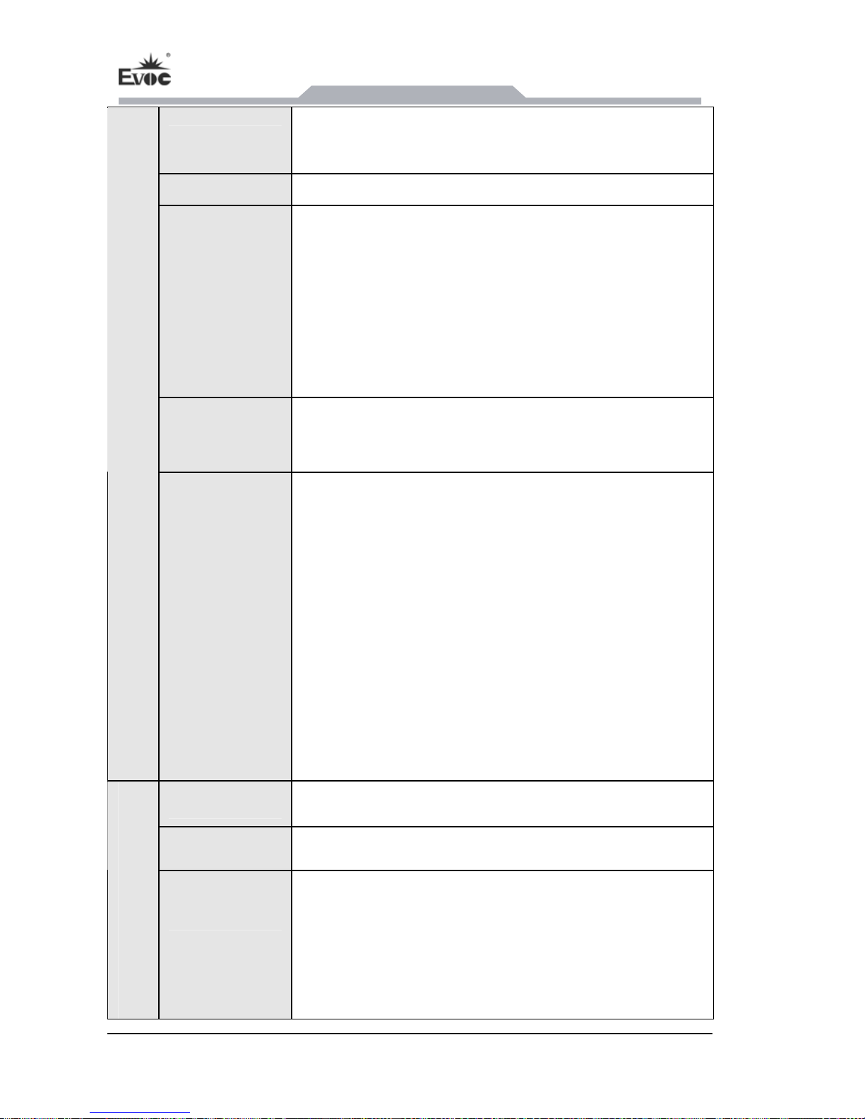
Item Definition
Microprocessor
Intel® ATOM N455 1.66GH
Chipset
Intel® ATOM N455+ Intel®ICH8M
Memory
Onboard 1GB or 2GB/DDR3/800MHz memory
Main Functional Index
Display
18bit; VGA (DB15) supports hot swap; VGA, LVDS are
Supports VGA, LVDS display; LVDS is single-channel
synchronous output.
Page 8
Product Introdu
ction
- 2 -
PPC-1261
Network
2 x 10/100/1000Mbps LAN port, LAN1 supports
Wake-On-LAN
Audio
HD standard, supporting MIC-IN/LINE-IN/LINE-OUT
LCD Screen
Features
Viewing angle (CR≥10)
LCD: 12″ TFT LCD
Resolution: 800X600 (1024X768 optional)
Luminance: 400cd/m2
Contrast ratio: 600: 1
Horizontal: 70°~70°; Vertical: 50°~60°
Touch Screen
Port type: USB
Type: 5-wire resistive
External IO
Ports
Up to six COM ports (no CAN port); all the COM
ports are RS-232 mode by default; COM1~COM4
support RS-232/RS-422/RS-485 modes;
4 x USB2.0 port;
2 x LAN port;
2 x CAN port (optional), CAN port optical-electrical
isolation;
1 x PS/2 keyboard, 1 x mouse port;
1 x VGA port;
1 x LINE-IN, 1 x LINE-OUT, 1 x SPEAKER-IN
Dimensions
320mm (L) x 242mm (W) x 70.6mm (H);
Weight
5 Kg;
Main Performance Index
Temperature
Operating temperature: -10℃~50℃
Extendable Operating Temperature: -30℃~70℃
Storage temperature: -20℃~60℃
Extendable Storage Temperature: -40℃~85℃
Operating Wet & Humidity: 40℃, 95% RH.
Page 9

Product Introduction
PPC-1261 - 3 -
Humidity
5 %~95% (non-condensing)
EMC
GB9254-2008, class A;
Limits of immunity are compliant with the thresh
Limits of radio disturbance are compliant with
old
of GB/T 17618-1998.
Reliability
MTBF≥10000h
MTTR≤0.5h
Safety
Meets basic requirements of GB4943.
Protection
Grade
Screen surface complies with IP65 grade.
Mechanical
and
Environmental
Adaptability
Anti-shock: 15g/11ms. Half-sine wave, three times
for each of the three axes.
Anti-vibration: 5-19Hz/1.0mm amplitude;
19-200Hz/1.0g, three axes.
Power
Features
Power consump
Input voltage/current: 9~30VDC/3.5~1A;
Power consumption of
the PC: 18W (standby);
tion of the PC: 28.7W (burnintest
100%).
Software
Function
overy function (please refer
etailed information);
refer to
d
CD).
EVOC One-Button-Rec
to Chapter 7 of the manual for d
EVOC MBR anti-virus function (please
Chapter 7 of the manual for detailed information);
EVOC BPI function (please refer to the motherboar
user manual in the
Page 10

Application Sch
eme
- 4 -
PPC-1261
2. Applic hemation Sc e
2.1 Transport
Well-packaged products are suited for transportation by truck, ship, and plane. During
transportation, products During
transship without protection from the
atmospher rted together with inflammable,
explosive and corrosive be exposed to rain, snow
and liquid substances an
2.2 Storage
Products should
temperature should be 0°C
the warehouse, there should oducts, and
corrosive hanical vibration, shock and strong
magnetic fie
and 50cm away from indow and air inlet.
Caution!
ation
should not be put in open cabin or carriage.
ping, products
ic condition
should not be stored in open air
s. Products should not be transpo
substances and are not allowed to
d mechanical force.
be stored in package box when it is not used. And warehouse
~ 40°C, and relative humidity should be 20% ~ 85%. In
be no harmful gas, inflammable, explosive pr
chemical pro
ld inter
ducts, and strong mec
ference. The package box should be at least 10cm above ground,
wall, thermal source, w
Risk of destroying the device!
When shippin
tempera n. re no water
on ) is on the surface or interior of the device. If
densation is formed on the device, please wait for over twelve hours before
necting the
g the PC in cold weather, please pay attention to the extreme
ture variatio Under this circumstance, please make su
drop (c
con
con
densation formed
device.
Page 11

Application Scheme
PPC-1261 - 5 -
2.3 Open x an
Opening the Box
Please pay attention to the box:
● Do not discard th
material for re-transportation.
● Please keep the documentation at a safe place. The documentation, which is a part
of the d ired for initial device debugging.
● When doing the initial examination, please check whether there are distinct
damages t
● Please of the
independe red accessories. Please contact the customer service when any
unconf
ing the Bo d Initial Examination
the following issues when opening
e original packing material. Please keep the original packing
evice, is requ
o the device caused during the transport.
check whet
ntly orde
her the delivery contains the intact device and all
ormity or transportation damages occur.
Page 12
Installation
- 6 -
PPC-1261
3. Installation
3.1 Mounting Method
3.1.1 Embedded Panel Snap-fit Mounting
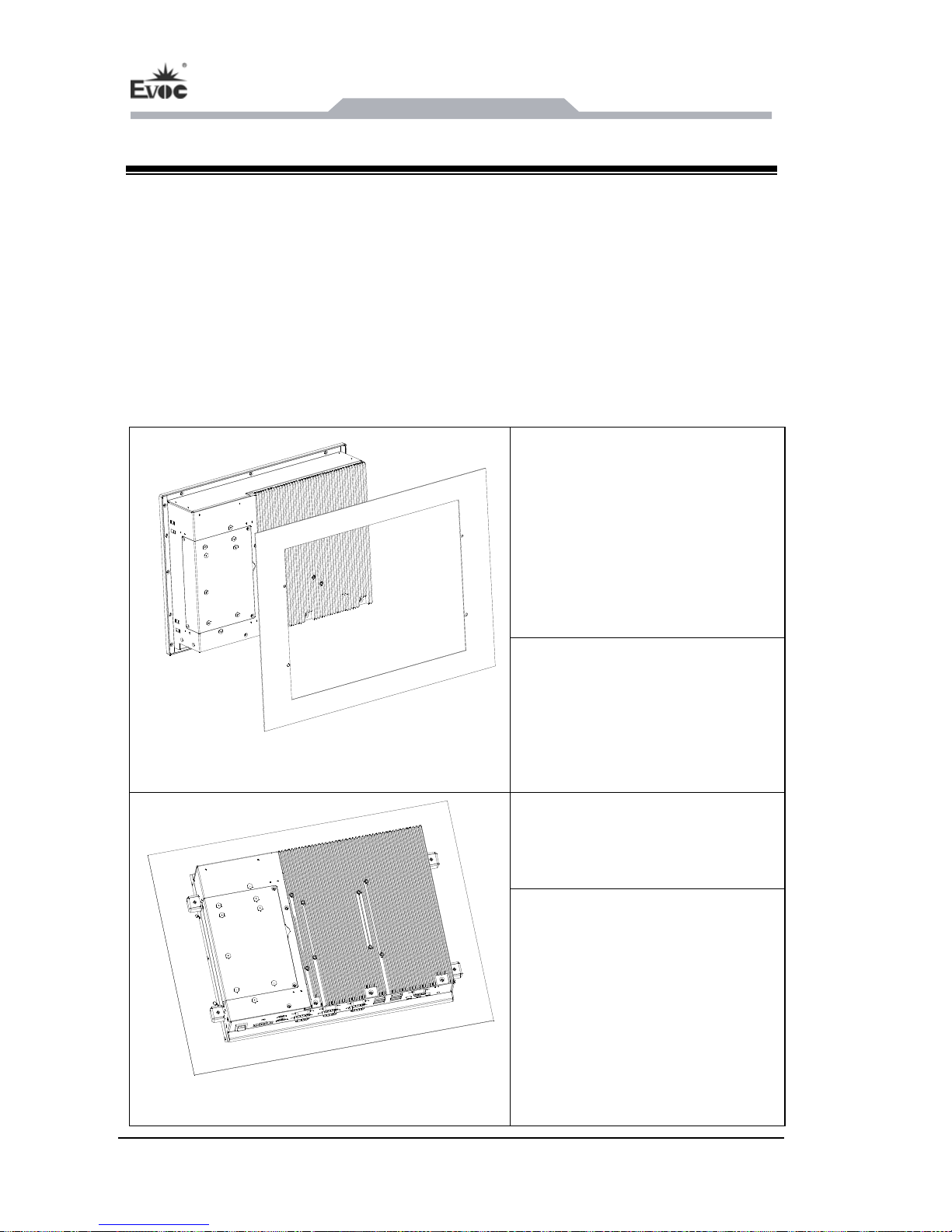
Step 1: Mount the PC on the wall
by the holes already drilled, as
□19″ Rack Mount □Desktop ■Embedded Panel
□Wall Mount ■VESA Standard Arm □Portable
□Others___________
shown in the left picture (b
efore
installation, remove the rubber
plug in the holes).
Note: as for the installation
requirements, please see the table
below.
Step 2: Fix the mounting bracket
by screws (spec.: M4*10)
the PC.
Note: The mounting bracket and
the screws are the accessories of
Page 13
Installation
PPC-1261 - 7 -
Material Hole diameter Mounting
Diameter:
Depth: 60mm
Peg: diameter 8mm; length
Screw: diameter 4 mm; length
Concrete
8mm 50mm
50mm
Plasterboard (minimum
thickness: 13mm)
14mm
length: 50 mm
Diameter:
Plaster support: diameter 4 mm;
Metal (minimum thickness:
Diameter:
Metal screw: M 4: diameter
2mm)
5mm
4mm; length: 15mm
Warning
Please make sure the wall or ceiling shall be able to support at least four times the
total weight of the PC. (including cabinet bracket and additional expansion modules)
3.1.2 VESA Standard Supporting Arm Mounting
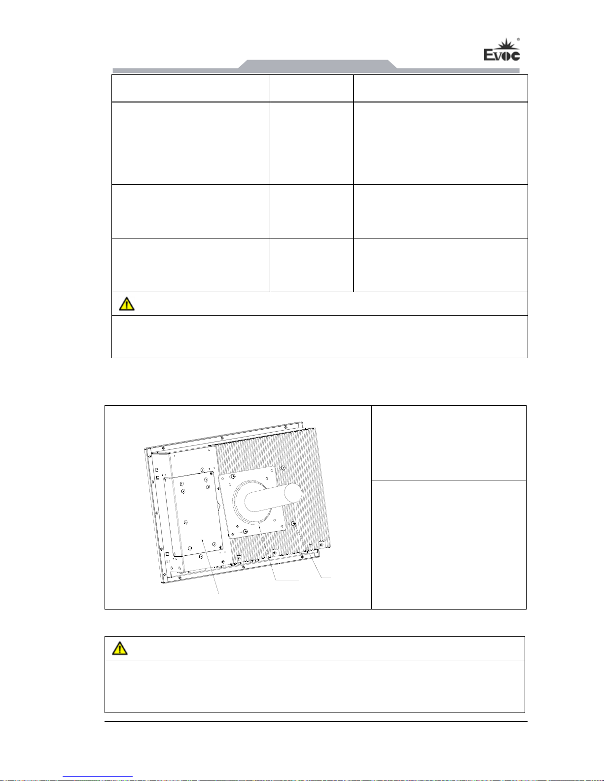
Step: Use screws to fix the
PC on the supporting arm, as
shown in the left picture.
Screw
VESA supporting
bracket
PC
Note: During the installation,
please use screws enclosed
with the PC or select screws
according to the instructions
of the manual.
War ni ng
The weight bearing capacity of VESA arm shall be at least twice the weight of the
PC.
Page 14
Installation
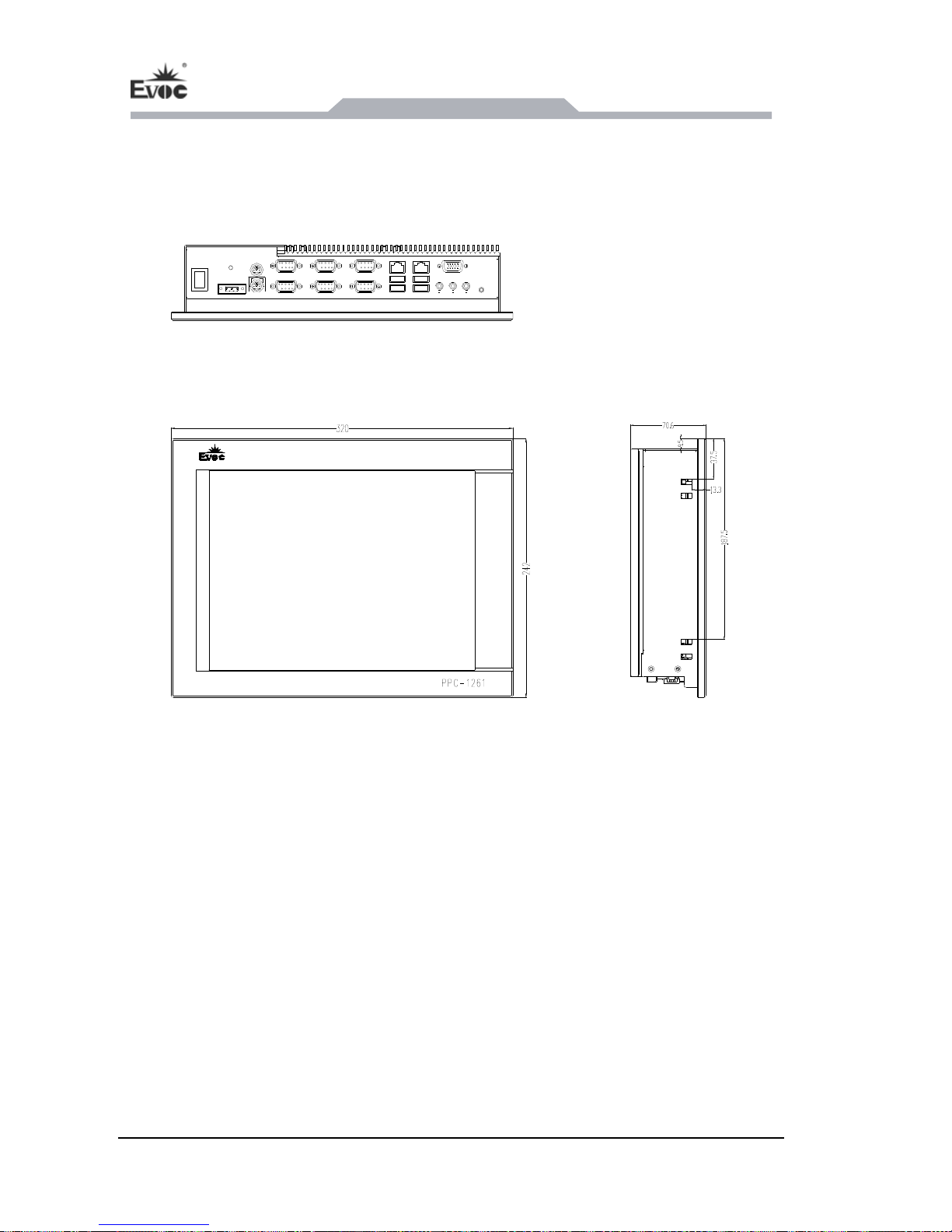
- 8 -
PPC-1261
3.2 Outer Appearance and Dimensions
Unit: mm
Page 15
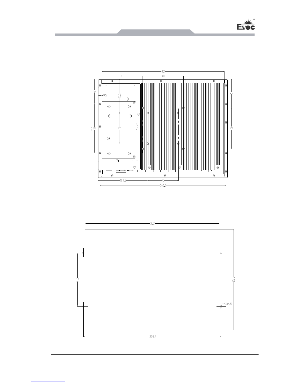
Installation
PPC-1261 - 9 -
3 lation Dimensions
3 lation Dimension
.3 Instal
.3.1 Instal s
Unit: mm
3.3.2 Dimensions Drawing for Hole Drilling
Unit: mm
Page 16
Device Connection
- 10 -
PPC-1261
4. Device Connection
4.1 Notices before Connection
Warning
The connected or built-in peripherals with opposite polarities are not allowed.
Warning
The device only operates when connecting with grounded power. No operation is
allowed when the device power is ungrounded or only impedance is grounded.
Warning
Rated voltage of the device in use shall be in accord with power feature of the
product.
Note:
Only the peripheral devices approved for industrial application can be used. When
operating the PC, hot swappable IO modules (USB) can be used. The IO devices
without hot swap function can only be connected when the PC is powered off.
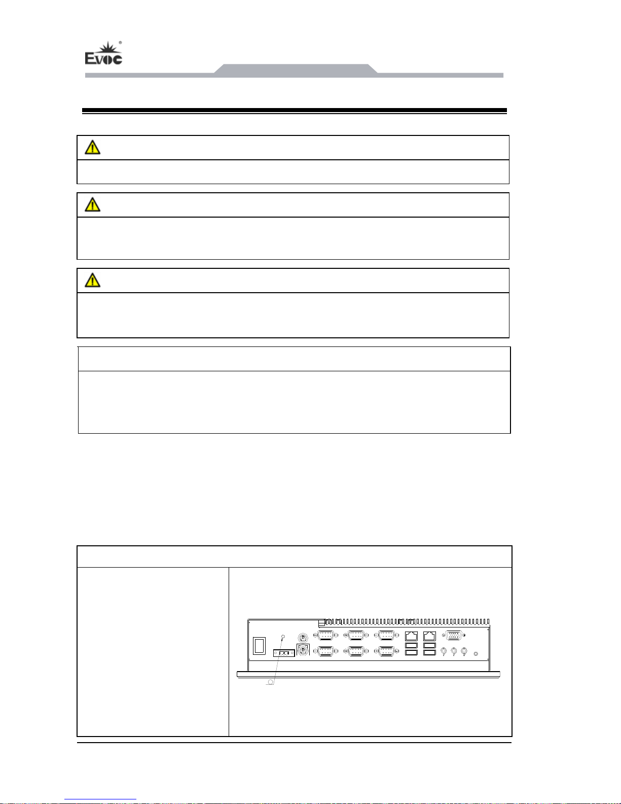
4.2 Product Grounding
Low impedance ground connection is more helpful to release the interference
produced by the external cables, the si or the cables connecting the IO
module to the grounding system.
Ground Terminals
gnal cables
The equipotential bonding
terminal ① on the device
shall be connected with the
cabinet installed with the
PC or the central grounding
busbar on the device. The
minimum cross section area
of the cable shall be no less
1
Page 17
Device Connection
PPC-1261 - 11 -
than 5mm
2
, and the
maximum ground
resistance shall be no more
than 0.1Ω.
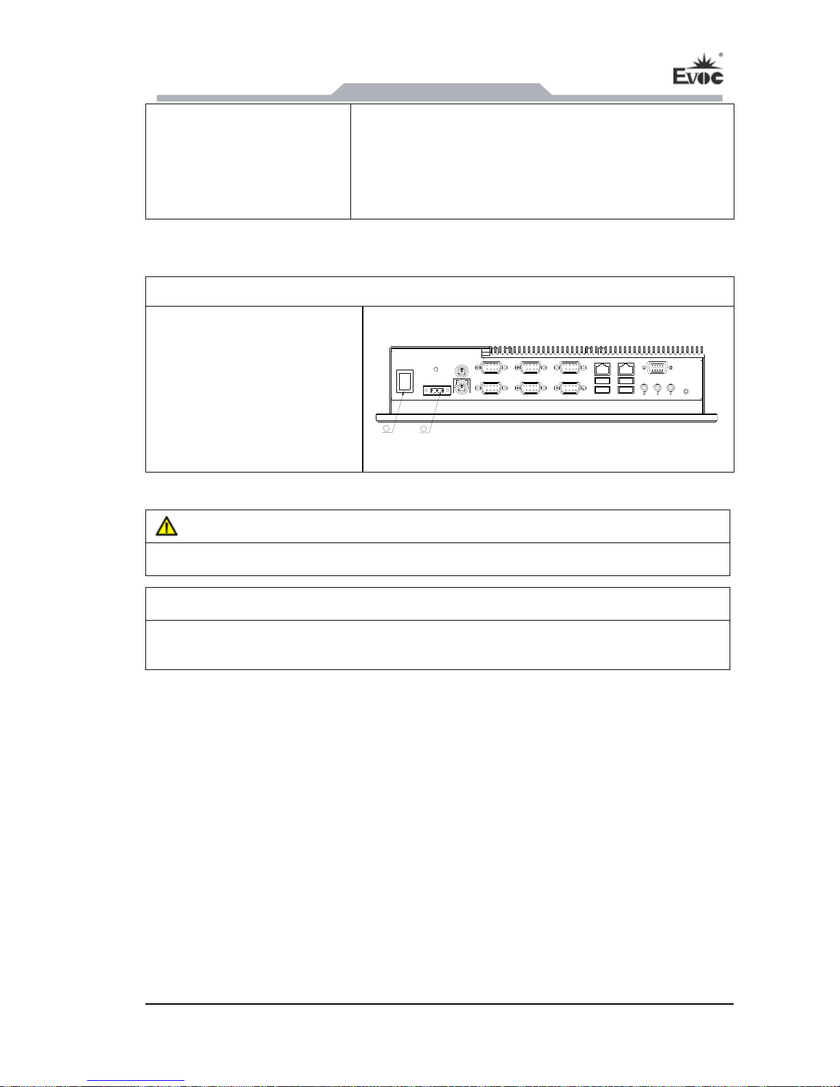
4.3 Connecting the Device to Power
Steps to connect the device to power:
Connect the power cable to
the socket ②, and connect
the power switch ①.
1
2
Danger
Disconnect the power source and data ca lightning storm. ble during a
Attention
The PC is completely isolated from the power supply only by disconnecting the
power connector.
Page 18
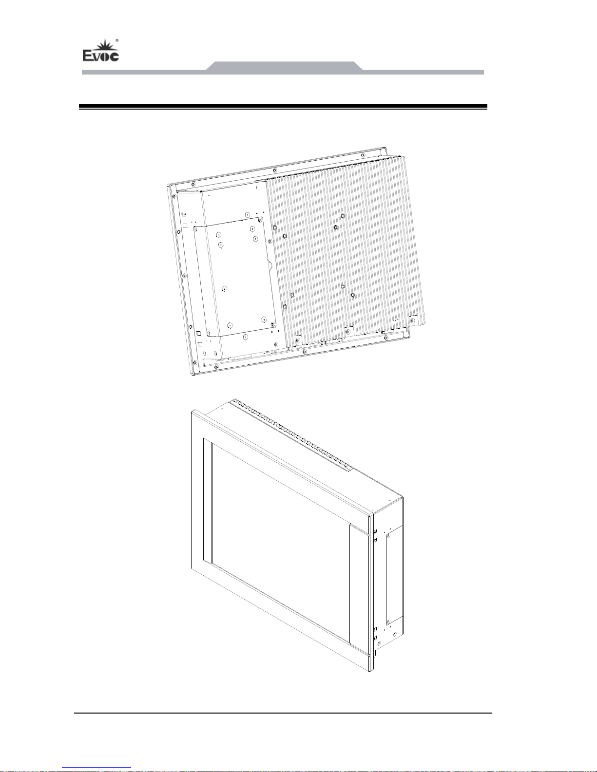
Instructions
- 12 - PPC-1261
5. Instructions
5.1 Product Outline
Page 19
Instructions
PPC-1261 - 13 -
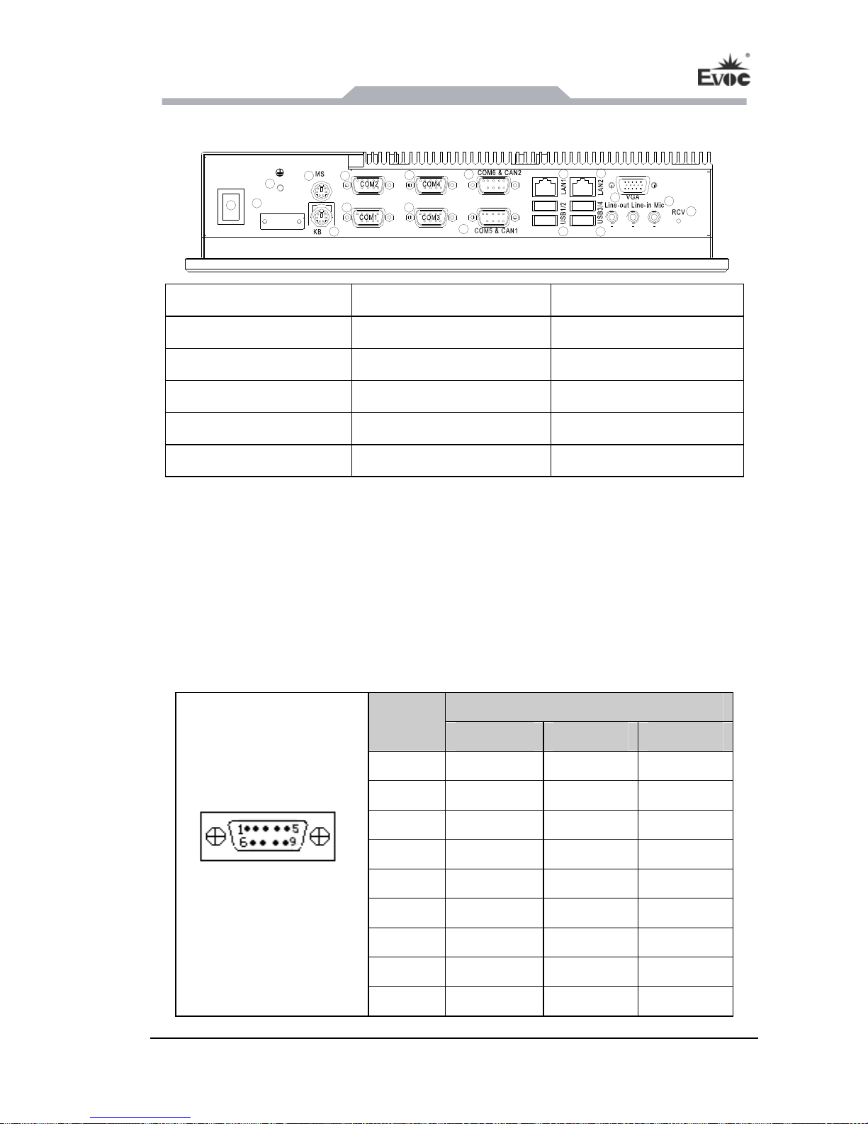
5.2 Ports for External Control
DC 9~30 IN
1
2
3
4
6
9
11
14
15
16
17
18
7
8
10
12
13
POWER SW
5
1. Power switch 2. Ground screw 3. Power input connector
4. MS 5. KB 6. COM2
7. COM1 8. COM4 9. COM3
10. COM6 or CAN2 11. COM5 or CAN1 12. LAN1
13. LAN2 14. USB1/2 15. USB3/4
16. VGA 17. Audio 18. RCV
5.3 Product Port Definition
5.3.1 Standard DB9 COM ports
The carrier board provides six DB9 ports (EF-EIO-028PPC-COM provides six COM
orts, EF-EIO-028PPC-CAN provides four COM ports + two CAN ports). The ports
. J7 (COM1, COM2) and J8 (COM3, COM4) support
p
are double-layer combo socket
RS-232/RS-422/RS-485 modes. Their pin definitions are as follows:
Signal Name
Pin
RS-232 RS-422 RS-485
1 DCD# TXN DATA-
2 RXD TXP DATA+
3 TXD RXP NC
4 DTR# RXN NC
5 GND GND GND
6 DSR# NC NC
J7, J8 (COM1~COM4)
7 RTS# NC NC
8 CTS# NC NC
9 RI#
NC NC
Page 20
Instructions
- 14 - PPC-1261
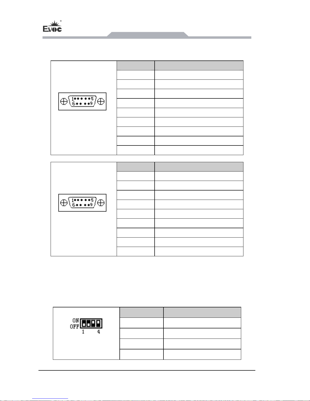
J14 is a duplex port. J14 (COM5
J14 (CAN1, CAN2, EF-EIO-028
PPC-C
, COM6, EF-EIO-028PPC-COM) supports RS-232 or
AN). Their pin definitions are as follows:
Pin Signal Name
1 DCD#
2 RXD
3 TXD
4 DTR#
5 GND
6 DSR#
7 RTS#
8 CTS#
J14 (COM5,COM6)
9 RI#
Pin COM Signal Name
1 NC
2 CAN_L
3 CAN_GND
4 NC
5 CAN_GND
6 CAN_GND
7 CAN_H
J14
8 NC
(CAN1,CAN2)
9 CAN_VCC(5V)
Note: CAN ports are optical-electrical isolation port. Their signals, GND and
VCC are all isolated.
5.3.2 CAN Port Controller Address Setting
This board provides two CAN ports. Their controller address is set by SW1 (on the
back of the board). The default setting is 1100, address 300.
Code Bit Status
1
ON
2
ON
3
OFF
SW1
4
OFF
Page 21
Instructions
PPC-1261 - 15 -
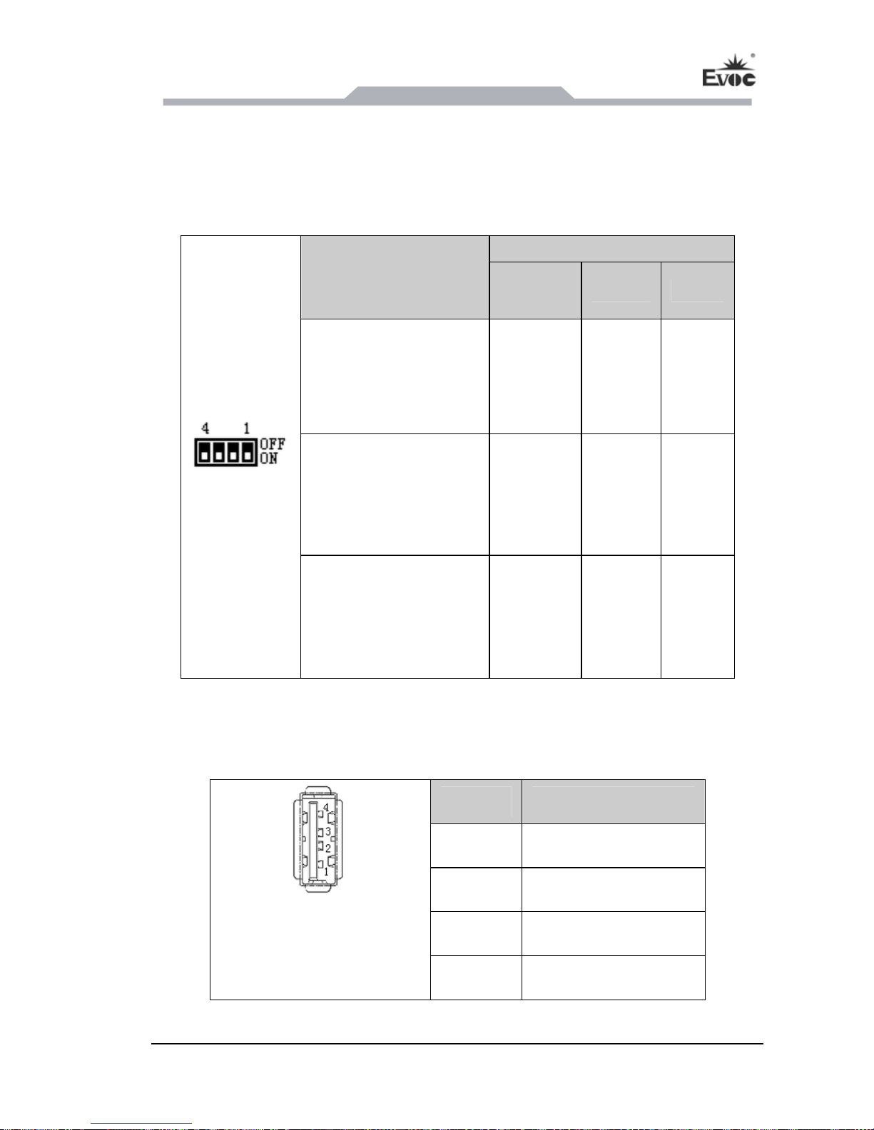
5.3.3 COM Port Mode Selection
COM1~COM4 are fully compliant with RS-232/RS-422/RS-485 (on the back of the
board). RS-232/RS-422/RS-485 mode selection can be realized by SW3~SW14
jumper setting. The setup method is as follows:
Mode Selection
Pin Setting
RS-232
RS-422 RS-485
(default)
SW3/SW6/SW9/SW12
1 ON
2 OFF
3 OFF
4 NC
1 OFF
2 OFF
3 ON
4 NC
1 OFF
2 ON
3 OFF
4 NC
SW4/SW7/SW10/SW13
1 ON
2 OFF
3 ON
4 OFF
1 OFF
2 ON
3 OFF
4 ON
1 OFF
2 ON
3 OFF
4 ON
SW3~SW14
SW5/SW8/SW11/SW14
1 ON
2 OFF
3 ON
4 OFF
1 OFF
2 ON
3 OFF
4 ON
1 OFF
2 ON
3 OFF
4 ON
Note: Under RS-485 mode, the data send/receive direction is automatically controlled.
5.3.4 USB Ports
Pin Signal Name
1
+5V
2
USB_Data-
3
USB_Data+
J5 (USB1, USB2)
J6 (USB3, USB4)
USB5
4
GND
Page 22
Instructions
- 16 - PPC-1261
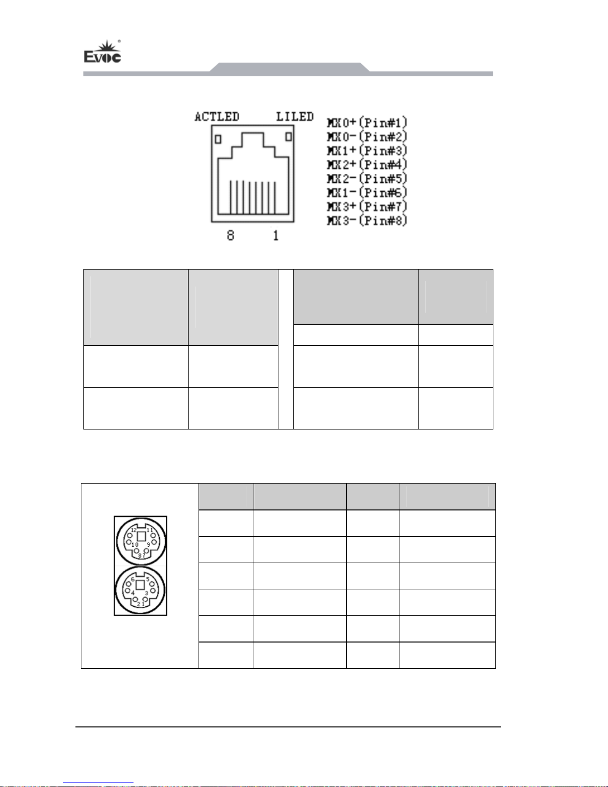
5.3.5 Network Ports
J5 (LAN1), J6 (LAN2)
LILED
(two colors:
orange/green)
Network
Speed
ACTLED
Network
(Single color:
Activity
Green 1000Mbps
green)
Flash
Data being
transmitted
Orange 100Mbps
Off
No data being
transmitted
Off 10Mbps
5.3.6 PS/2 Keyboard/Mouse Port
Pin Signal Name Pin Signal Name
1 KB_DATA 7 MS_DATA
2 NC 8 NC
3 GND 9 GND
4 +5V 10 +5V
5 KB_CLK 11 MS_CLK
KM1
6 NC 12 NC
Page 23
Instructions
PPC-1261 - 17 -
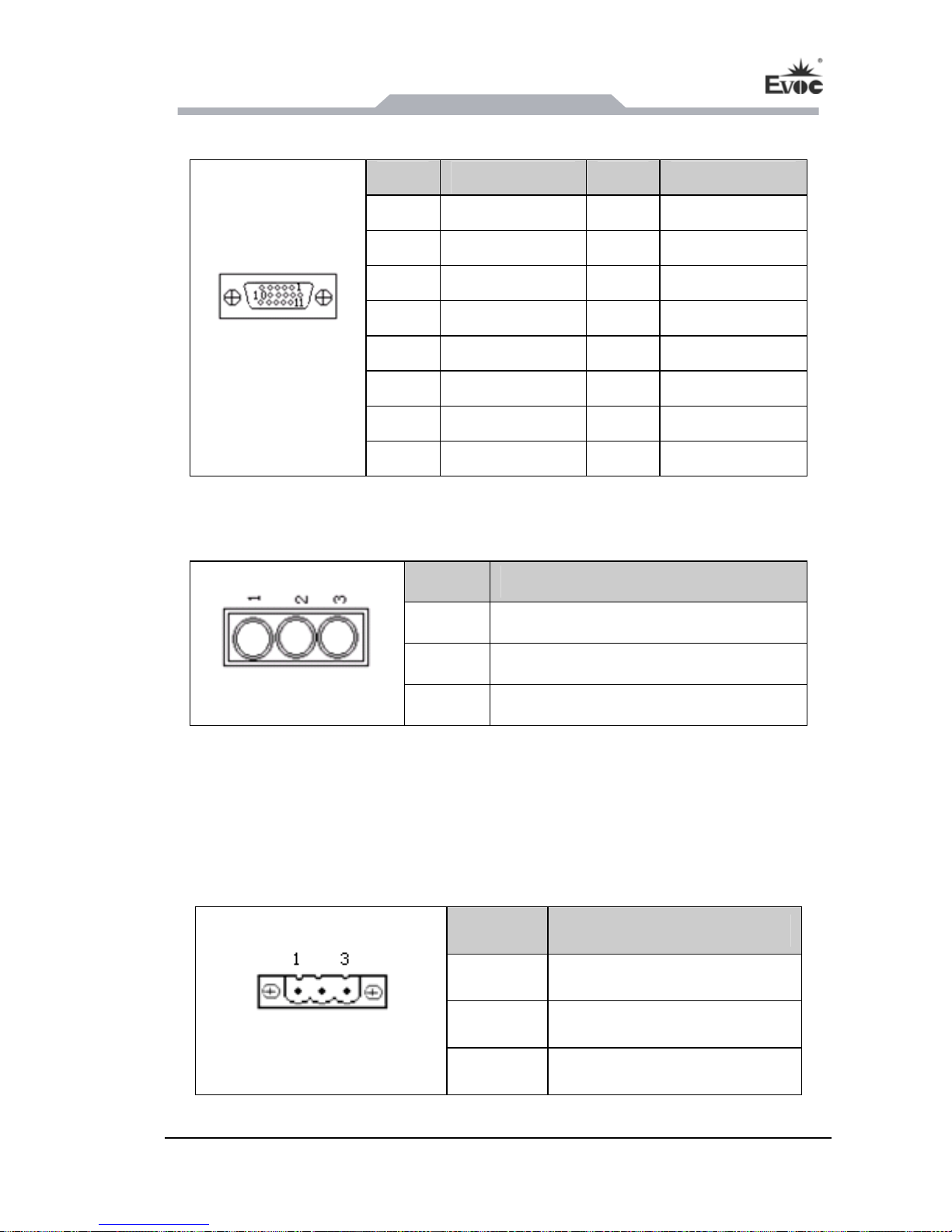
5.3.5 VGA Port
Pin Signal Name
Pin Signal Name
1 Red 2 Green
3 Blue 4 NC
5 GND 6 GND
7 GND 8 GND
9 NC 10
GND
11 NC 12 DDCDATA
13 HSYNC 14 VSYNC
VGA1
15 DDCCLK
5.3.6 Audio Port
Pin Signal Name
1 LINE_OUT (Green)
2 LINE_IN (Blue)
AUDIO1
3 MIC_IN (Red)
5.3.7 Power Connector
The carrier board provides one 3P horizontal in (pi mm),
which supports single power supply ith v e inpu ~
pin definitions are as follows:
Phoenix term al socket tch: 5.08
input, w oltag t range: 9V 30V DC. Its
Pin Signal Name
1 GND
2 NC
PWR1
3 VCC
Page 24
Instructions
- 18 - PPC-1261
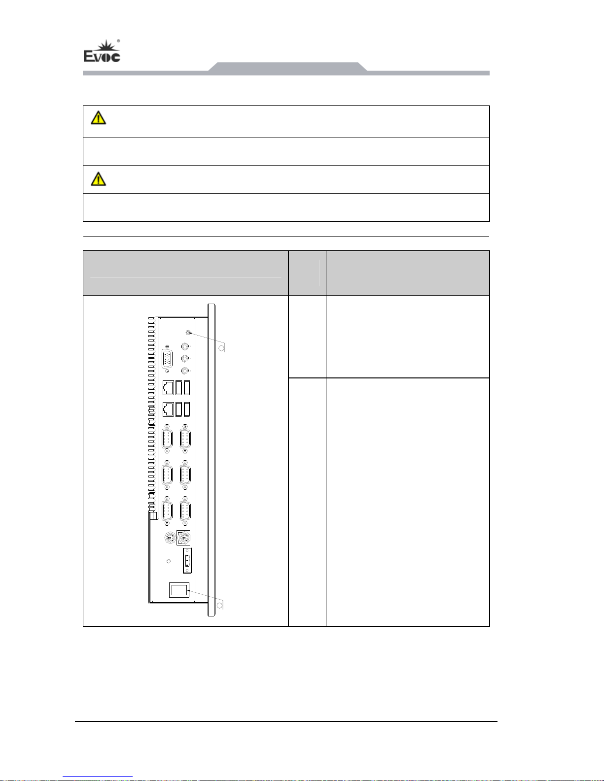
5.4 Operation Control
Warning
The On/Off button signal will not disconnect PC power supply!
Caution
When the PC executes hardware res ta may be lost. et, da
Control Button
Item Description
②
T on used
to power e PC.
he On/Off
switch butt
on th
1
2
②
wait for the
One-Button-Recovery button.
After ower-on
switc ompt will
appear D screen to
indicate One-Button-Recovery
fun SW2 to
One-Button-Recovery
terface. As for how to realize
S Function of this
manual.
pressing the p
h button, a pr
on the LC
ction. Then press
in
this function, please refer to
the BIO
Page 25
Assem
bly and Maintenance
PPC-1261 - 19 -
6. Assembly and Maintenance
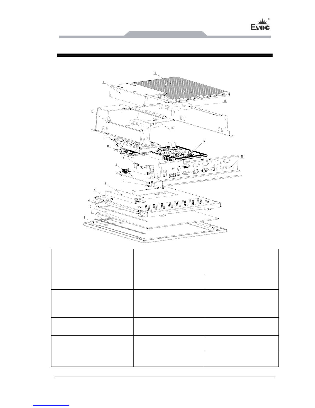
6.1 Overall Assembly
1.
screen
Al-alloy front panel 2. Water-proof strip 3. Tempered glass or touch
4. Silicone foam 5. LCD assembly 6. Backlight board
7. Touch screen control panel 8.IO board 9. Software dog bracket
module
10.CF card (or 1.HDD (or CF card) ody HDD) 1 12. Chassis b
13. HDD cover 4. Chassis top cover 1 15. Motherboard heat sink
16. Power supply heat sink 17. Motherbo 18. IO bracket ard
Page 26
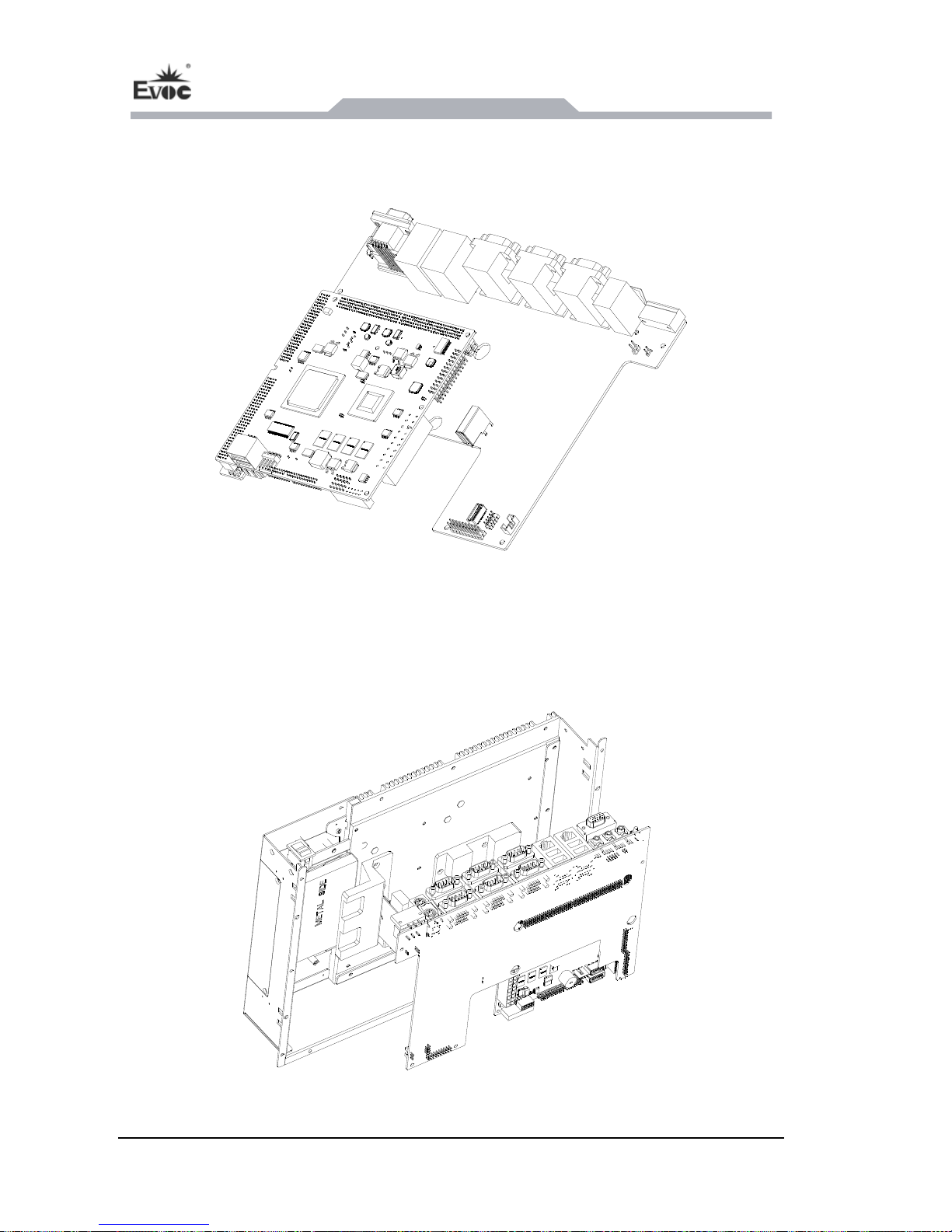
Assembly and Maintenance
- 20 - PPC-1261
6.2 Removal and Installation of the Motherboard
6.2.1 Installing the Motherboard
Firstly, assemble the mot the IO board following the above picture, then
install th mbled PCB part ight position i the chassis; f en
it with screws. Note: During the installation process, anti-static gloves must be worn!
herboard with
e asse onto the r nside inally fast
Page 27
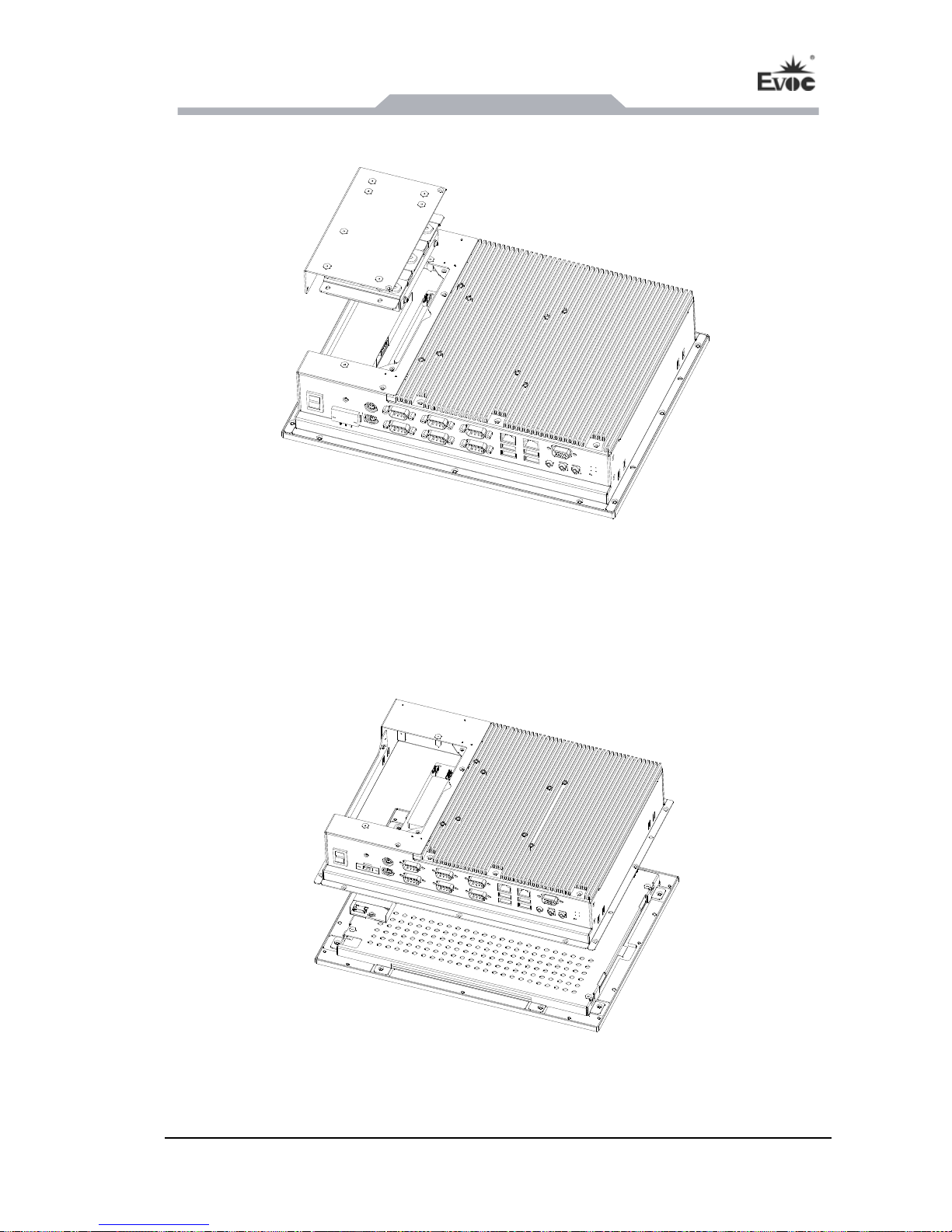
Assem
bly and Maintenance
PPC-1261 - 21 -
6.2.2 Removal of the Motherboard
1. First, remove the HDD or CF card module following the above picture, then pull
out the LCD cable, backlight boar le, touch control s cable only
exists when there is a touch screen) from the IO boar
2. Take apart the panel from the chassis body as per the fo e;
d cab panel cable (thi
d;
llowing pictur
Page 28
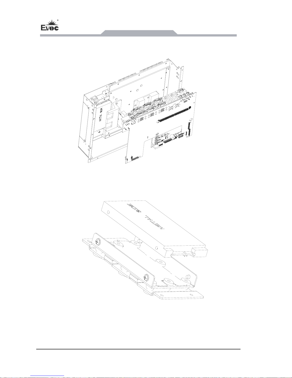
Assembly and Maintenance
- 22 - PPC-1261
3. Remove the IO board and motherboard as
sembly from the chassis rear cover, as
shown in the picture below;
4. Finally, separate the IO board from the motherboa
6.3 Removal and Installation of HDD
rd assembly.
1. First assemble the HDD onto the HDD bracket, as shown in the above picture. Then
fix it with the HDD cover lock and install them into the right position as per the
following picture (CF card is to be directly installed on the HDD cover);
Page 29
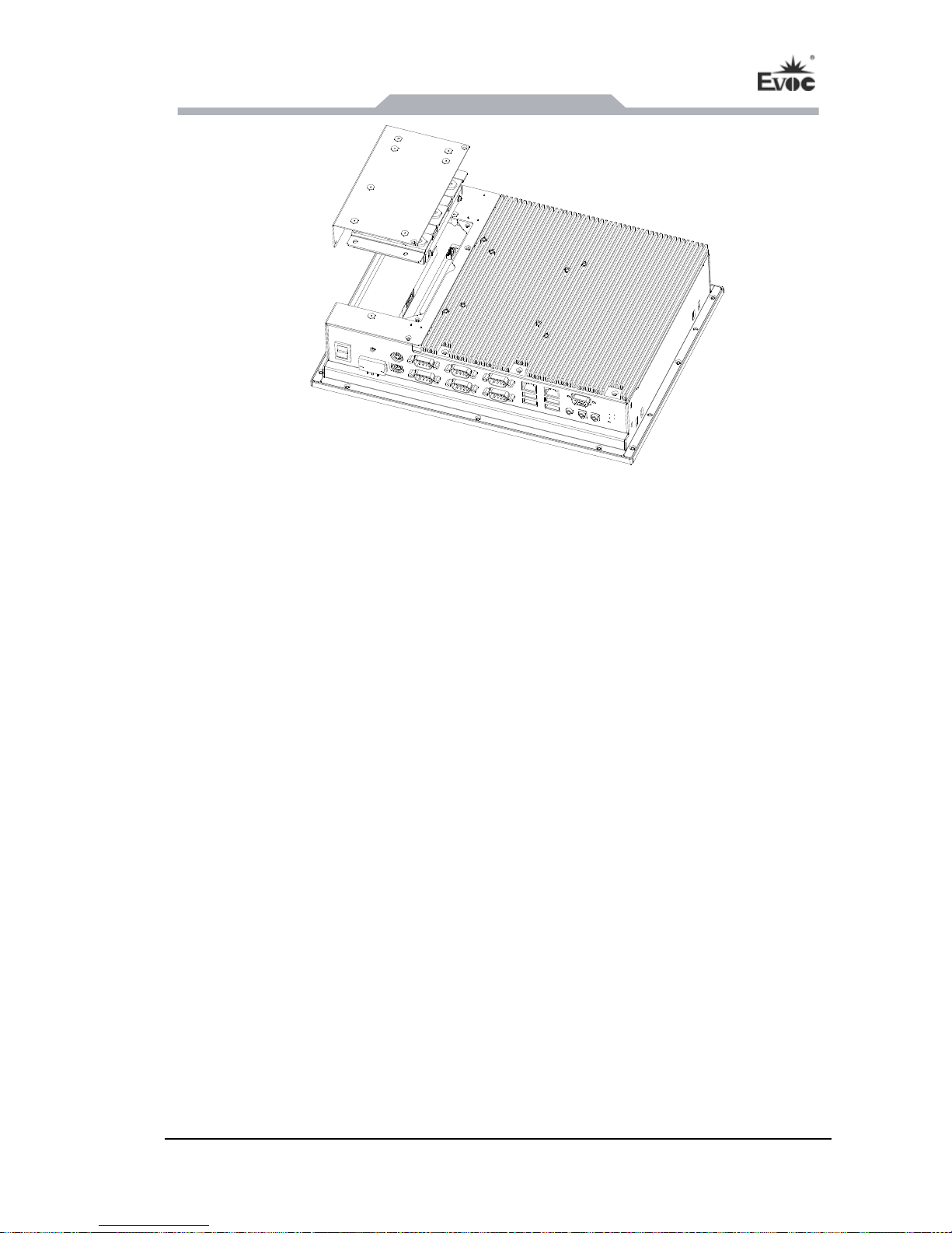
Assembly and Maintenance
PPC-1261 - 23 -
2. Follow the above picture to dismantle the HDD or CF card module from the chassis,
then separate the HDD or CF card from its bracket.
Page 30

EVOC One-Button-Recovery Operating Instructions
- 24 - PPC-1261
7. EVOC One-Button-Recovery Operating Instructions
7.1 EVOC One-Button-Recovery Operating Instructions
EVOC one-key recovery functions supports to back up and recover the data in various
file systems (FAT32/NTFS/EXT2/EXT3/EXT4). The backup configuration is quite
flexible; please specify different configurations according to actual requirement. The
following instructions only refer to the default settings. The function supports
keyboard or “RCV” button operation; the “RCV” button is configured on PPC-1261.
A. Instructions
1. The storage devices described here only refer to the devices supported by
EVOC boards or EVOC PCs, including IDE/SATA hard disks, CF cards or
DOM disks, etc (USB storage devices are currently unsupported).
2. When only one storage device is installed in PC, it will back up the data in the
first partition of the storage device to the last partition, or recover the backup
partition of the primary disk in the last partition of the secondary disk; while the
default recovery mode is to restore the backup image files in the last partition of
the secondary disk to the first partition of the primary disk.
When both CF card and hard disk are installed in PPC-1261, the CF card is set
as the primary disk of the PC in default and the last hard disk is set as the
secondary disk of the PC. When only two hard disks are installed in PPC-1261,
the first hard disk is set as the primary disk of the PC in default and the last hard
disk is set as the secondary disk of the PC.
4. In PPC-1261, each storage device shall have two partitions, to ensure the
successful operation of system backup and recovery.
5. The file system in the partition of the backup disk can differ from that of the
recovery disk; however, the file systems exceeding FAT32 /NTFS /EXT2 /EXT3
/EXT4 are unsupported.
image files in the last partition of the storage device to the first partition.
3. The PC can supports up to three storage devices at the same time: one storage
device is set as the prime system disk while the last storage device is set as the
secondary system disk. The default backup mode is to save the data in the first
Page 31

EVOC One-Button-Recover
y Operating Instructions
PPC-1261 - 25 -
6. Please make sure the backup image files are ready when implementing recovery
for the first time (that is to say, the data shall be backed up following the
foresaid steps). Otherwise, the recovery is invalid.
7. The backup and recovery of the Windows operating system other than Microsoft
Windows7 is currently unsupported.
B. Operating Steps:
1. Enable or disable EVOC One-key Recovery Function.
Press “DEL” key to enter the BIOS Setup interface after the power-on interface
appears.
(1) Find the BOOT option in BIOS Setup interface, set the EVOC Backup
option to [Enable] or [Disabled] the EVOC One-key Recovery Function.
(2) As for the implementation on SATA hard disk, please set the operating
E
to
f the hard disk for EVOC
em backup
or recovery.
(3) Press “F10” to save and reboot.
2. Enter system backup & recovery interface.
When EVOC One-key Recovery function is enabled, it will prompt “Please Press
button <RCV> for System Recovery within 3 Seconds!!”; at that time, press the
button <RCV> at the back of the panel PC within 3 seconds and the system will
enter system backup and recovery interface.
Note: There are two kinds of silk screen printing for the key of
One-Button-Recovery: one is a sign “←”, the other is “RCV”. The two kinds
of silk screen printing are consistent with each other.
3. Implementing system backup
After entering the system backup & recovery interface, it will r
whether to implement system backup. If the user chooses to skip system backup,
then it will enter system recovery directly. The operating system will display the
mode of the SATA hard disk first. Enter Advanced->ID
Configuration->set ATA/IDE Configuration to Enhanced, which is
improve the backup and recovery speed o
One-key Recovery Function. Please restore the setting after syst
inquire the use
Page 32

EVOC One-Button-Recovery Operating Instructions
- 26 - PPC-1261
following information:
Welcome to EVOC-Backup-System
Website: http://www.evoc.com
*************************************************************"
* [save] backup the system
* [restore] restore the system
"*************************************************************"
If you want to save image,please press the <RCV> key or type "save"(default:restore)!
3.1 Enter save and press Enter or “RCV” button within 10 seconds, system backup
will be implemented and the following information will appear:
save (Note: it is the command input line and the following information is
displayed after inputting the command and pressing Enter to confirm)
Save NTFS
Syncing…
10% completely
When the operating is completed, the following information will appear and the
system will reboot after 5 seconds.
Save system success! After 5 seconds to reboot!
Note:
1) It is normal if the progress bar is not moving for around 1 minute; the system is
operating at the background. Please wait with patience.
2) The time needed for system backup is around 2~10 minutes, which is dependent
upon the size of the system disk.
3) If the system prompts “Save system success!”, it indicates that the system has
been backed up successfully and the system will reboot after 5 seconds.
4) After rebooting, set the Boot option in BIOS to disable EVOC One-key
3
be implemented. Enter restore and press Enter, the following information will
Recovery Function.
.2 Enter restore and press Enter within 10 seconds, system recovery operation will
appear:
Page 33

EVOC One-Button-Recover
y Operating Instructions
PPC-1261 - 27 -
restore (Note: it is the command input line and the following information is
displayed after inputting the command and pressing Enter to confirm)
RestoreNTFS
10% completely
Syncing…
When the operating is completed, the following information will appear and the
system will reboot after 5 seconds.
Restore system success! After 5 seconds to reboot!
Note:
1) It is normal if the progress bar is not moving for around 1 minute; the system is
operating at the background. Please wait with patience.
3) If the system prompts “Restore system success!”, it indicates that the system has
been recovered successfully and the system will reboot after 5 seconds.
4) After rebooting, set the Boot option in BIOS to disable EVOC One-key
Recovery Function.
3.3 If no character or invalid characters are input within 10 seconds, system
recovery will be implemented, which is the same as inputting “restore”.
4. Reference Data from Experiment
The table below lists the data from EVOC one-key recovery function test, which are
used for reference only.
Table 1 Value from EVOC One-key Recovery Function Test
2) The time needed for system backup is around 2~10 minutes, which is dependent
upon the size of the system disk.
Page 34

EVOC One-Button-Recovery Operating Instructions
- 28 - PPC-1261
Partition for Backup Object
Partition for Image
Saving
NO.
Backup Recovery Image
Size
Actual
Compression
Ratio
Operating
System
Total Used File Partition
Time Time
(Standard)
Capacity Space System Capacity
1
Windows xp
Professional
32bit
Chinese
20975MB 4401MB NTFS 278GB
10 min.
10 sec.
2 min. 25
sec.
4.09GB
93%
2 0975MB 5217MB NTFS 213G
11 min. 2 min. 56
4.85GB
93%
Windows xp
Professional 2
64bit English
38 sec. sec.
3
Fedora 14/
2.6.35/32Bit
10486MB 886M EXTFS 10G 34 sec. 27 sec.
808MB
91%
7.2 Instructions for Anti-virus Function
The EVOC MBR anti-virus function is integrated in BIOS, which is well protected
from damage from other software (including virus); therefore, it provides excellent
defending and safety features. The instructions for the anti-virus function are as
follows:
1. During POST period, press “Del” to enter BIOS configuration interface;
2. There is a functional option “Clear MBR Virus Function” in the Security menu
of the BIOS configuration interface, which includes three sub-menus:
a) Disabled: disable the function of clearing MBR virus;
b) Manual: when MBR virus is detected in the hardware system, prompt to
users whether to clear the MBR virus during POST period. Choose “Y” to
clear the virus; choose “N” not to clear the virus.
c) Quiet: when MBR virus is detected in the hardware system, clear the virus
automatically without any prompt information.
Regarding the installation of the driver program and the detailed information of
the motherboard, please refer to the enclosed CD of the PC.
Page 35

Appendix
PPC-1261 - 29 -
8. Appendix
8.1 Troubleshooting and Solutions
Common
Malfunctions
Possible Reasons Troubleshooting and Solution
No power supply
Please check the power supply
and the power cable/connector.
The device is not
operating
Improper device operating
1. Check the environment
conditions;
e wait for twelve hours
environment
2. Pleas
before powering on the
The display has not been
turned on
Turn on the display
The display is under
Press any key on the keyboard.
“power saving” mode
The luminance control is
set to “Black”.
Increase the screen luminance by
luminance control. Please refer to
the instructions of the display for
detailed information.
The external
display is black
1. Please check whether the
Power cable or display
cable is not connected
display cable is correctly
connected with the display and
the system unit.
3. Contact Technique Support if
power cable is correctly
connected with the display, the
system unit or the ground port.
2. Please check whether the
the screen remains black after
implementing the above
measures.
Inco
S setting
the key to enter the BIOS
Setup; adjust the time and date in
rrect time or
Follow the power-on prompt and
press
date on PC
Incorrect BIO
BIOS Setup.
BIO
corre
time
S setting is
ct while the
and date are
Insufficient backup battery
capacity
Replace the battery
Page 36

Appendix
- 30 - PPC-1261
incorrect.
USB port is disabled in Use other USB
BIOS that port.
ports or enable
USB 2.0 device is
connected; however, USB Enable USB 2.0.
2.0 is disabled.
US
by the operating system.
egacy Support
and keyboard
other devices, appropriate
USB drivers are required.
B device has no
response
1. Enable USB L
for the mouse
USB port is not supported
(Legacy USB is supported);
2. For
The computer is
In booting priority of the
BIOS setting, the device is
include in the
Modify the booting priority of the
setting or include that device into
the booting priority.
not booted or
displays “Boot
device not found”
not the first priority or the
device is not
device in the Boot menu of BIOS
booting device.
The HDD power cable or
Check whether the power cable
and the data cable of the hard
bootable) are well
data cable is not connected
well
disk (the hard disk shall be
installed with operating system
and is
connected.
No system disk
can be found when
powering on
System files on the hard
disk are damaged
system) with a bootable disk;
check whether the system
hard disk is damaged. Rei
Enter the system (usually WinPE
in the
nstall
the system if necessary.
Page 37

Appendix
PPC-1261 - 31 -
Plug and play I/O
card, no IO card is
detected or no IO Poor contact of the slot
frequent installation/
uninstallation of the PCI or ISA
card, u
card can be used
in
Poor contact is usually caused by
nstable fixing or improper
dust-proof measures; please
remove and install the card for a
few times or use another slot.
when used aga
 Loading...