

Page 1
Legal Information
Warnings
Please pay attention to the tips within the manual so as to avoid personal injury or
property losses. The tips for personal injury are indicated in warning triangles while
the tips only related to property losses have no warning triangles. The warning tips are
listed as follows with the hazardous scale from severe to slight.
Danger
If handled carelessly, death or severe human injury will occur.
Warning
If handled carelessly, death or severe human injury might occur.
Caution
Warning triangle indicates that slight human injury might occur if handled carelessly.
Note
Unexpected result or status might occur, if not handled according to the tips.
Professional Personnel
The product/system covered by the manual can only be handled by qualified and
professional personnel. During operation, please follow the respective instructive
manuals, especially the safety warnings. The professional personnel have been trained
and possess relevant experiences; therefore, he/she could be aware of the risks of the
product/system and avoid possible damages.
EVOC Product
Please pay attention to the following instructions:
Warning
EVOC product can only be used according to the descriptions within the manual,
including the contents and the relevant technical documents. If the products or
components from other companies are required, please get the recommendation and
grant from EVOC first. Proper transportation, storage, assembly, installation,
debugging, operation and maintenance are prerequisite to ensure product safety and
normal operation; therefore, please ensure permitted environment conditions and pay
attention to the tips within the manual.
Page 2

Copyright Notice
Information offered in this manual is believed to be correct at the time of printing, and
is subject to change without prior notice in order to improve reliability, design and
function and does not represent a commitment on the part of the manufacturer. In no
event will the manufacturer be liable for direct, indirect, special, incidental, or
consequential damages arising out of improper installation and/or use, or inability to
use the product or documentation.
This user manual is protected by copyright. No part of this manual may be reproduced,
stored in any retrieval system, or transmitted, in any form or by any means,
mechanical, electronic, photocopied, recorded or otherwise, without the prior written
permission from the manufacturer.
Trademarks
EVOC is a registered trademark of EVOC Intelligent Technology Co., Ltd. Other
product names mentioned herein are used for identification purposes only and may be
trademark and/or registered trademarks of their respective companies.
Warranty Terms:
The warranty on the product lasts for one year. If the user has additional requirements,
the contract signed between the two sides shall prevail.
Please visit our website:
or send an email to the Technical Support Mailbox [email protected]
(International) or [email protected]
Hotline: 4008809666
http://www.evoc.com
(Domestic) for consultation.
for more information,
Page 3

About this manual
Scope of the Manual
The manual is appropriate for EVOC NPC-8210.
Convention
The term “the PC” or “the Product” within the manual usually stands for EVOC
NPC-8210.
Instructions
Safety instructions
To avoid property losses or individual injury, please pay attention to the safety
instructions within the manual. The warnings within the manual are marked with
warning triangle
potential hazard.
, whose existence is dependent upon the scale of the
Page 4

Contents
1. Product Introduction .................................................................................................1
1.1 Overview .......................................................................................................1
1.2 Specifications ................................................................................................1
2. Application Scheme ..................................................................................................5
2.1 Transportation................................................................................................5
2.2 Storage...........................................................................................................5
2.3 Opening the Box and Initial Examination......................................................6
2.4 Mounting Method..........................................................................................6
3. Device Connection....................................................................................................7
3.1 Notes before Connection ...............................................................................7
3.2 Product Grounding ........................................................................................7
3.3 Connecting the Device to Power ...................................................................8
4. Operating Instructions...............................................................................................9
4.1 Outer Appearance..........................................................................................9
4.2 Product External Dimensions and Installation
4.2.1 Product Dimensions Drawing..........................................................10
4.2.2 Installation Dimensions Drawing ....................................................10
4.3 External Structure........................................................................................ 11
4.4 Port Definition.............................................................................................13
4.4.1 Network Port ...................................................................................13
4.4.2 USB Port .........................................................................................14
4.4.3 COM Port ........................................................................................15
4.4.4 Display Port.....................................................................................15
4.5 Operation Control........................................................................................16
Dimensions .........................10
Page 5

4.6 Indicators.....................................................................................................17
4.7 IPMI instructions.........................................................................................18
4.8 Using System Setup Program and UEFI Bo
5. Assembly and Maintenance ....................................................................................29
5.1 Overall Assembly Drawing..........................................................................29
5.2 Opening the Cover.......................................................................................31
5.3 Installation and Removal of Motherboard ...................................................31
5.3.1 Installing the Motherboard ..............................................................31
5.3.2 Removing the Motherboard.............................................................32
5.4 Installation and Removal of HDD ............................................................... 32
5.5 Installation and Removal of Power Supply..................................................33
5.5.1 Installing the Power Supply.............................................................33
5.5.2 Removing the Power Supply ...........................................................35
5.6 Installation and Removal of Fan.................................................................. 35
5.6.1 Installing the Fan.............................................................................35
5.6.2 Removing the Fan ...........................................................................36
5.7 Special Installation Instructions...................................................................37
ot Manager..............................22
5.7.1 Memory Module Reinforcement ..................................................... 37
5.7.2 CF Card Reinforcement...................................................................37
5.7.3 Installing ENC Modular Card (optional)......................................... 38
5.7.4 Installing the CPU Fans...................................................................38
6. Installing the Drivers .............................................................................................. 39
7. Appendix.................................................................................................................40
7.1 Troubleshooting and Solutions....................................................................40
Page 6
Product Introdu
ction
1. Product Introduction
1.1 Overview
NPC-8210 is a high-performance network application platform based on X86
architecture. The machine adopts standard 2U, 19-inch rack mount and modular
design, which is convenient for network and storage
expansion. IPMI and intrusion detection functions are supported, to meet various
network application requirements.
Its motherboard contains Intel® C604 chipset, and supports up to two Intel® Xeon®
E5-2600/2400 families processors. It contains 12 DDR3 DIMMs onboard, supports
ECC memory, the memory capacity can support to 96GB.
Its chassis supports both single power supply and redundant power supply. When the
chassis is used with NET-2814VD2N(B)-01 motherboard, the chassis provides 3
ENM slots in addition to basic IO ports, 1 x standard PCIE x8 slot, 2 x 3.5-inch
drawable HDD, supports up to 24 x 1000Mbps LAN port or 6 x 10000Mbps LAN
port; When the chassis is used with NET-2814VD2N(B)-02 motherboard, it
provides 5 ENM slots.and 4 x 2.5-inch drawable HDD, and supports up to 40 x
1000Mbps LAN port or 10 x 10000Mbps LAN port.
1.2 Specifications
Item Definition
Supports Intel® Socket-R LGA2011 package Xeon
E5-1600/E5-2600 series CPUs
Intel® C604
Provides 12 240Pin DDR3 memory slots, supporting
UDIMM / RDIMM / LRDIMM, up to eight independent
channels.
Supports VGA output display; the maximum resolution
supported is 1920x1440.
NPC-8210 - 1 -
Main Functional Index
Microprocessor
Chipset
Memory
Display
Page 7

Network
Expansion bus
External IO
ports
Product Introdu
When the chassis is used with EF-EIO-043NPC-01 IO
board, it provides one 10/100/1000Mbps LAN port and
supports Wake-On-LAN; meanwhile, it provides one IPMI
100Mbps network management port;
When the chassis is used with EF-EIO-043NPC-02 IO
board, it provides two 10/100/1000Mbps LAN port and
LAN1 supports Wake-On-LAN.
When the chassis is used
with NET-2814VD2N(B)-01 motherboard, it
supports expansion to one PCIe card; supports
111.15mm height; 167.65mm length; compatible
with PCIE3.0/2.0/1.1 standard;provides three ENM
slots;
When the chassis is used
with NET-2814VD2N(B)-02 motherboard, it can
provide up to 5 ENM slots.
Provides 2 x COM port. The COM1 (RJ45) on the
front panel supports serial port redirection function
(externally on front panel); COM2 and IPMI
function share one channel, i.e., when IPMI function
is used, COM2 cannot be used; COM3 is IPMI
external communication port and IPMI code
programming port.
Note: When the chassis is used
with EF-EIO-043NPC-01 IO board, there is
one COM3 port, which is IPMI external
communication port and IPMI code programming
port.
Provides 2 x SATA 3.0(6GB/s) interface, 2 x
SATA2.0(3GB/s) interface; one MiniSAS interface is
expandable to 4 x SAS 2.0 interface. , all supporting
hog swap (built-in);
Provides 6 x USB2.0 port. Two of them are
converted to front panel via EF-EIO-043NPC board;
two support USB DOM expansion; the other two are
used for converter cable expansion (built-in);
Provides 1 x CF card slot (expanded via
EF-EIO-043NPC board);
Provides 1 x IDE interface (expanded via
EF-EIO-043NPC board), used for DOM expansion
(This interface and CF card cannot be used at same
time);
Provides 1 x PS/2 keyboard/mouse port;
ction
- 2 - NPC-8210
Page 8

Product Introdu
Dimensions
(excluding
mounting ear)
ction
482.6 mm (W) x 88.1 mm (H) x 560 mm (D)
Temperature
Main Performance Index
Environmental
Net weight
Humidity
EMC
Reliability
Safety
Mechanical
and
adaptability
Appr 14Kg
Operating temperature: 0 ℃ ~ 45 ℃
Storage temperature: -10 ℃ ~ 55 ℃
5 %~95 % (non-condensing)
Limits of radio disturbance are compliant with
GB9254-2008, class A;
Limits of immunity are compliant with the threshold
of GB/T 17618-1998;
MTBF≥50000h;
MTTR≤0.5h.
Meets basic requirements of GB4943.
Anti-vibration: 5-19Hz/1.0mm amplitude;
19-200Hz/1.0g acceleration;
Anti-shock: 10g acceleration, 11ms duration.
Input voltage/frequency: 220VAC/50Hz;
Power
features
Notes:
1. NPC-8210-01 supports up to 24 1000Mbps LAN ports/provides one standard PCIE
x8 slot/two 3.5-inch drawable HDD/single power supply;
2. NPC-8210-02 supports up to 40 1000Mbps LAN ports/4 x 2.5-inch drawable
Power consumption of the machine:134.4W (standby
status); power consumption of the machine:280W
(operating BurnIntest,operating CPU、MEM 100%).
NPC-8210 - 3 -
Page 9

Product Introduction
HDD/redundant power supply;
3. NPC-8210-03 supports up to 24 1000Mbps LAN ports/provides one standard PCIE
8X slot/2 x 3.5-inch drawable HDD/redundant power supply;
4. NPC-8210-05 supports up to 40 1000Mbps LAN ports/2 x 2.5-inch drawable
HDD/redundant power supply;
5. NPC-8210-06 supports up to 24 1000Mbps LAN ports/2 x 3.5-inch drawable
HDD/single power supply;
6. NPC-8210-07 supports up to 24 1000Mbps LAN ports/2 x 3.5-inch drawable
HDD/redundant power supply;
7. When the chassis is used with EF-EIO-043NPC-01 IO board, the chassis front
panel ETH-A silk screen printing corresponds to LAN1 of EF-EIO-043NPC-01,
and IPMI silk screen printing corresponds to LAN2 of EF-EIO-043NPC-01;
8.When the chassis is used with EF-EIO-043NPC-02 IO board, the chassis front
panel ETH-A silk screen printing corresponds to LAN1 of EF-EIO-043NPC-02,
and ETH-B silk screen printing corresponds to LAN2 of EF-EIO-043NPC-02;
9. 2.5-inch SAS hard drive is not recommended for NPC-8210;
10. Part number of RJ45 serial port of NPC-8210 redirection converter cable:
2360-005711 (optional);
11. It is not recommended to use onboard RAID function for NPC-8210.
- 4 - NPC-8210
Page 10

Application Sch
eme
2. Application Scheme
2.1 Transportation
Well-packaged products are suited for transportation by all kinds of vehicles. During
transportation, products should not be put in open cabin or carriage. During
transshipping, products should not be stored in open air without protection from the
atmospheric conditions. Products should not be transported together with inflammable,
explosive and corrosive substances and are not allowed to be exposed to rain, snow
and liquid substances and mechanical force.
2.2 Storage
Products should be stored in package box when it is not used. And warehouse
temperature should be 0°C ~ 40°C, and relative humidity should be 20% ~ 85%. In
the warehouse, there should be no harmful gas, inflammable, explosive products, and
corrosive chemical products, and strong mechanical vibration, shock and strong
magnetic field interference. The package box should be at least 10cm above ground,
and 50cm away from wall, thermal source, window and air inlet.
Caution
Risk of destroying the device!
When shipping the device in cold weather, please pay attention to the extreme
temperature variation. Under this circumstance, please make sure no water
drop (condensation) is formed on the surface or interior of the device. If
condensation is formed on the device, please wait for over twelve hours before
connecting the device.
NPC-8210 - 5 -
Page 11

Application Scheme
2.3 Opening the Box and Initial Examination
Opening the Box
Please pay attention to the following issues when opening the box:
● Do not discard the original packing material. Please keep the original packing
material for re-transportation.
● Please keep the documentation at a safe place. The documentation, which is a part
of the device, is required for initial device debugging.
● When doing the initial examination, please check whether there are distinct
damages to the device caused during the transport.
● Please check whether the delivery contains the intact device and all of the
independently ordered accessories. Please contact the customer service when any
unconformity or transportation damages occur.
2.4 Mounting Method
■19″ Rack Mount □Desktop □Embedded Panel
□Wall Mount □VESA Standard Arm □Portable
□Others___________
- 6 - NPC-8210
Page 12
Device Connection
3. Device Connection
3.1 Notes before Connection
Warning
The connected or built-in peripherals with opposite polarities are not allowed.
Warning
The device only operates when connecting with grounded power. No operation is
allowed when the device power is ungrounded or only impedance is grounded.
Warning
Rated voltage of the device in use shall be in accord with power feature of the
product.
Note:
Only the peripheral devices approved for industrial application can be used. When
operating the device, hot swappable IO modules (USB) can be used. The IO devices
without hot swap function can only be connected when the device is powered off.
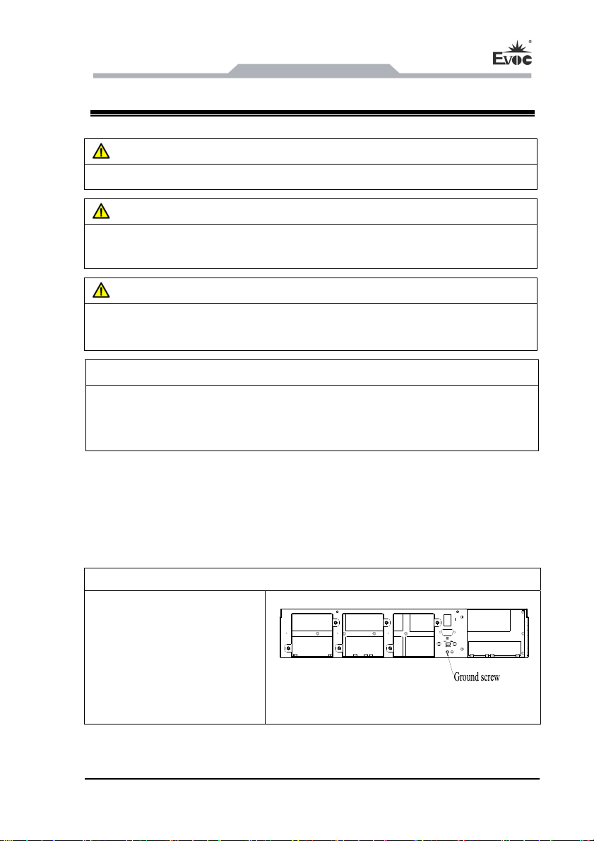
3.2 Product Grounding
Low impedance ground connection is more helpful to release the interference
produced by the external cables, the signal cables or the cables connecting the IO
module to the grounding system.
Ground Terminals
Connect the grounding wire to
the ground screw of the chassis.
The minimum cross section
area of the cable shall be no less
2
than 5mm
.
NPC-8210 - 7 -
the grounding locations of NPC-8210
Page 13

3.3 Connecting the Device to Power
Steps to connect the device to power:
Connect the power cable to the
single power supply AC power
connector, please confirm the
input voltage is accord with the
characteristic of the product
supply before insertion.
Steps to connect the device to power:
Connect the power cable to the
redundant power supply AC
power connector, please confirm
the input voltage is accord with
the characteristic of the product
supply before insertion.
Device Connection
NPC-8210 single power supply
NPC-8210 redundant power supply
- 8 - NPC-8210
Page 14
Operating
Instructions
4. Operating Instructions
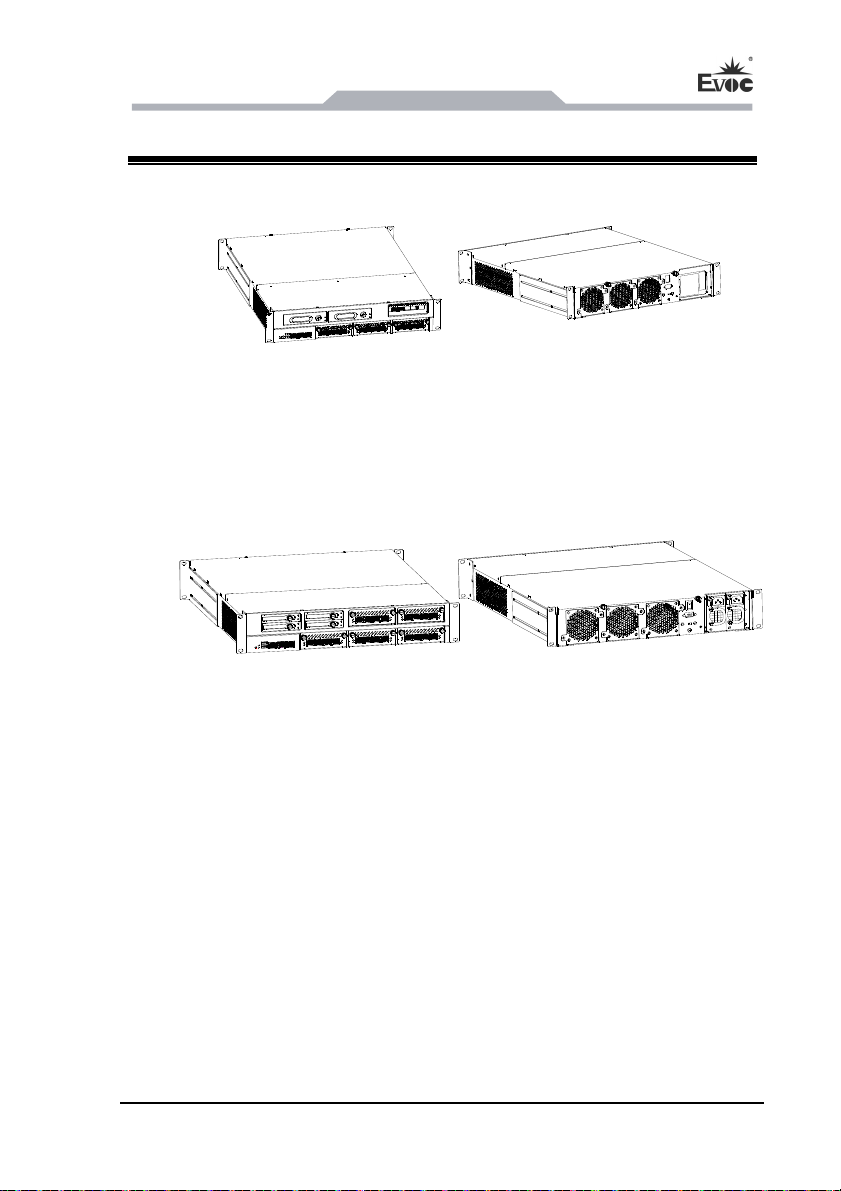
4.1 Outer Appearance
NPC-8210 (used with NET-2814VD2N(B)-01 motherboard)
Different configuration, slight difference in outer appearance. In this picture, the
front panel supports expansion to ENC card
NPC-8210 (used with NET-2814VD2N(B)-02 motherboard)
Different configuration, slight difference in outer appearance. In this picture, the
front panel supports four 2.5-inch HDD trays as full configuration.
NPC-8210 - 9 -
Page 15
Operating Instructions
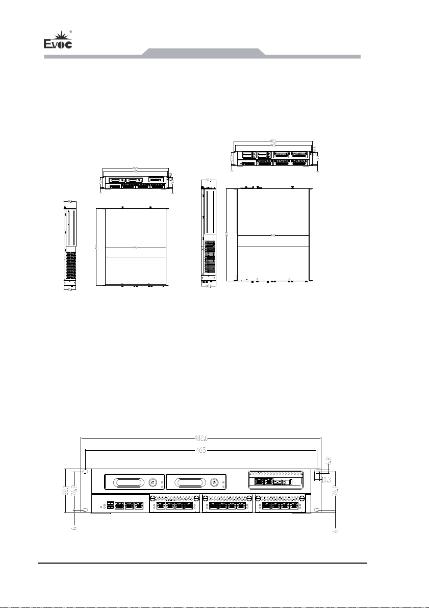
4.2 Product External Dimensions and Installation Dimensions
4.2.1 Product Dimensions Drawing
Product outer dimensions drawing. The front panel may vary slightly based on the
mated motherboard and configuration.
used with NET-2814VD2N(B)-01 used with NET-2814VD2N(B)-02
motherboard motherboard
Unit: mm
4.2.2 Installation Dimensions Drawing
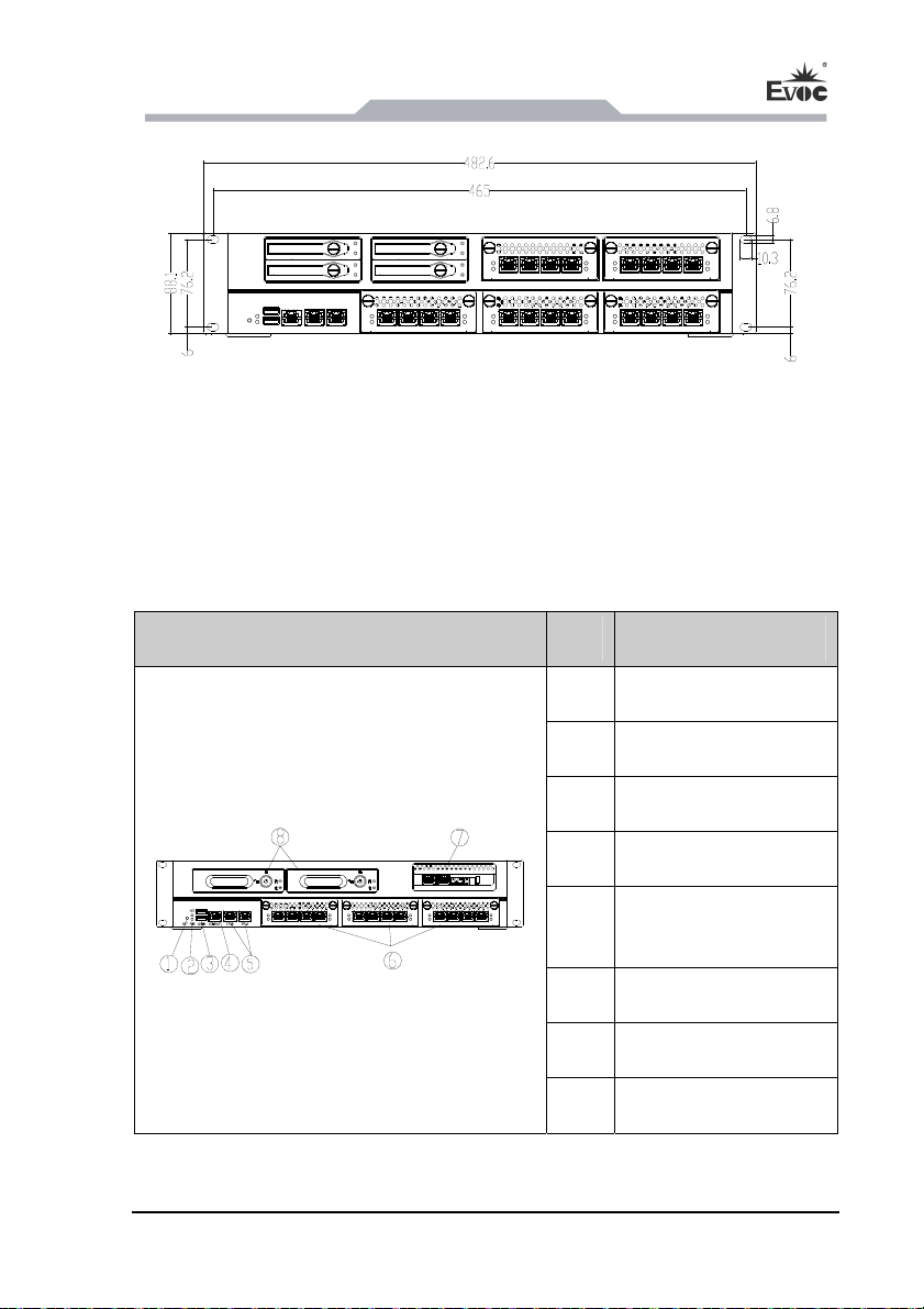
NPC-8210 product installation dimensions drawing. The front panel may vary slightly
based on the mated motherboard and configuration.
used with NET-2814VD2N(B)-01 motherboard
- 10 - NPC-8210
Page 16
Operating
Instructions
used with NET-2814VD2N(B)-02 motherboard
Unit: mm
4.3 External Structure
NPC-8210 (used with NET-2814VD2N(B)-01 motherboard)
Front view of the device
Item Description
① Reset button
② LED
③ USB
④ CONSOLE port
ETH-A/IPMI port or
⑤
ETH-A/ETH-B
⑥ Drawable ENM module
⑦ ENC module(optional)
⑧ 3.5-inch drawable HDD
NPC-8210 - 11 -
Page 17
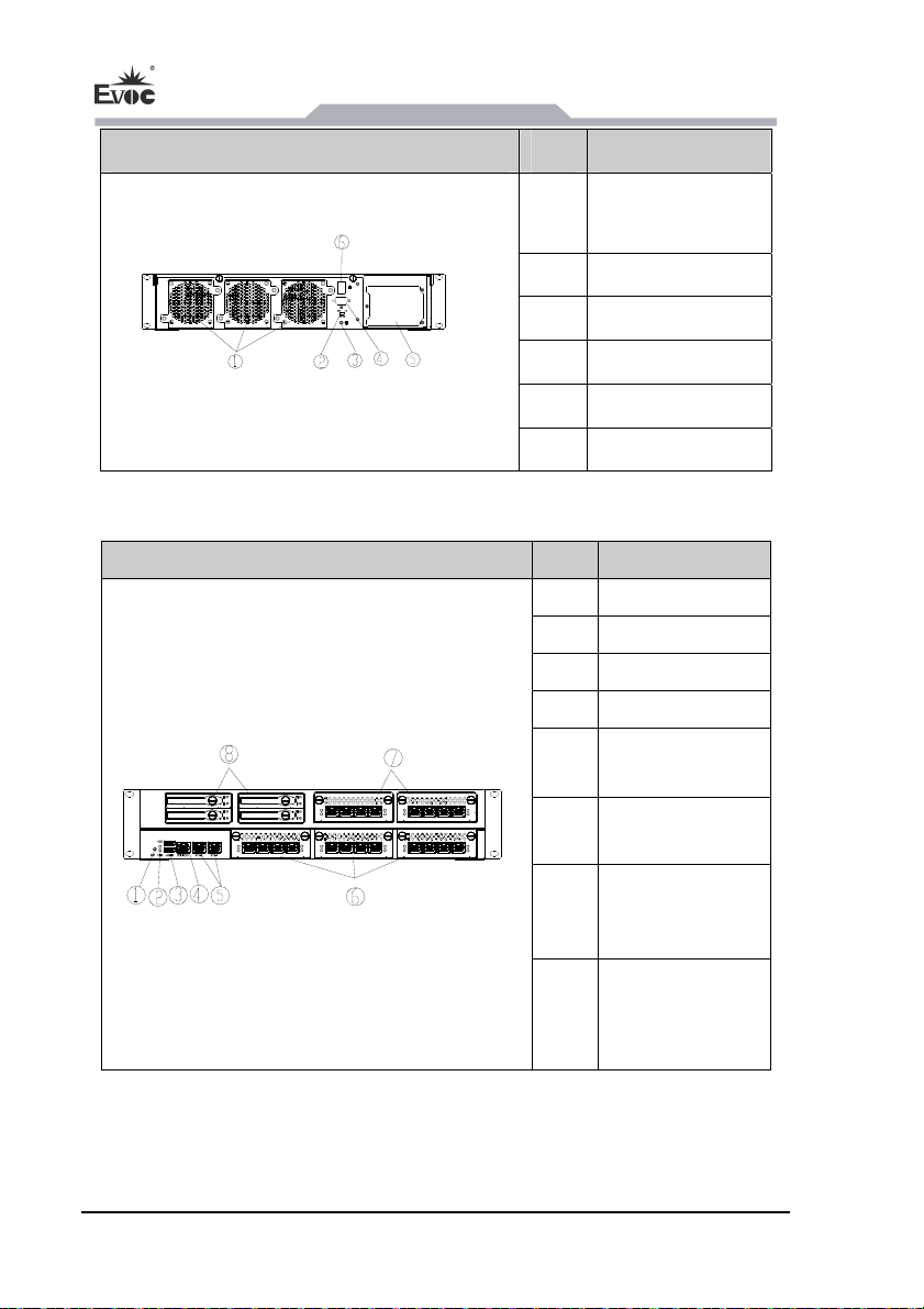
Rear view of the device Item Description
①
② BYPASS switch
③ Ground screw
④ VGA
⑤ Power
⑥ Power switch
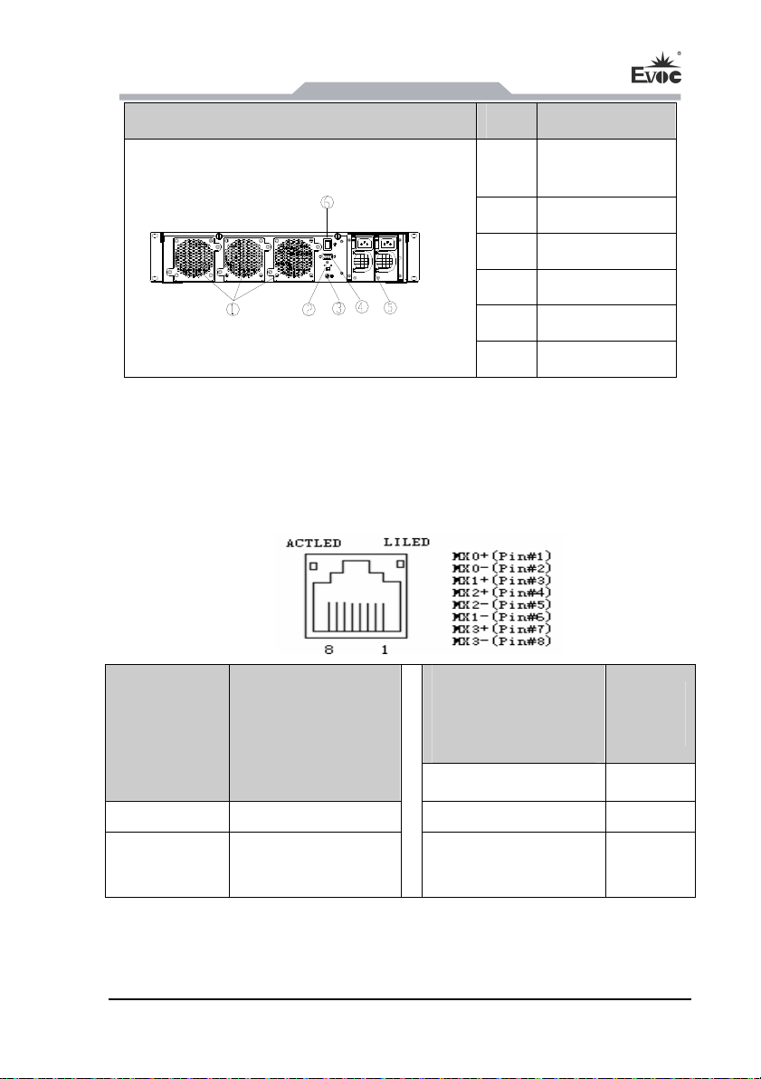
NPC-8210(used with NET-2814VD2N(B)-02 motherboard)
Front view of the device Item Description
① Reset button
② LED
③ USB
④
⑤
Operating Instructions
Drawable fan
module
CONSOLE port
ETH-A/IPMI port
or ETH-A/ETH-B
- 12 - NPC-8210
Drawable ENM
⑥
module
Drawable ENM
⑦
module
2.5-inch drawable
⑧
HDD(Optional
quantity)
Page 18
Operating
Instructions
Rear view of the device Item Description
Drawable fan
①
module
② BYPASS switch
③ Ground screw
④ VGA
⑤ Power
⑥ Power switch
4.4 Port Definition
4.4.1 Network Port
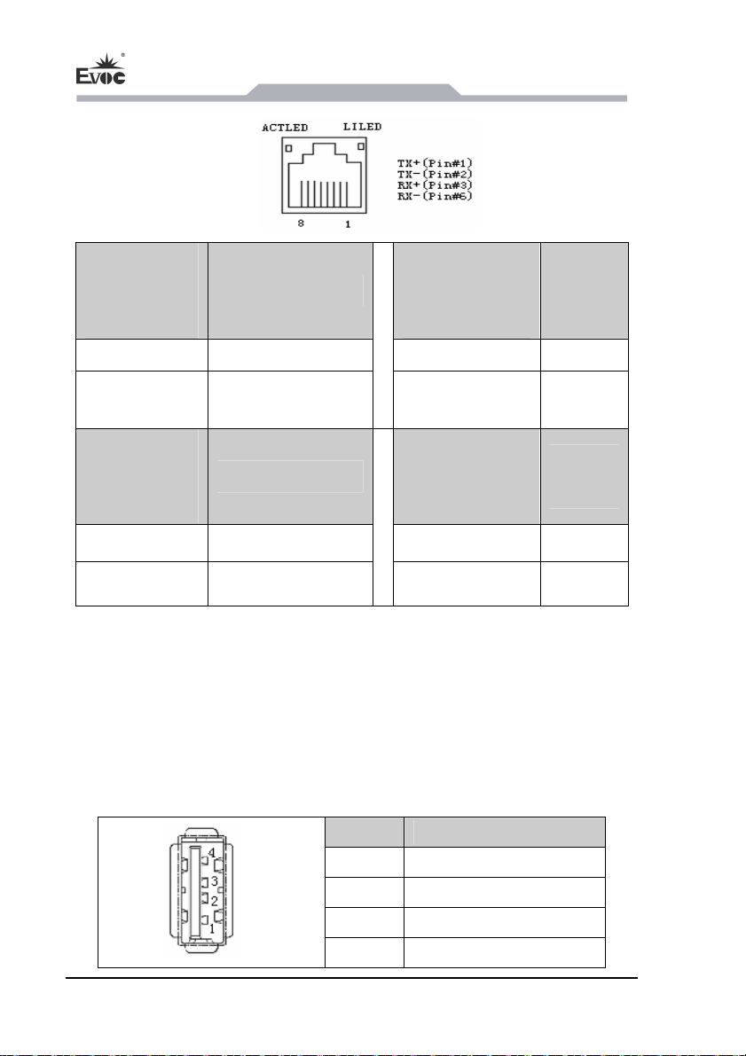
1. The front panel provides one 10/100/1000Mbps RJ45 network port LAN1,
supporting Wake-On-LAN. Its pin definition is as follows:
ACTLED
(single color:
green)
Flash
LILED
(dual-color: yellow and
Network activity
Data being transmitted Yellow
green)
Green
Network
speed
1000Mbps
100Mbps
Off
2. The front panel provides one 10/100Mbps RJ45 IPMI management port LAN2. Its
pin definition is as follows:
No data being
transmitted
NPC-8210 - 13 -
Off 10Mbps
Page 19
Operating Instructions
ACTLED
(single color:
green)
Flash
Off
ACTLED
(single color:
green)
Flash
Off
3. The front panel provides two 10/100/1000Mbps RJ45 network ports. LAN1
supports Wake-On-LAN. Their pin definitions are the same with LAN1 on the front
panel.
Network activity
Data being transmitted
No data being
transmitted
Network activity
Data being transmitted
No data being
transmitted
LILED
Network
(dual-color:
speed
yellow and green)
Yellow Linked
Off Not linked
LILED
Network
(dual-color:
speed
yellow and green)
Yellow 100Mbps
Off 10Mbps
4.4.2 USB Port
The front panel provides two front-accessible USB ports. Their pin definitions are as
follows:
- 14 - NPC-8210
Pin Signal Name
1
2
3
J2
4
+5V_USB
USB_DATA-
USB_DATA+
GND
Page 20
Operating
Instructions
4.4.3 COM Port
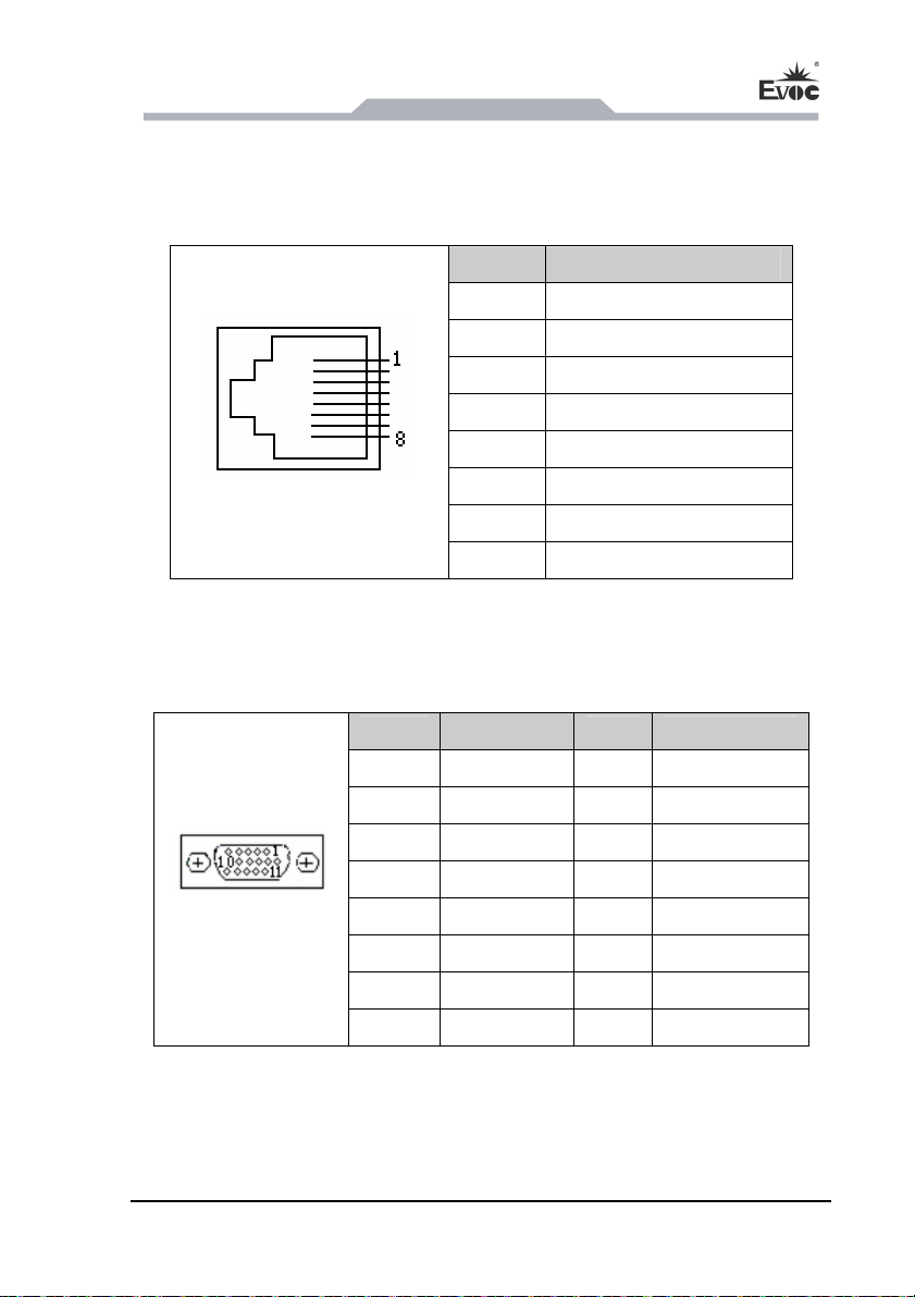
The front panel provides two COM ports. COM1 is RJ45 port, and supports serial
port redirection. Its pin definition is as follows:
COM1
Pin Signal Name
1
2
3
4
5
6
7
8
RTS #
DTR#
TXD
GND
GND
RXD
DSR#
CTS#
4.4.4 Display Port
The rear panel provides one VGA port. Its pin definition is as follows:
Pin
1 Red 2 Green
3 Blue 4 NC
5 GND 6 GND
Signal
Pin Signal Name
7 GND 8 GND
VGA
9 NC 10 GND
11 NC 12 DDCDATA
13 HSYNC 14 VSYNC
15 DDCCLK
NPC-8210 - 15 -
Page 21
4.5 Operation Control
Warning!
On/Off switch will not disconnect the device rom power!
Attention!
When device executes hardware reset, data might be lost.
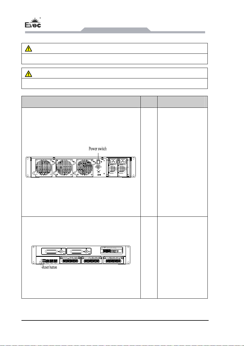
Control button Item Description
Operating Instructions
On/Off button used
to turn on/off the
device. Note: To
shut off the device,
you only need to
carry out the
①
power-off program
in the system, and
you do not have to
press this button,
which is used for
power-on only.
Reset button.
Use a pointed object
or a clip to operate
the reset button.
This button will
②
trigger hardware
reset. The device
executes reboot
(cold reset)
- 16 - NPC-8210
Page 22
Operating
g
d
d
d
Instructions
4.6 Indicators
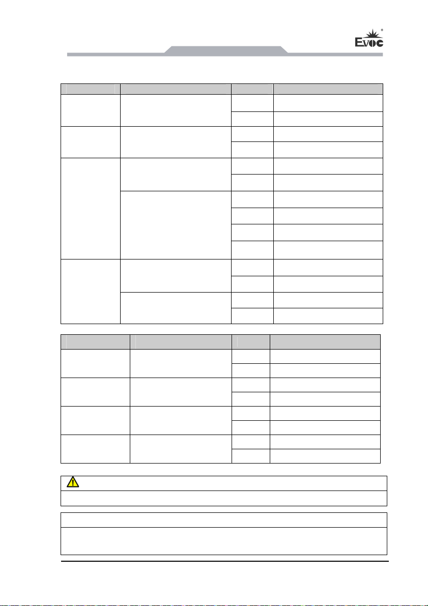
NPC-8210-01:
Indicator Meanin
PWR Device status
HDD Access to the hard drive
ACTLED status
ETH-A
LILED status
LED Description
Off Disconnected from power
Gree Device is running
Off No access
Yellow Being accessed
Off No data communication
Green Data communication
Off Not linked or10Mbps
Green 1000bps
Yellow 100Mbps
Green Data communication
ACTLED status
IPMI
LILED status
NPC-8210-02:`
Indicator Meaning
PWR Device status
HDD Access to the hard drive
ETH-A ETHERNET status
ETH-B ETHERNET status
Off No data communication
Green Data communication
Off Not linked
Yellow Being linked
LED Description
Off
Green Device is running
Off No access
Yellow
Off Not linke
Green Data communication
Off Not linke
Green Data communication
Disconnected from power
Being accesse
Danger!
Disconnect the power source and data cable during a lightning storm.
Attention!
The device is completely isolated from the power supply only by disconnecting the
power connector.
NPC-8210 - 17 -
Page 23

Operating Instructions
4.7 IPMI instructions
1. Functions realized by IPMI
(1)Power-on/off, reboot or other remote control by network;
(2)Real-time monitoring of hardware information of the host PC. When
abnormality occurs, the buzzer will give alarm and send information by network.
2. IPMI default configuration
IP address: 192.168.102.254
Network gate: 192.168.102.3
Subnet mask code: 255.255.255.0
3. Telnet command of IPMI
After the network is connected to IPMI, prompt information will be popped out
automatically. Input “?” or “help” command to display more information.
Command Operation method Example result
get_sys_temperature
get_sys2_temperature
get_cpu1_temperature
get_cpu2_temperature
get_sysfan1_speed
Get system temperature, and input on CLI interface
cli>get_sys_temperature
Get system temperature 2, and input on CLI interface
cli>get_sys2_temperature
Get CPU1 temperature, and input on CLI interface
cli>get_cpu1_temperature
Get CPU2 temperature, and input on CLI interface
cli>get_cpu2_temperature
Get system fan 1, and input on CLI interface
cli > get_sysfan1_speed
sys_temperature=41℃
sys2_temperature=43℃
cpu1_temperature=56℃
cpu2_temperature=54℃
sysfan1_speed=4515rpm
- 18 - NPC-8210
Page 24

Operating
get_sysfan2_speed
Instructions
Get system fan 2, and input on CLI interface
cli>get_sysfan2_speed
sysfan2_speed=4383rp
get_sysfan3_speed
get_cpufan1_speed
get_cpufan2_speed
get_vcore1_value
get_vcore2_value
get_v_3_3_value
get_v_5_value
get_v_12_value
get_v_bat_value
Get system fan 3, and input on CLI interface
cli>get_sysfan3_speed
Get CPU1 fan speed, and input on CLI interface
get_cpufan1_speed
Get CPU2 fan speed, and input on CLI interface
cli> get_cpufan2_speed
Get vcore1 voltage value, and input on CLI interface
cli>get_vcore1_value
Get vcore2 voltage value, and input on CLI interface
cli>get_vcore2_value
Get actual value of 3.3 voltage, and input on CLI
interface
cli > get_v_3_3_value
Get 5V voltage value, and input on CLI interface
cli> get_v_5_value
Get 12V voltage value, and input on CLI interface
cli> get_v_12_value
Get vbat voltage value, and input on CLI interface
cli>get_v_bat_value
sysfan3_speed=4515rpm
cpufan1_speed=2184rpm
sysfan2_speed=0rpm
vcore1_value=0.968V
vcore2_value=0.704V
v_3_3_value=3.344V
v_5_value=5.041V
v_12_value=12.144V
v_bat_value=3.152V
hwmonitor
Detect hardware information, and input on CLI
interface
cli > hwmonitor
NPC-8210 - 19 -
sys_temperature =53℃
cpu1_temperature=57℃
cpu2_temperature=0℃
sysfan1_speed=0rpm
sysfan2_speed=0rpm
sysfan3_speed=0rpm
cpufan1_speed=2033rpm
cpufan2_speed=0rpm
Page 25

set_sys_threshold
set_cpu1_threshold
set_cpu2_threshold
get_sys_threshold
get_cpu1_threshold
get_cpu2_threshold
Set temperature alarm threshold. On CLI interface,
input set_XXX_threshold, threshold1, threshold2
and threshold3. When the actual temperature is
above threshold1, the buzzer gives alarm for once;
when the actual temperature is above threshold2, the
buzzer gives alarm for twice; when the actual
temperature is above threshold3, the buzzer gives
alarm for three times;
cli>set_sys_threshold 60 70 80
cli>set_cpu1_threshold 60 70 80
cli>set_cpu2_threshold 60 70 80
Set the threshold values according to the actual
needs. It is not appropriate to set the values too high
or too low. The former may make the alarm
ineffective, and the latter may lead to frequent alarm.
Usually default settings are used.
Check current temperature alarm threshold values.
For example, input on CLI interface
cli > get_sys_threshold
Operating Instructions
vcore1_value=0.968V
vcore2_value=0.760V
v_5_value=4.888V
v_3_3_value=3.120V
v_12_value=11.880V
v_bat_value=3.200V
sys_threshold:80 80 80
reset_system
start_system
Reset system, and input on CLI interface
cli>reset_system
Start system, and input on CLI interface
cli>start_system
- 20 - NPC-8210
Page 26

Operating
close_system
set_ip
get_log
Instructions
Close system, and input on CLI interface
cli>close_system
Input close_system to check whether “close system”
is finished. If the system is not shut down within 2
minutes, automatic power-off will be executed, and
no response will be given to other command in the 2
minutes of monitoring.
Set IP; input set_ip, IP address, network gate address
and subnet mask code
cli>set_ip
192.168.102.254
192.168.105.3 255.255.255.0
After inputting ip, the network is disconnected. Use
new ip address for login.
Check abnormal temperature log. Input get_log to
check abnormal information, which includes time,
faulty parts and temperature.
get_mac
get_time
set_time
disconnect
reset_ipmi
Check IPMI network card MAC address, and input
get_mac on CLI interface
Check IPMI system time, and input get_time on CLI
interface
Set IPMI system time, and input on CLI interface
cli > set_time
Disconnect telnet link, and input on CLI interface
cli >disconnect
Reset IPMI, and input on CLI interface
cli >reset_ipmi
NPC-8210 - 21 -
002246xxxxxxx
2013.01.01 12:00
2013-1-1 13:00
Page 27

Operating Instructions
4.8 Using System Setup Program and UEFI Boot Manager
During bootup, the following keys can be used to realize system functions.
Table 1 Function Key During Bootup
Function key Description
Enter into system setup program.
<DEL>
<F2>
<F7>
<Ctrl>+<S>
System setup boot program is a BIOS program, an option which enables you to
manage system hardware and designated BIOS class. By system setup program, you
can:
Modify NVRAM settings after adding or deleting hardware.
Check system hardware configuraiton
Enable or disable integrated devices.
During serial port redirection, use “<ESC>-” to replace <DEL> to
enter into system setup program.
Enter into system setup program.
During serial port redirection, use “<ESC>2” to replace <DEL> to
enter into system setup program.
Enter into BIOS load manager, and select load device.
During serial port redirection, use “<ESC>7” to replace <DEL> to
enter into system setup program.
Configure NIC setting for PXE boot (if it has been enabled, please
refer to “Using System Setup Program”), which is only applicable to
NPC-8210 complete PC.
Set up performance and power management threshold value.
Manage system security.
Select System Boot Mode
By system setup program, you can designate boot mode to facilitate installation of
operating system.
- 22 - NPC-8210
Page 28

Operating
UEFI BIOS specificaitons.
You can set up under the menu of “Boot -> CSM parameters -> Boot option filter” in
the system setup program, as shown in Table 2. Once the boot mode is designated, the
system will adopt the designated boot mode for bootup. You install the operating
system by this mode, so you must set the system boot to the same boot mode (Legacy
or UEFI” to access the installed operating system. If you try to boot the operating
system from other mode, it will cause system bootup failure.
Note: The operating system must be compatible with UEFI (e.g., Microsoft Windows
Server 2008 x64 version), so that installation can be carried out by UEFI boot mode.
DOS and 32-bit operating system do not support UEFI, so they can be installed only
by Legacy boot mode.
Instructions
Legacy boot mode (default) is standard BIOS class boot port.
UEFI boot mode is an enhanced 64-bit boot port, which is compliant with
Table 2 Select System Boot Mode
Aptio Setup Utility – Copyright (C) 2012 American Megatrends, Inc.
Boot
→←:Select Screen
Boot option filter [legacy Only]
Launch PXE OpROM policy [Do not launch]
Version 2.15.1222226. Copyright (C) 2012,American Megatrends, Inc.
NPC-8210 - 23 -
↑↓:Select Item
Enter:Select
+/-:Change Opt
F1:General Help
F2:Previous Values
F3:Optimized Defaults
F4:Save
ESC:Exit
Page 29
Operating Instructions
Enter into System Setup Program(BIOS Setup)
1. Boot up or reboot the system
2. When the system displays the following information, press <DEL> or
<F2>.
Version 2.15.1234. Copyright (C) 2012 American Megatrends,Inc.
Press <DEL> or <F2> to enter setup. Press <F7> for popup menu.
Use system setup program navigation keys.
Table 3 System Setup Program Navigation Keys
Key Description
→← Screen switch for the whole screen
↑↓ Switch among fields
Enter Select an option
+/- Browse setup in fields by rolling. You can key in appropriate value
among many fields.
F1 Display help information of system setup program
F2 Restore to system settings before the change.
F3 Load BIOS default optimized settings
F4 Save and exit
ESC Return to last menu or exit the system setup program
Notes: For most options, the changes you made will be recorded, but they will take
effect only after the system is rebooted.
The following sections list the system setup program options you may make changes.
As for the detailed explanations about the functions of option, please refer to the
“BIOS Setup” chapter in the motherboard user manual CD.
- 24 - NPC-8210
Page 30
Operating
Main Screen
Note: The options of system setup program may vary with system configurations.
Instructions
Table 4 Main Screen
Aptio Setup Utility – Copyright (C) 2012 American Megatrends, Inc. opyright (C)
Main Advanced Chipset Boot Security Save & Exit
Motherboard Information
Product Name NET-2814Seriess
BIOS Name C916400F
BIOS Version B01
Build Date 09/10/2013 20:55:38
Memory Information
Total Memory 2048 MB (DDR3)
System Date [Thu 12/26/2013]
System Time [09:41:55]
Access Level Administrator
Version 2.15.1236. Copyright (C) 2012,American Megatrends, Inc.
Table 5 Main Screen Setup
Set the Date. Use‘Tab’ to
switch between Date
elements.
→←:Select Screen
↑↓:Select Item
Enter:Select
+/-:Change Opt
F1:General Help
F2:Previous Values
F3:Optimized Defaults
F4:Save ESC:Exit
Option Description
System Date Set up the date within the system.
System Time Set up the time within the system.
NPC-8210 - 25 -
Page 31
Operating Instructions
CPU Setup Screen (Advanced -> CPU Configuration)
Table 6 CPU Screen Setup
Option Description
Hyper-threading Enabled/Disabled CPU Hyper-threading function
Active Processor Cores
CPU Power Management
Configuration
Table 7 CPU Power Supply and Performance Management Interface
Option Description
Disable:Disable CPU power management funciton
Power Technology
EIST Enabled/Disabled Intel CPU SpeedStep function
Turbo Mode Enabled/Disabled IntelCPU Turbo Mode function
Energy
Performance
SATA Setup Interface (Advanced -> SATA Configuration)
Option Description
SATA Mode The options include IDE mode and AHCI mode.
Port 1 ~ 6 Hot
Plug
Custom:User self-defined
Energy Efficient:Minimum power
Performance:Maximum performance
Balanced Performance:Dynamic adjustment of CPU
performance
Balanced Energy: Dynamic adjustment of CPU power
consumption
Energy Efficient:Minimum power
Enable or disable HDD hotswap function under AHCI mode.
Note: It can be used only when it is supported by driver under
operating system.
Set up the number of CPU cores used by the
system, only effective for multi-core CPU.
Set up CPU power supply and performance
management option
Table 8 SATA Setup Interface
- 26 - NPC-8210
Page 32
Operating
SAS Setup Interface (Advanced -> SAS Configuration)
Boot Setup Interface
Instructions
Table 9 SAS Setup Interface
Option Description
Onboard SAS Oprom/Driver Enable or disable onboard SAS function.
Table 10 Boot Setup Interface
Option Description
Quiet Boot Enable or disable bootup LOGO function
CSM parameters Set up boot mode menu
Table 11 Boot Mode Setup Interface
Option Description
Set up boot mode
Boot Option filter
Legacy only: Boot 32-bit system, DOS or 64-bit
Legacy system
UEFI only: Boot 64-bit UEFI system
Launch PXE OpROM policy PXE boot mode selection
Automatic Power-up Mode and PXE Boot Enabled Interface
Table 12 Automatic Power-up Mode and PXE Boot Enabled Interface
Option Description
ethA PXE Boot Enable or disable PXE boot funciton
Set up the system status upon reboot after the PC is
disconnected from AC power.
Restore AC Power Loss
PowerOff: The system is powered off.
PowerOn: The system is powered on automatically.
Last State: It returns to the status before power loss.
NPC-8210 - 27 -
Page 33
Operating Instructions
IPMI Setup Interface (Advanced -> IPMI Configuration, only applicable to
EIS-2203 complete PC)
Table 12 IPMI Setup Interface
Option Description
Enable or disable IPMI configruation function, including
reading or setting up IP adddress, subnet mask, network
IPMI Configuration
gateway of IPMI network port, reading MAC address of
IPMI and realizing time synchronization between host
PC and IPMI system.
IPMI System Time
Configuration
System Security Protection Interface
Option Description
Administrator Password Set up system administrator password
User Password Set up common user password
Exit the Interafce
Press <ESC> to exit the system setup program, to display Exit interface.
Option Description
Save Changes and Reset Save changes and exit
Discard Changes and Exit Discard changes and exit
Enable or disable time synchronization function between
hostPC and IPMI system.
Tabel 13 System Security Setup Interface
Table 14 Exit the Interface
- 28 - NPC-8210
Page 34
Assem
bly and Maintenance
5. Assembly and Maintenance
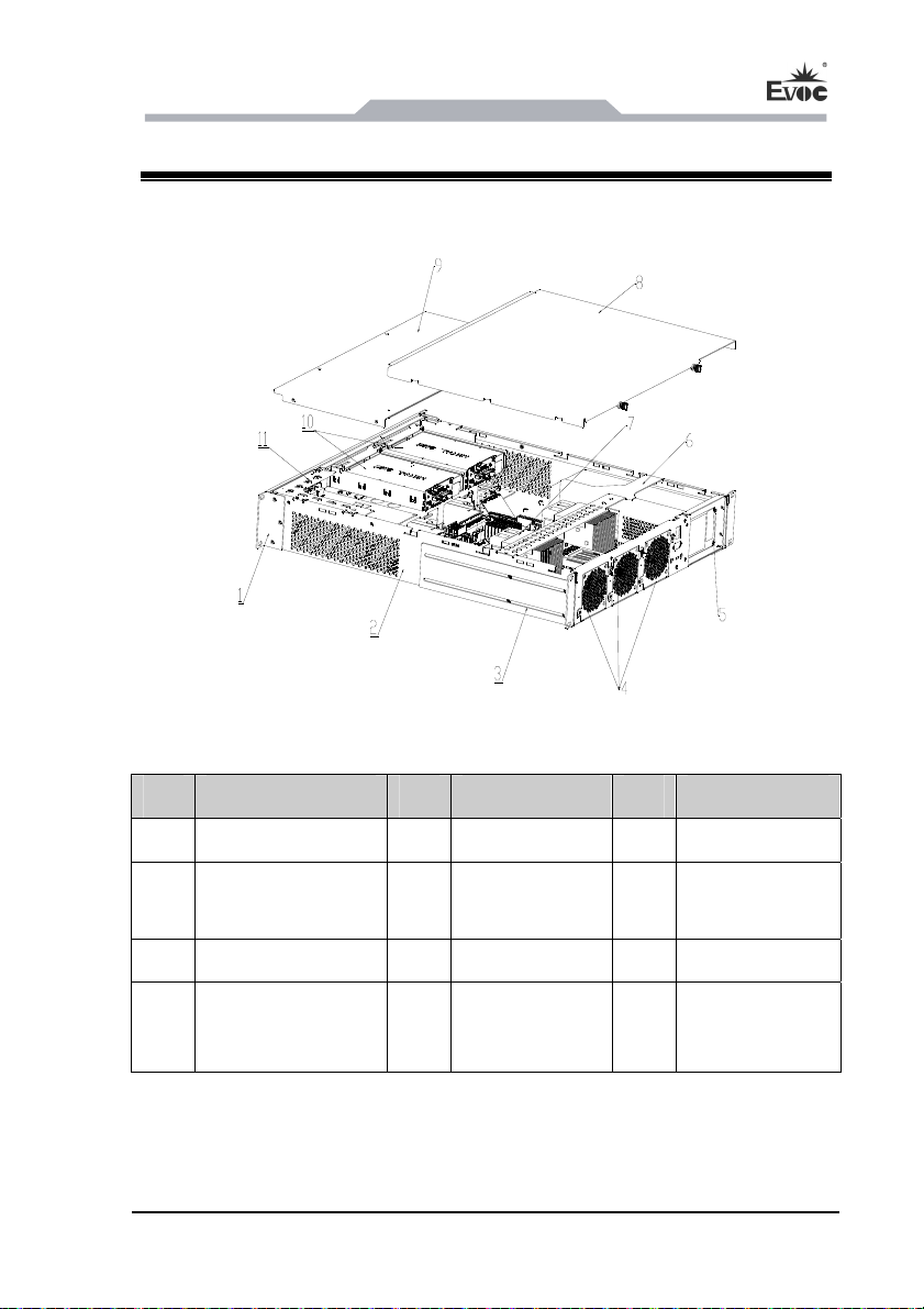
5.1 Overall Assembly Drawing
Item Description Item Description Item Description
1 Mounting ear 2 Chassis 3 Rear mount ear
4
7 Motherboard 8 Chassis cover 9 Front cover
10
Drawable fan
module
3.5-inch drawable
HDD
NPC-8210 is used with NET-2814VD2N(B)-01 motherboard
5 Power supply 6 Wind shield
Expansion
11
module(optional)
NPC-8210 - 29 -
Page 35
Assembly and Maintenance
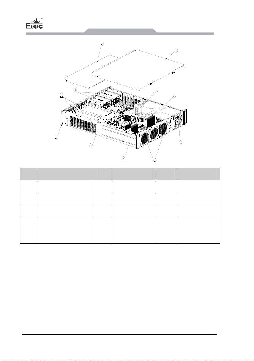
Item Description Item Description Item Description
1 Mounting ear 2 Chassis body 3 Rear mounting
4 Drawable fan module 5 Power supply 6 Wind shield
7 Motherboard 8 Chassis cover 9 Front cover
10
2.5-inch drawable
HDD(Optional quantity)
NPC-8210 is used with NET-2814VD2N(B)-02 motherboard.
11
Expansion
module
- 30 - NPC-8210
Page 36
Assem
bly and Maintenance
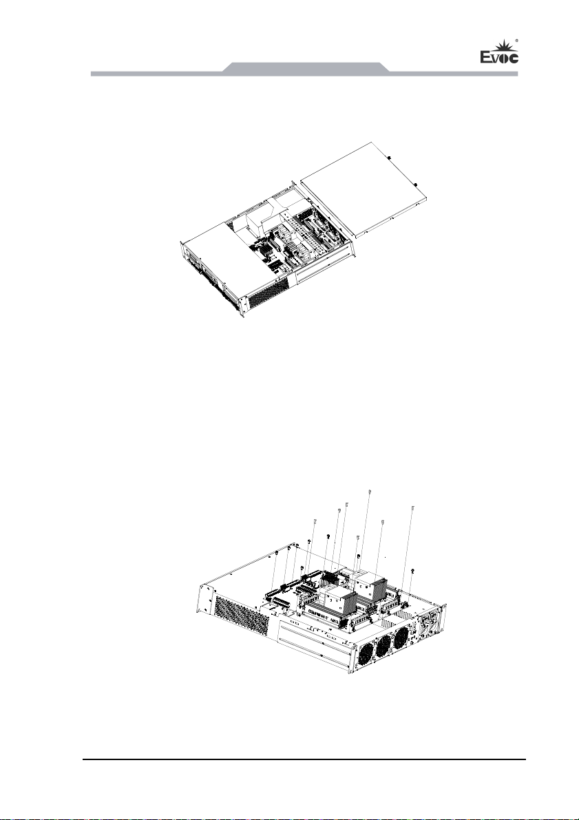
5.2 Opening the Cover
Loosen the two captive screws on the chassis cover, then pull the cover backward to
open the chassis cover.
5.3 Installation and Removal of Motherboard
5.3.1 Installing the Motherboard
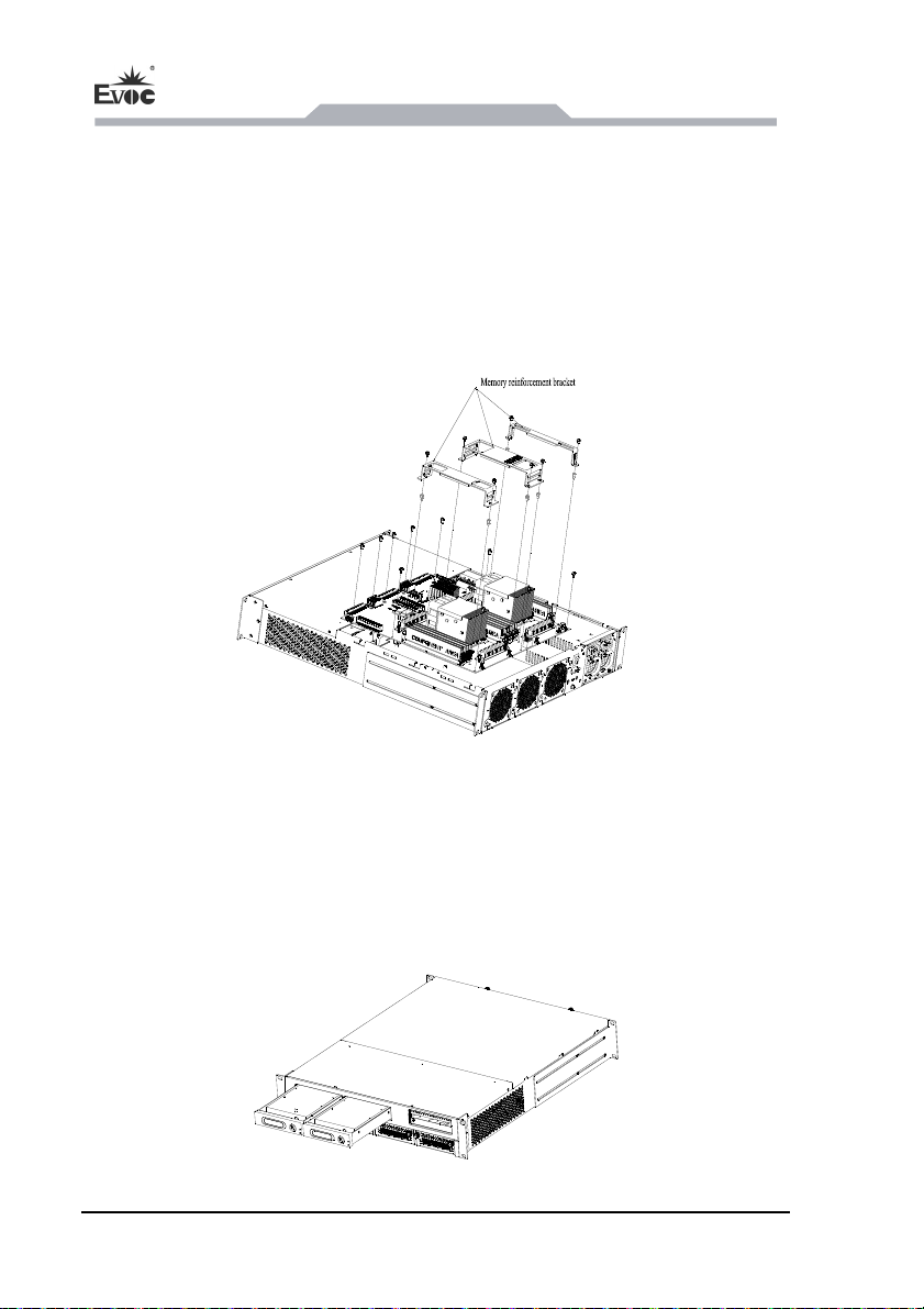
1. Place the motherboard inside the chassis, use ten M3 pan head combo screws to
fasten it.
2. Use seven M3*6 hex copper studs to fasten the motherboard memory module.
NPC-8210 - 31 -
Page 37
Assembly and Maintenance
5.3.2 Removing the Motherboard
1. Open the chassis cover, and remove the riveted assembly of wind shield;
2. Remove the trapezoid converter board linked with IO board;
3. Remove the memory reinforcement brackets;
4. Loosen the ten M3 screws and seven hex studs, then you can remove the
motherboard.
5.4 Installation and Removal of HDD
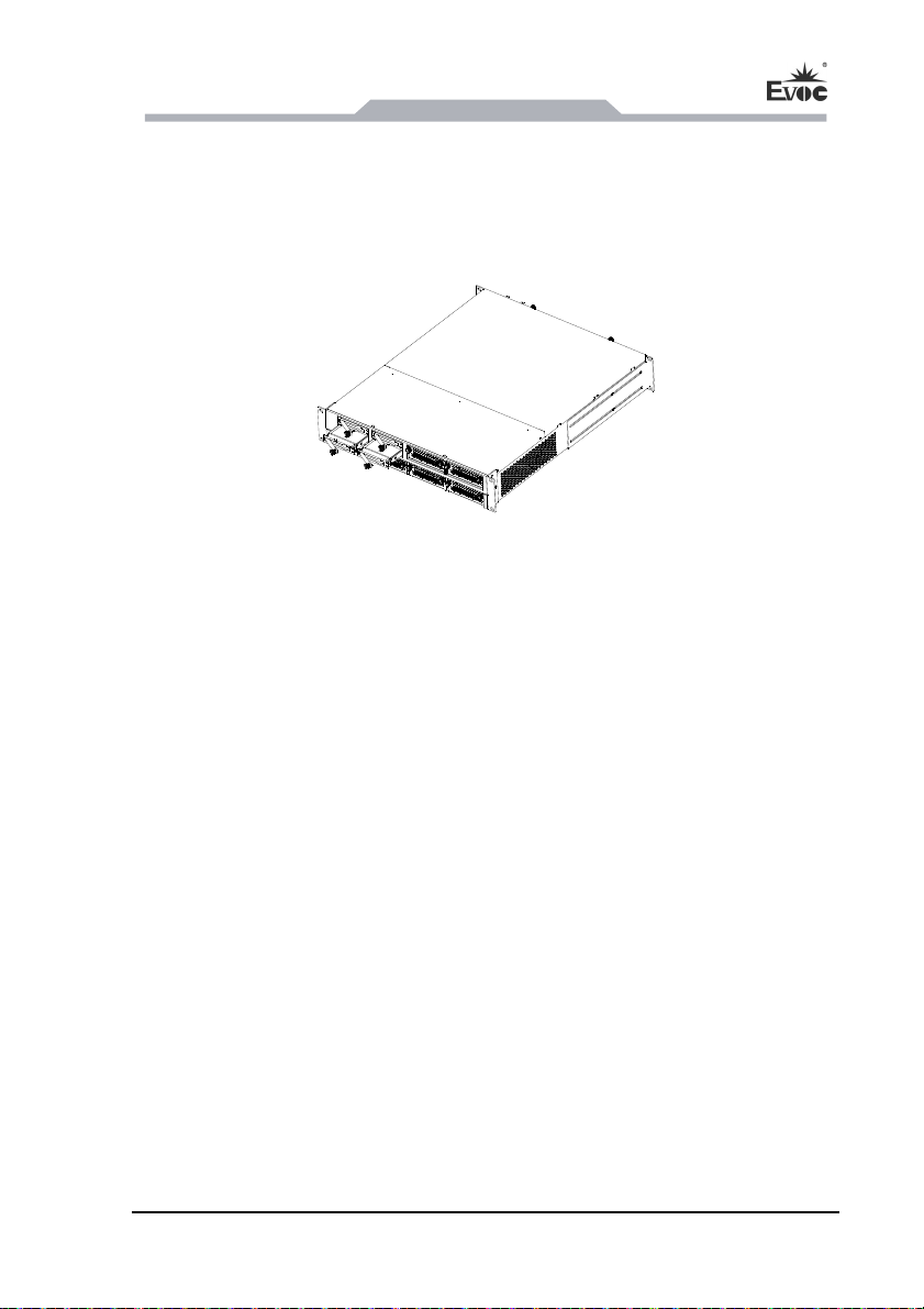
NPC-8210 is used with NET-2814VD2N(B)-01 motherboard, and has two 3.5-inch
drawable HDD. Use the key in the accessory kit to open the lock on the HDD case,
grasp the handle on the case and pull it outward to take out the 3.5-inch HDD from
the chassis, so as to replace or install HDD.
NPC-8210 is used with NET-2814VD2N(B)-01 motherboard
- 32 - NPC-8210
Page 38
Assem
bly and Maintenance
NPC-8210 is used with NET-2814VD2N(B)-02 motherboard, and supports four
2.
5-inch drawable HDDs as full configuration. Loosen the captive screws on the HDD
handle, grasp the handle and pull it outward to take out the four 2.5-inch HDD from
the chassis, so as to replace or install HDD.
NPC-8210 is used with NET-2814VD2N(B)-02 motherboard
5.5 Installation and Removal of Power Supply
5.5.1 Installing the Power Supply
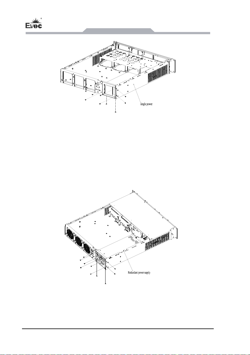
When NPC-8210 is equipped with single power supply, use six M3 sunkhead screws
to fasten the power bracket onto the chassis, place the power supply inside the chassis,
use three sunkhead #6-32*1/4 screws to fasten the power supply onto the bracket,
then use two sunkhead #6-32*1/4 screws to fasten the tail end of the power supply
from bottom of the chassis (The power supply has internal bracket) If tthe power
supply has no internal bracket, use two sunk head #6-32*1/4 screws to fasten the
power supply to the internal bracket, then use two M3 sunk head screws to fasten the
tail part of power supply from bottom of the chassis.
NPC-8210 - 33 -
Page 39
Assembly and Maintenance
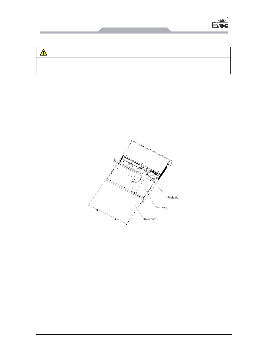
NPC-8210 is equipped with redundant power supply, use six M3 sunkhead screws to
fasten the power bracket onto the chassis body, place the power supply inside the
chassis, use four sunkhead #6-32*1/4 screws to fasten the power supply onto the
bracket, then use one M3 combo screw to fasten the tail end of the power supply onto
the chassis from inside of the chassis.
- 34 - NPC-8210
Page 40
Assem
bly and Maintenance
5.5.2 Removing the Power Supply
Danger!
Before removing the power module, if power is connected, it must be turned off and
cable unplugged.
The steps to remove power supplies of NPC-8210 equipped with single and redundant
power supply
the screws fixing the power bracket, power supply and tail end of power supply, and
pull out the power cable terminal, then you can take out the power supply from the
chassis.
are the same: first open the chassis cover, remove the fan shield, loosen
5.6 Installation and Removal of Fan
5.6.1 Installing the Fan
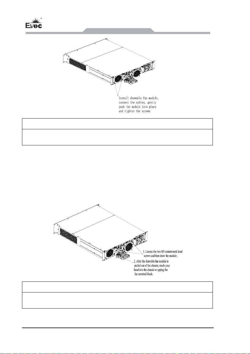
NPC-8210 adopt externally rawable fans, and the cables can be inserted or pulled out
outside the chassis. Reach your fingers into the fan hole to insert the fan terminal
outside the chassis, push the fan module into the fan hole, then tighten the two M3
countersunk head screws on the fan panel, as shown in the figure below:
NPC-8210 - 35 -
Page 41
Assembly and Maintenance
Attention!
Because the fans rotate at fast speed, do not touch the fans before they stop working.
5.6.2 Removing the Fan
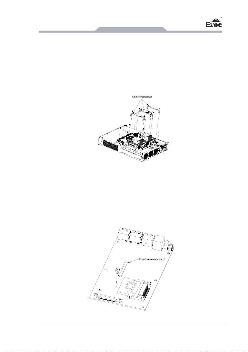
Loosen the two M3 screws on the fan panel, then the fan module can be separated
from the chassis. Lay the fan on the table, and reach your fingers into the fan hole to
pull out the cable terminal, as shown in the figure below:
Attention!
Because the fans rotate at fast speed, do not touch the fans before they stop working.
- 36 - NPC-8210
Page 42
Assem
bly and Maintenance
5.7 Special Installation Instructions
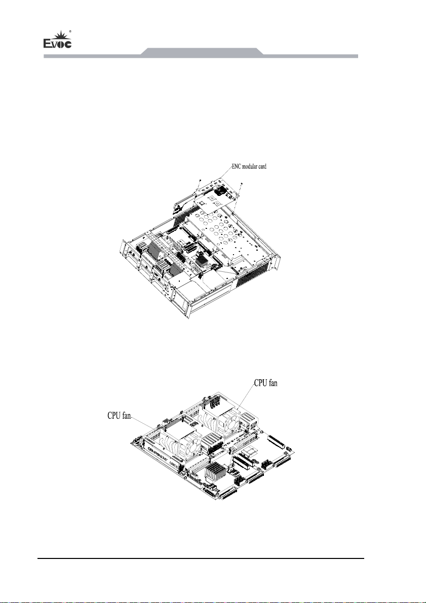
5.7.1 Memory Module Reinforcement
Install step screws with gasket on the memory reinforcement brackets. These
screws will not fall out from the brackets.
Directly align the brackets with hex studs and tighten the screws.
5.7.2 CF Card Reinforcement
Install step screws with gasket on the CF card reinforcement brackets. These
screws will not fall out from the brackets.
Directly align the brackets with hex studs and tighten the screws.
NPC-8210 - 37 -
Page 43
Assembly and Maintenance
5.7.3 Installing ENC Modular Card (optional)
When NPC-8210 is used with NET-2814VD2N(B)-01 motherboard, it can choose
ENC Modular Card. The installation stepsare as follows:align the converter board
gold finger of ENC modular card with PCIE slot of the motherboard, insert the card
downward with force to the bottom of the slot, then use two sunkhead screws to fasten
it.
5.7.4 Installing the CPU Fans
Please pay attention to the polarity when installing the CPU fans.
- 38 - NPC-8210
Page 44

Installing
the Drivers
6. Installing the Drivers
Regarding the installation of the driver program and the detailed information of the
motherboard, please refer to the enclosed CD of the PC.
NPC-8210 - 39 -
Page 45

7. Appendix
7.1 Troubleshooting and Solutions
Common
Malfunctions
No power supply
The device is not
operating
The external
display is black
Incorrect time or
date on device
Improper device operating
environment
The display has not been
turned on
The display is under
“power saving” mode
The luminance control is
set to “Black”.
Power cable or display
cable is not connected
Incorrect BIOS setting
Reasons Troubleshooting and Solution
Appendix
Please check the power supply
and the power cable/connector.
1. Check with the environment
conditions;
2. Please wait for twelve hours
before powering on the device
shipped in cold weather.
Turn on the display
Press any key on the keyboard.
Increase the screen luminance by
luminance control. Please refer to
the instructions of the display for
detailed information.
1. Please check whether the
power cable is correctly
connected with the display, the
system unit or the ground port.
2. Please check whether the
display cable is correctly
connected with the display and
the system unit.
3. Contact Technique Support if
the screen remains black after
implementing the above
measures.
Follow the power-on prompt and
press the key to enter the BIOS
Setup; adjust the time and date in
BIOS Setup.
- 40 - NPC-8210
Page 46

Appendix
BIOS setting is
correct while the
time and date are
incorrect.
Insufficient backup battery
capacity
Replace the battery
USB port is disabled in
BIOS
USB 2.0 device is
connected; however, USB
USB device has no
response
The computer is
not booted or
displays “Boot
device not found”
No system disk
can be found when
powering on
2.0 is disabled.
USB port is not supported
by the operating system.
In booting priority of the
BIOS setting, the device is
not the first priority or the
device is not included in
the booting device.
The HDD power cable or
data cable is not connected
well.
System files on the hard
disk are damaged.
Use other USB ports or enable
that port.
Enable USB 2.0.
1. Enable USB Legacy Support
for the mouse and keyboard
(Legacy USB is supported);
2. For other devices, appropriate
USB drivers are required.
Modify the booting priority of the
device in the Boot menu of BIOS
setting or include that device into
the boot priority.
Check whether the power cable
and the data cable of the hard
disk (the hard disk shall be
installed with operating system
and is bootable) are well
connected.
Enter the system (usually WinPE
system) with a bootable disk;
check whether the system in the
hard disk is damaged. Reinstall
the system if necessary.
NPC-8210 - 41 -
Page 47

Plug and play I/O
card, no IO card is
detected or no IO
card can be used
when used again.
Poor contact of the slot.
Appendix
Poor contact is usually caused by
frequent installation/
uninstallation of the PCI or ISA
card, unstable fixing or improper
dust-proof measures; please
remove and install the card for a
few times or use another slot.
- 42 - NPC-8210
 Loading...