

Page 1

特种计算机
Industrial Computer
产品说明书
User Manual
JEC-1503C
15〞上翻盖便携式计算机
15″ Portable PC with Up Flip
Version:C01
Page 2
Legal Information
Warnings
Please pay attention to the tips within the manual so as to avoid personal injury or
property losses. The tips for personal injury are indicated in warning triangles while
the tips only related to property losses have no warning triangles. The warning tips are
listed as follows with the hazardous scale from severe to slight.
Danger
If handled carelessly, death or severe human injury will occur.
Warning
If handled carelessly, death or severe human injury might occur.
Caution
Warning triangle indicates that slight human injury might occur if handled carelessly.
Note
Unexpected result or status might occur, if not handled according to the tips.
Professional Personnel
The product/system covered by the manual can only be handled by qualified and
professional personnel. During operation, please follow the respective instructive
manuals, especially the safety warnings. The professional personnel have been trained
and possess relevant experiences; therefore, he/she could be aware of the risks of the
product/system and avoid possible damages.
EVOC Product
Please pay attention to the following instructions:
Warning
EVOC product can only be used according to the descriptions within the manual,
including the contents and the relevant technical documents. If the products or
components from other companies are required, please get the recommendation and
grant from EVOC first. Proper transportation, storage, assembly, installation,
debugging, operation and maintenance are prerequisite to ensure product safety and
normal operation; therefore, please ensure permitted environment conditions and pay
attention to the tips within the manual.
Page 3

Copyright Notice
Information offered in this manual is believed to be correct at the time of printing, and
is subject to change without prior notice in order to improve reliability, design and
function and does not represent a commitment on the part of the manufacturer. In no
event will the manufacturer be liable for direct, indirect, special, incidental, or
consequential damages arising out of improper installation and/or use, or inability to
use the product or documentation.
This user manual is protected by copyright. No part of this manual may be reproduced,
stored in any retrieval system, or transmitted, in any form or by any means,
mechanical, electronic, photocopied, recorded or otherwise, without the prior written
permission from the manufacturer.
Trademarks
EVOC is a registered trademark of EVOC Intelligent Technology Co., Ltd. Other
product names mentioned herein are used for identification purposes only and may be
trademark and/or registered trademarks of their respective companies.
Warranty Terms:
The warranty on the product lasts for one year. If the user has additional requirements,
the contract signed between the two sides shall prevail.
Please visit our website:
http://www.evoc.com
for more information,
or send an email to the Technical Support Mailbox [email protected]
(International) or [email protected]
(Domestic) for consultation.
Hotline: 4008809666
Page 4

About this manual
Scope of the Manual
The manual is appropriate for EVOC JEC-1503C.
Convention
The term “the Board” or “the Product” within the manual stands for EVOC
JEC-1503C.
Instructions
Safety instructions
To avoid property losses or individual injury, please pay attention to the safety
instructions within the manual. The warnings within the manual are marked with
warning triangle
, which is dependent upon the scale of the potential hazard.
Page 5

Contents
1. Product Introduction .................................................................................................1
1.1 Overview .......................................................................................................1
1.2 Product Specifications ...................................................................................2
2. Application Scheme ..................................................................................................4
2.1 Transportation................................................................................................4
2.2 Storage...........................................................................................................4
2.3 Opening the Box and Initial Examination......................................................4
3. Device Connection....................................................................................................6
3.1 Notices before Connection ............................................................................6
3.2 Product Grounding ........................................................................................6
3.3 Connecting the Device to Power ...................................................................7
4. Instructions ...............................................................................................................8
4.1 Product Outline..............................................................................................8
4.2 Product Appearance and Installation Dimensions..........................................9
4.3 External Structure........................................................................................10
4.4 Operation Control........................................................................................11
4.5 Status Indicator............................................................................................11
4.6 COM Setting................................................................................................12
5. Assembly and Maintenance ....................................................................................13
5.1 Overall Assembly Drawing..........................................................................13
5.2 Removing the Cover....................................................................................14
5.3 Removal/Installation of Motherboard..........................................................14
5.3.1 Installing the Motherboard...................................................................14
5.3.2 Removing the Motherboard .................................................................16
5.4 Removal/Installation of Driver....................................................................17
5.4.1 Installing the Hard Disk .......................................................................17
5.4.2 Removing the Hard Disk......................................................................17
5.5 Removal/Installation
of Power Supply ........................................................18
5.5.1 Installing the Power Supply .................................................................18
5.5.2 Removing the Power Supply................................................................18
5.6 Assembly and Maintenance of Fan..............................................................19
Page 6

5.6.1 Installing the Fan..................................................................................19
5.6.2 Removing the Fan................................................................................19
5.7 Assembly and Maintenance of Dust-proof Net............................................ 20
5.7.1 Installing the Dust-proof Net ...............................................................20
5.7.2 Removing the Dust-proof Net..............................................................20
5.8 Installation of PCI/PCI-E Expansion Card ..................................................21
6. Installing the Drivers ..............................................................................................22
7. Appendix.................................................................................................................23
7.1 Troubleshooting and Solutions ....................................................................23
Page 7

Product Introdu
ction
JEC-1503C - 1 -
1. Product Introduction
1.1 Overview
JEC-1503C is a portable rugged PC with 15″ LCD screen and up-flip. The product
adopts modular design and is constituted by three modules, including host, LCD
display and keyboard, which adopt shock absorption, rugged installation, IP
protection and EMC design respectively.
It adopts Intel® Core™ i5 rugged EPE half-sized card JMB-6811 and supports one
PCI-E and two PCI expansions. It contains one 2.5″ hard disk shock absorption tray,
wide temperature and high luminance LCD screen, 87-key plastic keyboard, 120W
industrial level power supplies and multiple IO connectors. All the IO connectors are
brought out in standard connectors.
The environment performance of the product meets the requirements of GJB 322A for
rugged in-vehicle PC; the EMC performance meets the requirements of GJB 151A
while the panel protection level meets the requirements of IP65. The product can be
used in in-vehicle and outdoor environment for the industries such as data acquisition
and processing, measurement and control and telecommunication, etc.
Page 8
Product Introdu
ction
- 2 - JEC-1503C
1.2 Product Specifications
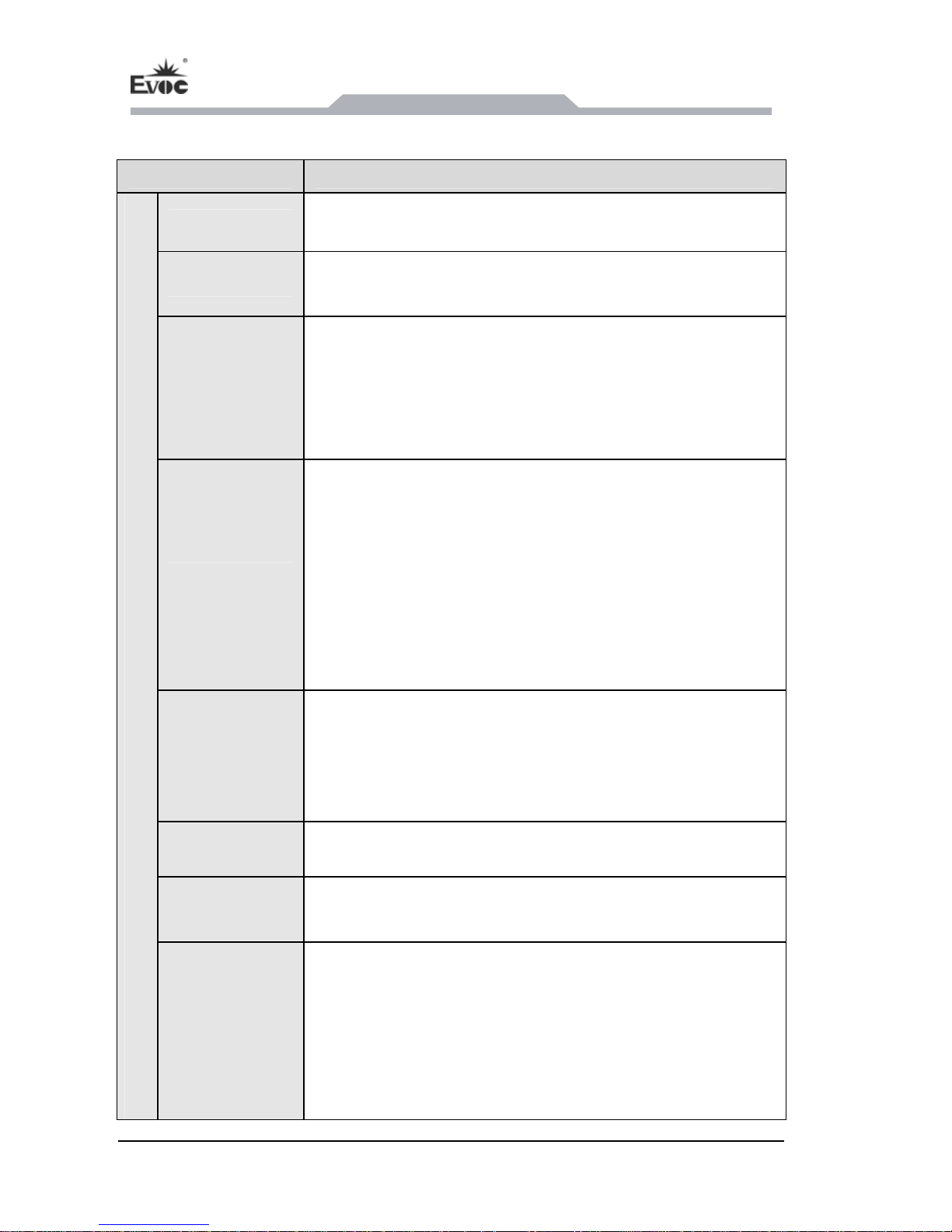
Items Definitions
Microprocessor Intel® Core™ i5-520E CPU in BGA 1288 package on-board
Chipset Intel® QM57
Memory
2G 1066MHz memory on-board, providing one 204Pin
SO-DIMM DDR3 memory slot additionally with
Un-buffered and NON-ECC function; the maximum memory
capacity supported by a single memory slot is up to 4GB.
Expansion Bus
EVOC EPE 1.0 bus, supporting PCIe and PCI bus expansion,
which is expandable to two PCI cards and one PCIe x16 by
carrier, EPE-6104E1-JEC; the PCI card supports 106.6 mm
in height and 174.6mm in length (excluding the slot cover).
PCI 2.3 bus standard compliant.
Note: The power of PCIE expansion slot is no more than
25W, if PCIeX1 expansion card is used, the compatibility
between the expansion card and PCIeX16 slot must be
verified.
LCD Feature
LCD screen: 15″ TFT LCD;
Connector: LVDS;
Resolution: 1024x768;
Luminance: 400cd/m
2
;
Contrast: 700:1
Touchpad Integrated touchpad, left key and right key
Keyboard 87-key plastic keyboard
Main Functional Index
External IO
Connectors
Two serial ports: support RS-232/RS-422/RS-485
mode selection; COM1 supports Modem wake-up
function;
Four USB2.0 ports;
One VGA connector;
Two Gigabit LAN ports;
One PS/2 connector
Page 9
Product Introduction
JEC-1503C - 3 -
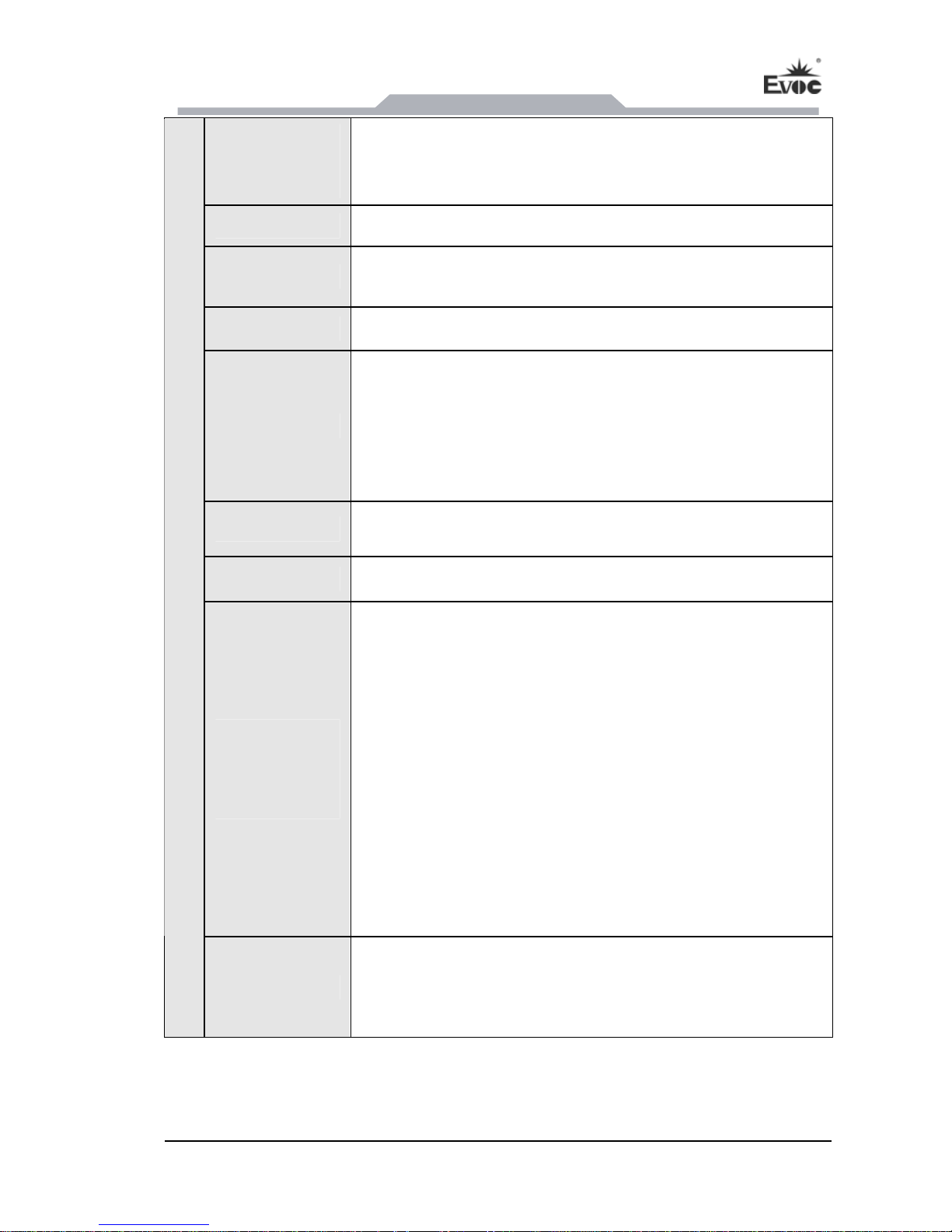
Dimensions
(excluding the
hangers)
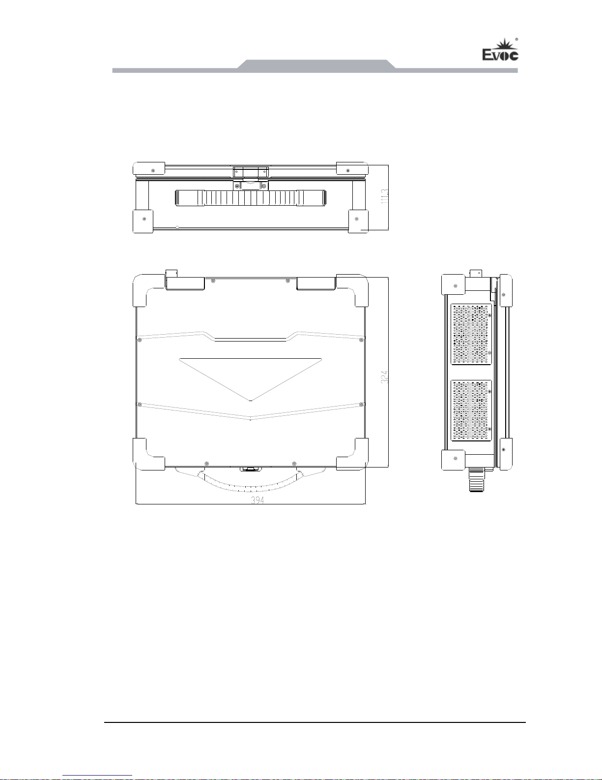
394mm (W) x 111.3mm (H) x 324mm (D)
Weight 8.9Kg
Temperature
Operating Temperature: -20°C ~ 60°C;
Storage Temperature: -40°C ~ 60°C;
Humidity 5%~95% (non-condensing)
EMC
Limits of radio disturbance are compliant with
GB9254-2008, class B;
Limits of immunity are compliant with the threshold of
GB/T 17618-1998;
Meets the requirements of the five items in GJB151A
for land force.
Reliability
MTBF≥50000h
MTTR≤0.5h
Safety Meets the basic requirements of GB4943;
Mechanical
and
Environment
Adaptability
Sinusoidal Vibration (mechanical hard disk): 6 ~
200Hz/1.5g, three axes, 15min/direction. The product is
operating during testing.
Sinusoidal Vibration (SSD hard disk): 5 ~ 30Hz/1.2g,
30 ~ 50Hz/0.3mm, 50 ~ 500Hz/3.0g, three axes,
15min/direction. The product is operating during
testing.
Random Vibration (mechanical hard disk):
Frequency Hz PSD(g2/Hz) dB/oct
5 ~ 200Hz 0.02 ----200 ~ 1000Hz ----- -3
Three axes, 30 minutes per direction.
Anti-shock: 20g acceleration, 11ms duration.
Main Performance Index
Power Feature
Input voltage/frequency: 100-240VAC 50/60HHz;
Power consumption of the PC: 29.4W (standby); power
consumption of the PC: 72.8W (100% operates
MaxPower).
Page 10
Application Scheme
- 4 - JEC-1503C
2. Application Scheme
2.1 Transportation
During long distance transportation, well-packaged products should not be put in open
cabin or carriage. During transshipping, products should not be stored in open air
without protection from the atmospheric conditions. Products should not be
transported together with inflammable, explosive and corrosive substances.
2.2 Storage
Products should be stored in original package box when it is not used. And warehouse
temperature should be 0°C ~ 40°C, and relative humidity should be 20% ~ 85%. In
the warehouse, there should be no harmful gas, inflammable, explosive products, and
corrosive chemical products, and strong mechanical vibration, shock and strong
magnetic field interference. The package box should be at least 10cm above ground,
and 50cm away from wall, thermal source, window and air inlet.
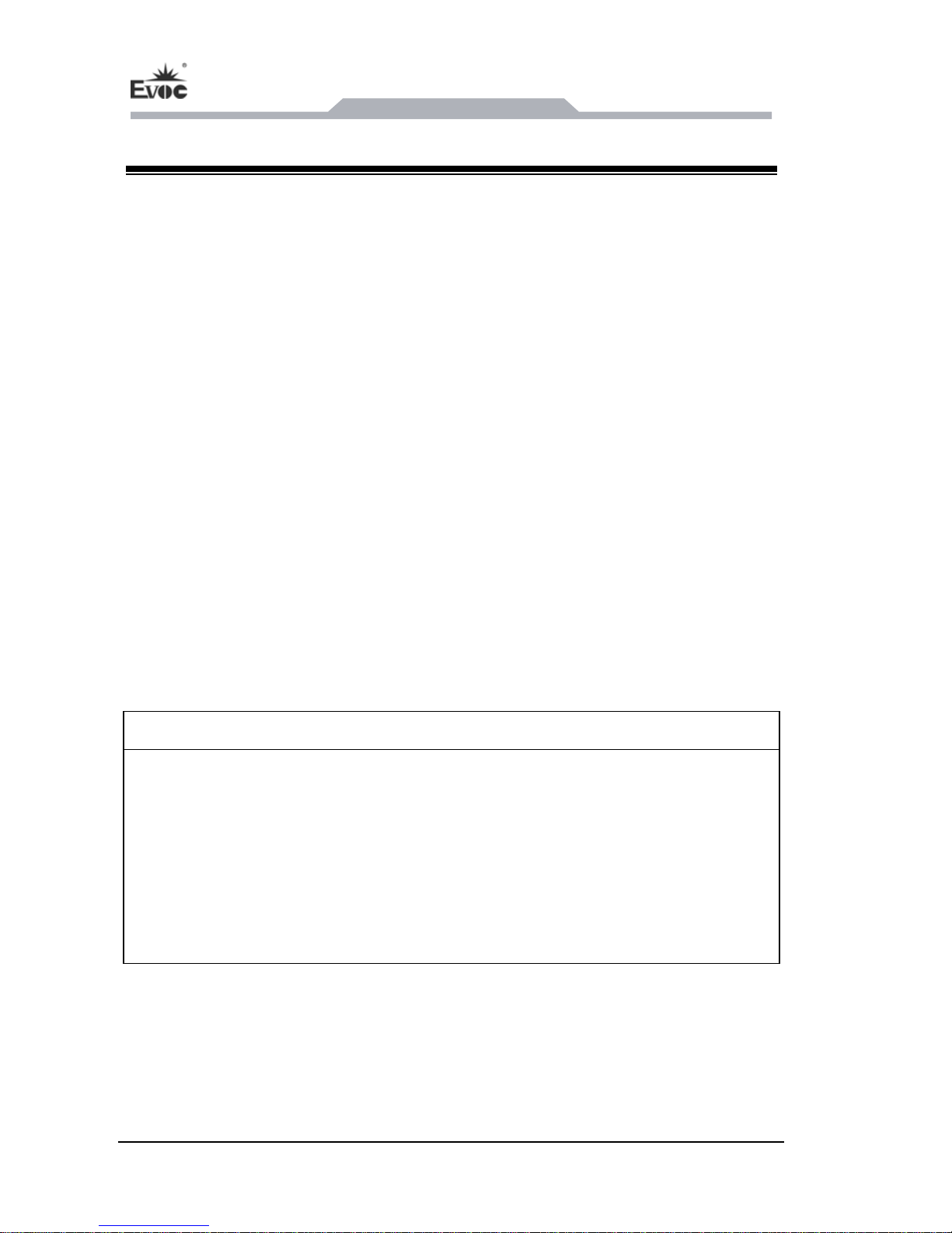
Caution
Risk of destroying the device!
When shipping the PC in cold weather, please pay attention to the extreme
temperature variation. Under this circumstance, please make sure no water
drop (condensation) is formed on the surface or interior of the device. If
condensation is formed on the device, please wait for over twelve hours before
connecting the device.
2.3 Opening the Box and Initial Examination
Opening the Box
Please pay attention to the following issues when opening the box:
Page 11

Application Scheme
JEC-1503C - 5 -
● Do not discard the original packing material. Please keep the original packing
material for re-transportation.
● Please keep the documentation at a safe place. The documentation is required for
initial device debugging, which is a component of the device.
● When doing the initial examination, please check whether there are distinct
damages to the device caused during the transport.
● Please check whether the delivery contains the intact device and all of the
independently ordered accessories. Please contact the customer service when any
unconformity or transportation damages occur.
Page 12
Device Connection
- 6 - JEC-1503C
3. Device Connection
3.1 Notices before Connection
Warning
Peripherals with reverse polarity must not be connected or built-in.
Warning
The device only operates when connected with grounded power. No operation is
allowed when the device power is ungrounded or only impedance is grounded.
Warning
Rated voltage of the device in use shall be in accord with power feature of the
product.
Note:
Only the peripheral devices approved for industrial application can be used. When
operating the PC, hot swappable IO modules (USB) can be used. The IO devices
without hot swap function can only be connected when the PC is powered off.
3.2 Product Grounding
Low impedance ground connection is more helpful to release the interference
produced by the external cables, the signal cables or the cables connecting the IO
module to the grounding system.
Page 13
Device Connection
JEC-1503C - 7 -
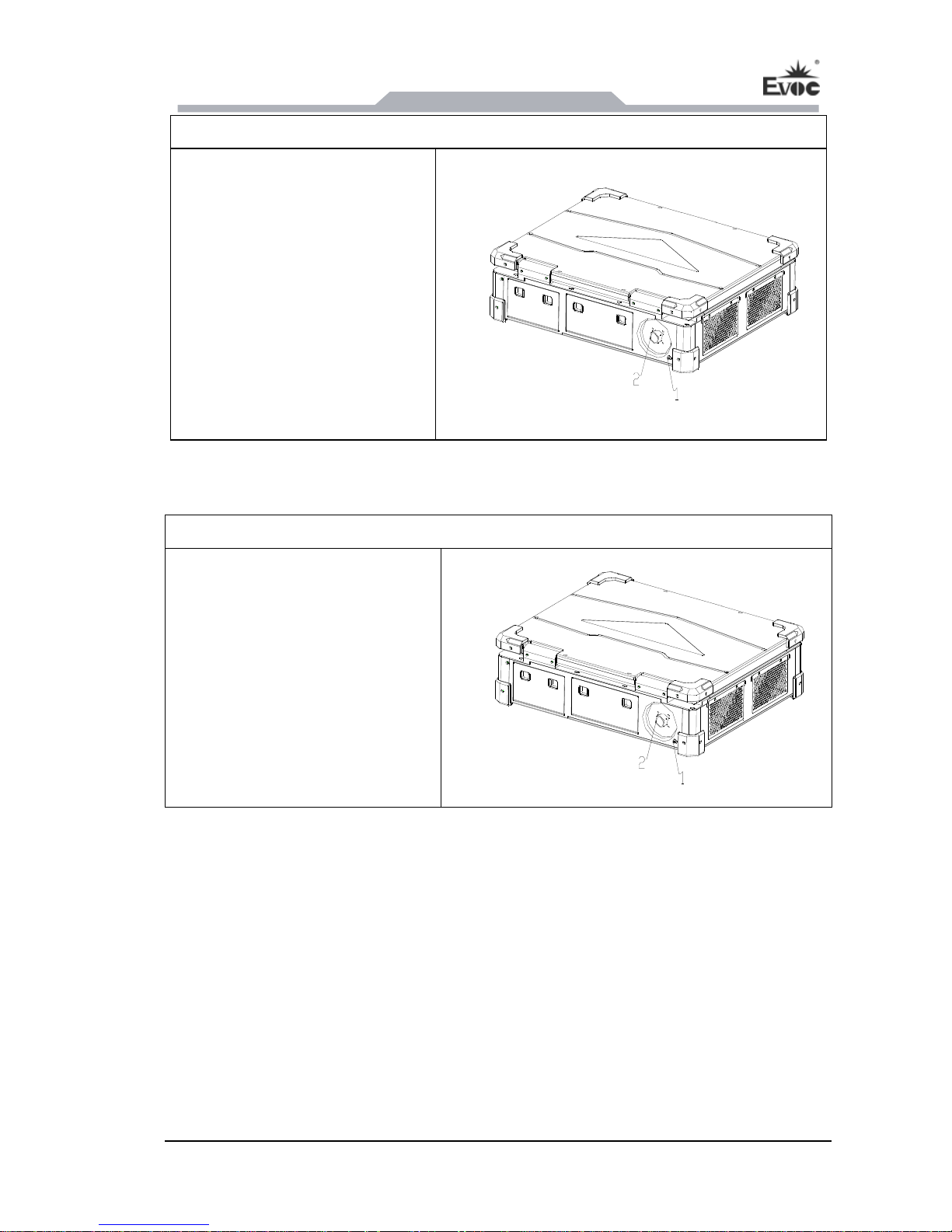
Ground Terminals
The equipotential bonding
terminal 1 on the device (large
surface or large area contact)
shall be connected with the
cabinet installed with the PC or
the central grounding busbar on
the device. The minimum cross
section area of the cable shall be
no less than 5mm
2
.
3.3 Connecting the Device to Power
Steps to connect the device to power:
Please connect the power cord
with connector 2. Please make
sure whether the input voltage is
in accord with the instructed
voltage on the silkscreen of the
power socket before installation.
Page 14
Instructions
- 8 - JEC-1503C
4. Instructions
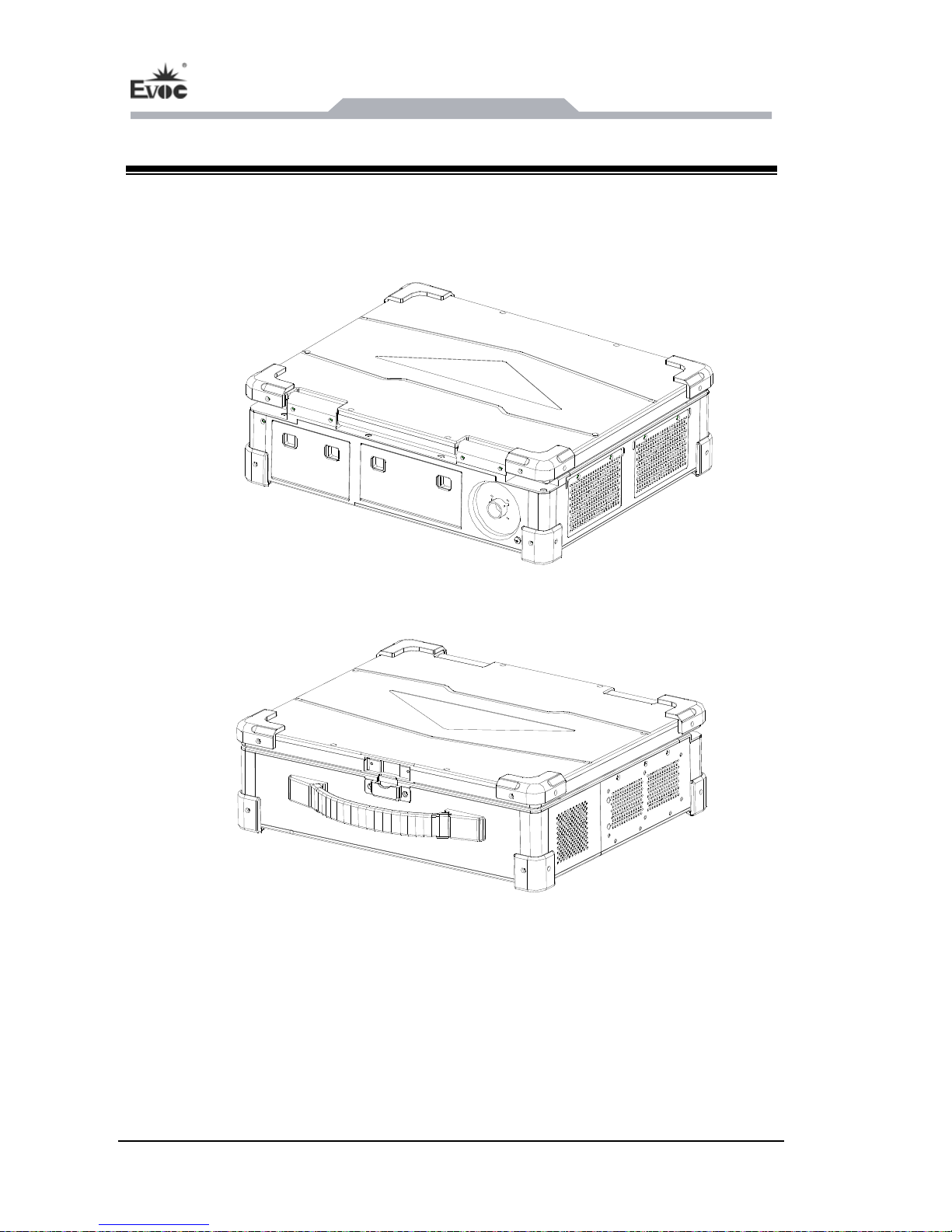
4.1 Product Outline
Page 15
Instructions
JEC-1503C - 9 -
4.2 Product Appearance and Installation Dimensions
Unit: mm
Page 16
Instructions
- 10 - JEC-1503C
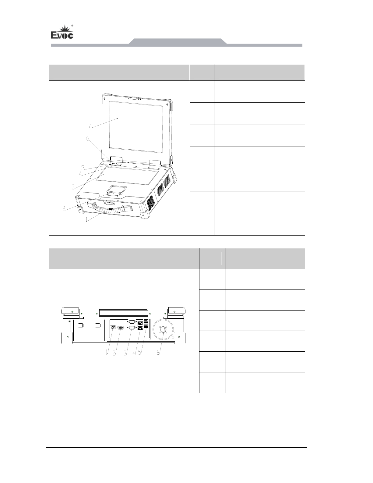
4.3 External Structure
Front View of the Device Item Description
1 Handle
2 Touchpad
3 Keyboard
4 HDD LED indicator
5 PWR LED indicator
6 Power switch
7 LCD screen
Rear View of the Device Item Description
1 MS/KB
2 VGA
3 COM 1/2
4 LAN 1/2
5 USB1/2/3/4
6 AC220V power input
Page 17
Instructions
JEC-1503C - 11 -
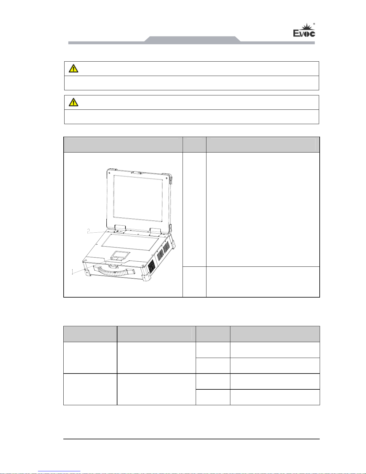
4.4 Operation Control
Warning
Pressing On/Off button won’t cut off the power of the PC!
Caution
Data loss might occur when implementing hardware reset on PC.
Control Button Item Description
1
Touch mouse, left/right button
It is designed as fingertip operation.
Do not place any object on the
surface or press with sharp point
object (such as fingernail) or hard
object (such as pencil or ball point
pen) so as to avoid any scratches on
the surface. Please keep the
touchpad away from hazardous
substances, such as oil, otherwise
the cursor may not operate
normall
y
.
2
Power switch
The button is used to power on or
power off the device.
4.5 Status Indicator
Display Meaning LED Description
Off Power off
POWER Indicates PC status
Green PC is operating
Off No access
HDD Indicates HDD access
Yellow Accessing
Page 18
Instructions
- 12 - JEC-1503C
Danger
Please disconnect the power and data cables during thunder storm.
Note:
To completely isolate the device from the power supply, please disconnect the
power connector.
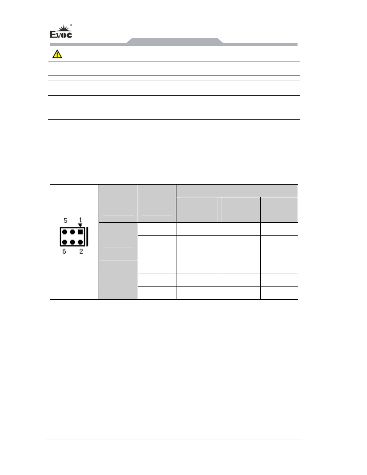
4.6 COM Setting
COM1 and COM2 fully comply with RS-232/RS-422/RS-485 mode, which can be
realized by settig JP1 ~ JP6. Please set as follows:
Mode Selection
COM
Port NO.
Pin
Setting
RS-232
(Default)
RS-422 RS-485
JP1 1-2 5-6 3-4
JP2 1-3, 2-4 3-5, 4-6 3-5, 4-6
COM1
JP3 1-3, 2-4 3-5, 4-6 3-5, 4-6
JP4 1-2 5-6 3-4
JP5 1-3, 2-4 3-5, 4-6 3-5, 4-6
JP1 ~ JP6
COM2
JP6 1-3, 2-4 3-5, 4-6 3-5, 4-6
Page 19
Assem
bly and Maintenance
JEC-1503C - 13 -
5. Assembly and Maintenance
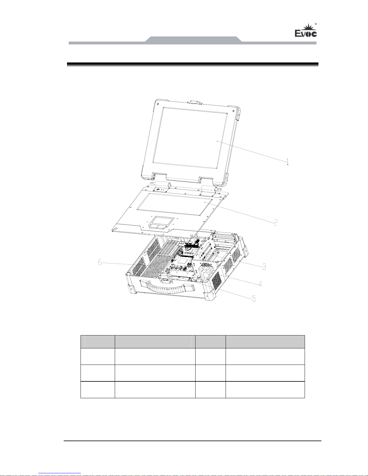
5.1 Overall Assembly Drawing
Item Description Item Description
1 Screen assembly 2 Keyboard assembly
3 Motherboard assembly 4 Chassis assembly
5 HDD assembly 6 Power supply
Page 20
Assembly and Maintenance
- 14 - JEC-1503C
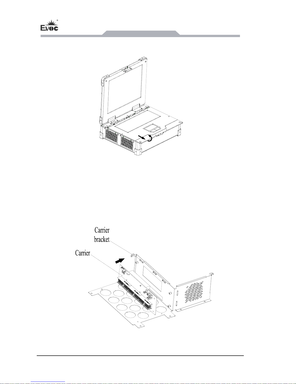
5.2 Removing the Cover
1. Take out the screw caps and the screws on the cover of the host first;
2. Host cover the figure shown by the arrow after the first out, and then flipped up.
5.3 Removal/Installation of Motherboard
5.3.1 Installing the Motherboard
1. Locate the carrier at the corresponding position on the carrier bracket and fix with
screws as shown in the above figure;
Page 21
Assem
bly and Maintenance
JEC-1503C - 15 -
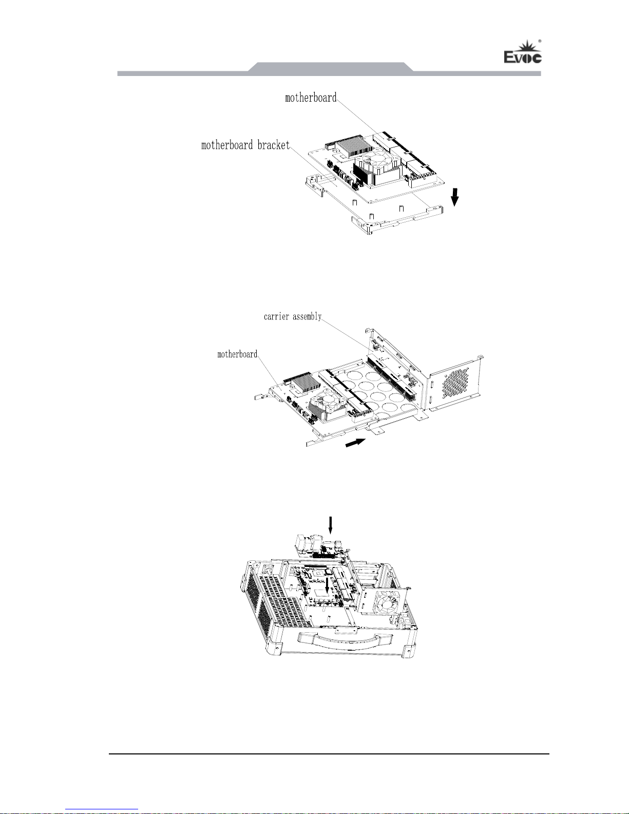
2. As shown in the picture above, install the motherboard properly onto the
motherboard bracket, and fasten it with screws;
3. Insert the motherboard assembly by the correct direction into the carrier board slot
to form an assembly.
4. Place the assembly properly into the chassis, and fasten it with screws and nuts;
5. Install the IO plate by the direction shown in the picture, and insert the cables
connecting with motherboard and carrier baord.
Page 22
Assembly and Maintenance
- 16 - JEC-1503C
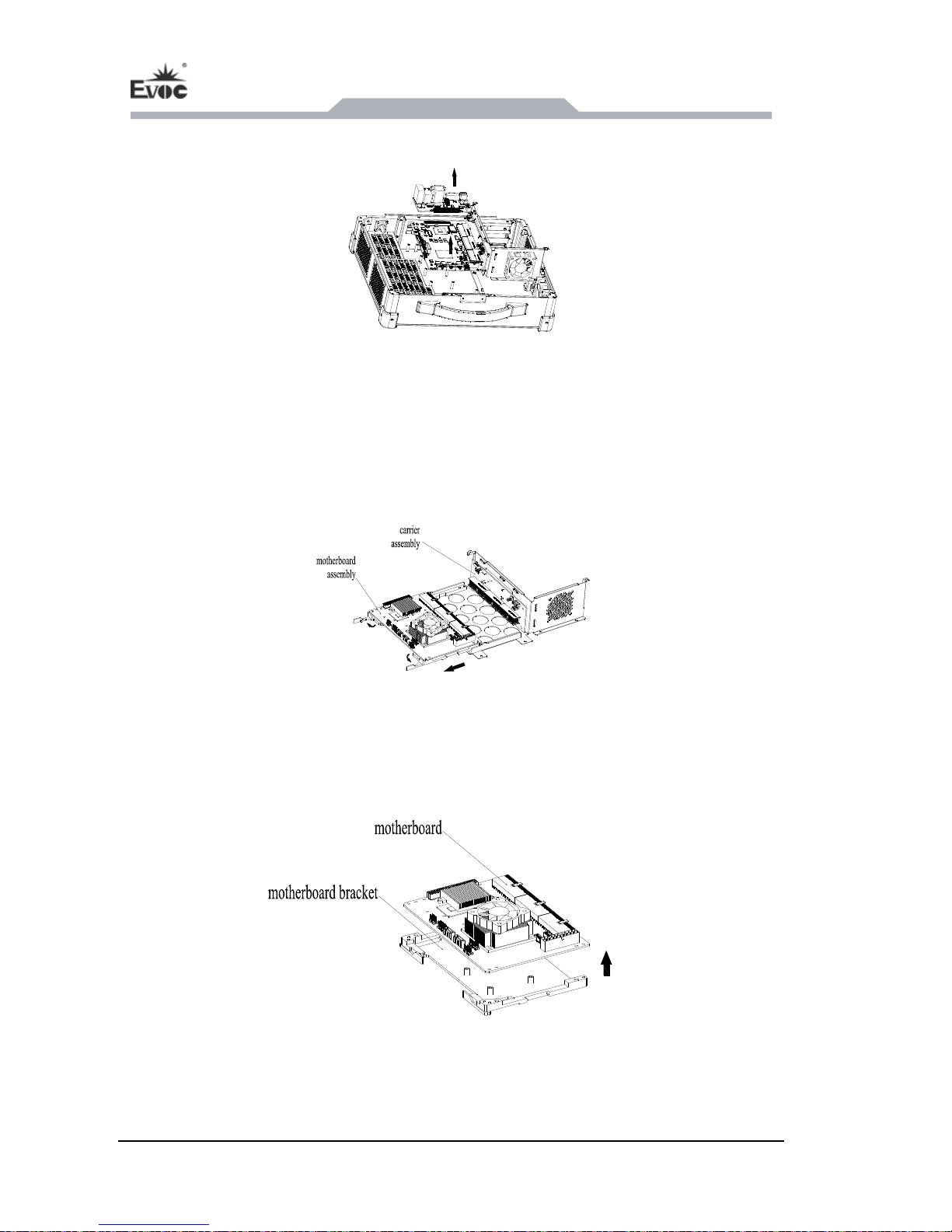
5.3.2 Removing the Motherboard
1. Remove the cables connecting with the motherboard and carrier, take out the IO
board in the direction shown in the figure;
2. Remove the screws and nuts fixing the motherboard and carrier bracket;
3. Take out assembly (with motherboard, carrier and carrier bracket);
4. Turn the spanner by the direction shown in the picture above, and pull out the
motherboard assembly from the slot;
5. Take out the screws fixing the motherboard as per the picture above, and remove
the motherboard from the bracket.
Page 23
Assem
bly and Maintenance
JEC-1503C - 17 -
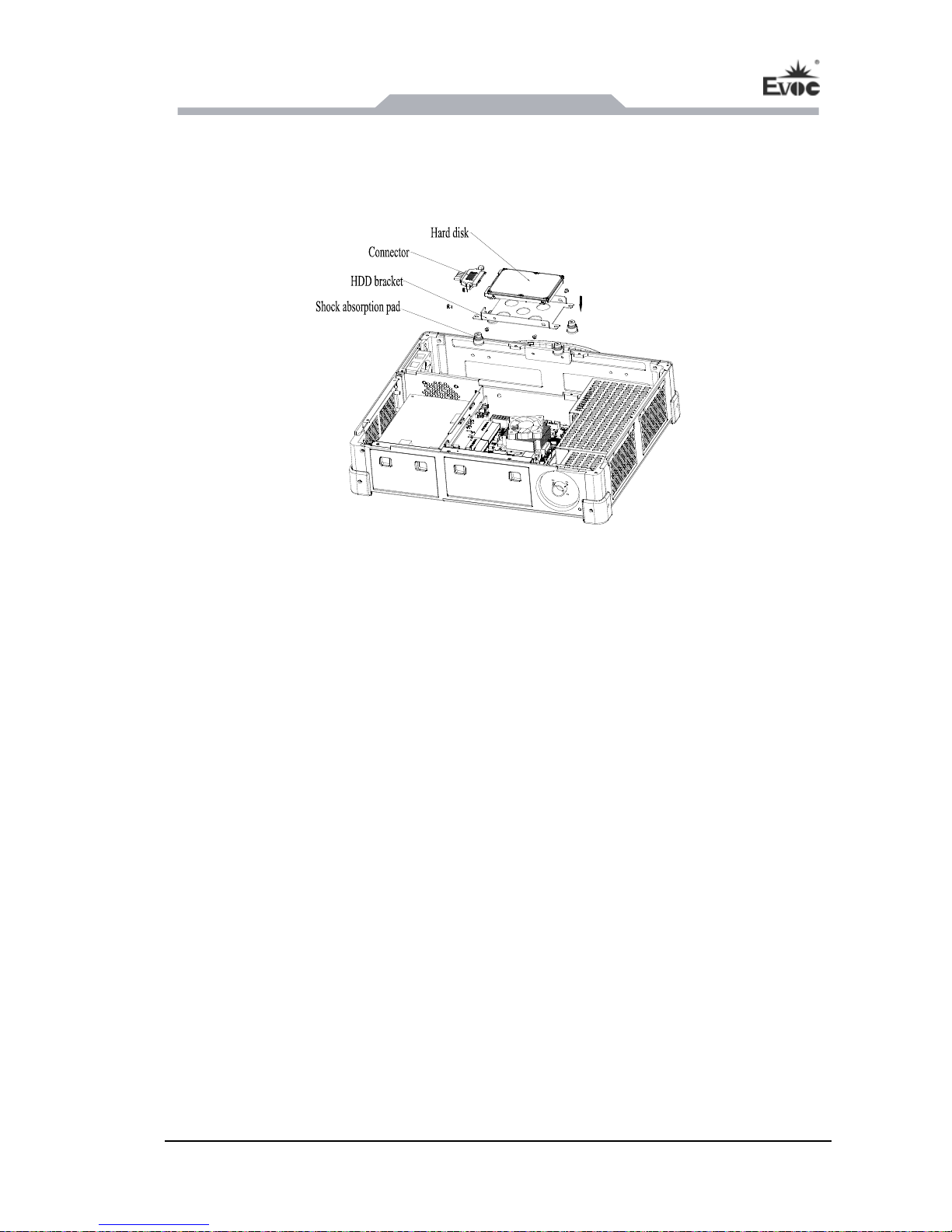
5.4 Removal/Installation of Driver
5.4.1 Installing the Hard Disk
1. Connect the SATA connector with the hard disk and then put them on the hard disk
bracket;
2. Fix the connector and the hard disk on the hard disk bracket with screws to form
hard disk assembly;
3. Fix the shock absorption pads at the corresponding positions in chassis and then fix
the hard disk assembly on the shock absorption pads with screws.
5.4.2 Removing the Hard Disk
1. Remove the screws fixing the hard disk bracket to take out the hard disk assembly;
2. Remove the screws fixing the hard disk and then draw out the hard disk.
Page 24
Assembly and Maintenance
- 18 - JEC-1503C
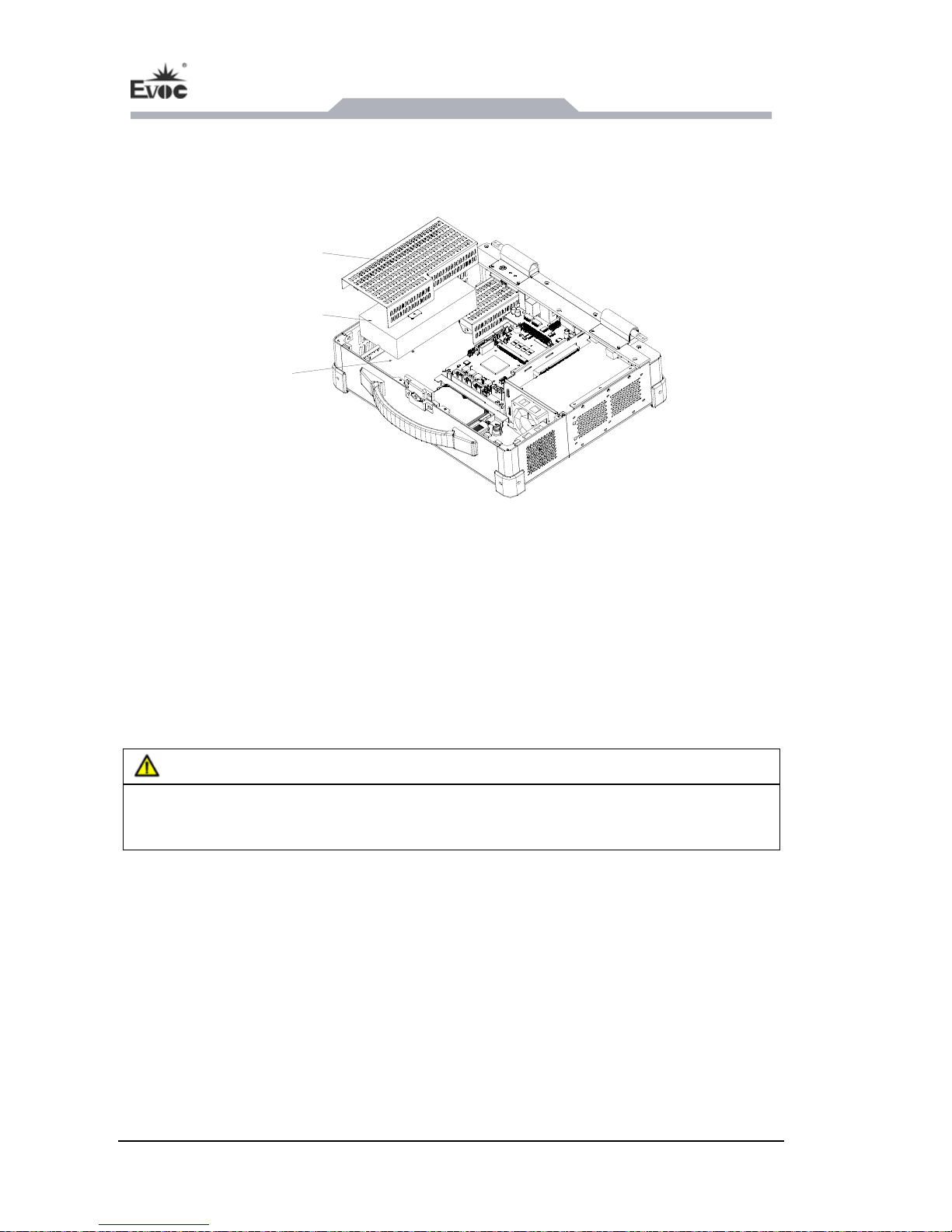
5.5 Removal/Installation of Power Supply
5.5.1 Installing the Power Supply
Power supply
cover
Power supply
Carrier
1. Locate the power supply at the corresponding position in chassis and fix with
screws;
2. Connect with cables;
3. Install the power supply cover according to the figure and fix with nuts.
5.5.2 Removing the Power Supply
Danger
Before removing the power module, please turn off the power and remove the power
cord if any power has been connected.
1. Remove the nuts and take off the power supply cover;
2. Unplug the cables;
3. Remove the screws fixing the power supply and then take out the power supply.
Page 25
Assem
bly and Maintenance
JEC-1503C - 19 -
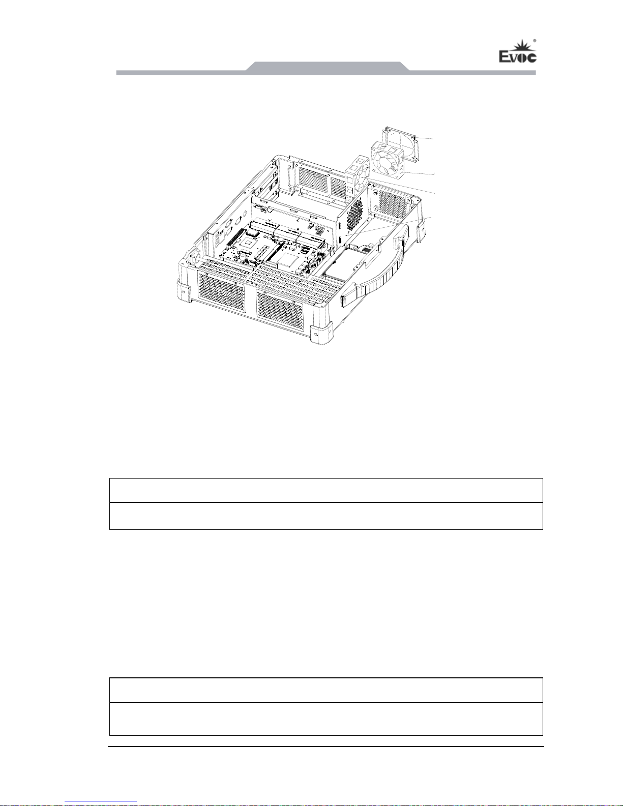
5.6 Assembly and Maintenance of Fan
5.6.1 Installing the Fan
Fan bracket
Fan 2
Fan 1
Carrier bracket
1. Fix fan 1 with fan bracket by screws;
2. Locate the fan assembly at the corresponding position in chassis and fix with
screws;
3. Locate fan 2 at the corresponding position on the carrier bracket and fix with
screws.
Note:
Because the fan speed is relatively fast, please do not touch the fan before it stops.
5.6.2 Removing the Fan
1. Remove the screws and then take off fan 2 from the carrier bracket;
2. Remove the screws and then take off the fan assembly from the side wall of the
chassis;
3. Remove the screws and then take off fan 1 from the fan bracket.
Note:
Because the fan speed is relatively fast, please do not touch the fan before it stops.
Page 26
Assembly and Maintenance
- 20 - JEC-1503C
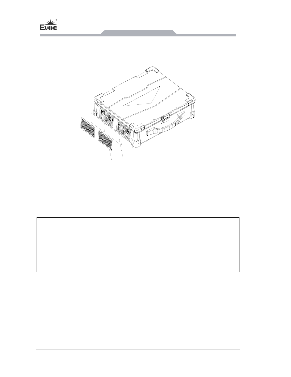
5.7 Assembly and Maintenance of Dust-proof Net
5.7.1 Installing the Dust-proof Net
Host
Dust-proof net
Dust-proof
net cove
r
1. Put the dust-proof net into the corresponding slot on the side wall of the chassis;
2. Insert the dust-proof net cover into the slot on the side wall and then fix with
screws.
Note:
To ensure excellent system heat dissipation and ventilation and avoid the dust-proof
net covered with dust, please clean the net regularly. It is recommended to clean it
every three months. In an environment prone to dust or dirt, please clean the net more
frequently. The dust-proof net should be replaced once a year.
5.7.2 Removing the Dust-proof Net
1. Remove the screws and then pull out the dust-proof net cover from the slot on the
side wall;
2. Take out the dust-proof net from the corresponding slot on the side wall of the
chassis.
Page 27
Assembly and Maintenance
JEC-1503C - 21 -
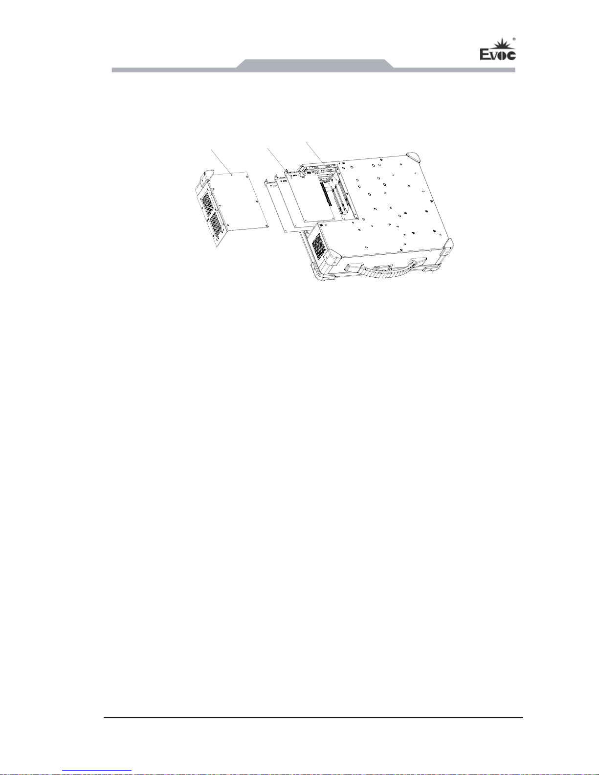
5.8 Installation of PCI/PCI-E Expansion Card
1. Remove the screws fixing the expansion door
cover and then pull out the cover as
shown in the above figure;
2. Insert the PCI or PCI-E card into the corresponding slot on carrier and fix the slot
cover with screws;
3. Put on the expansion door cover and tighten the screws.
PCI/PCI-E
card
Carrie
r
Expansion d
cove
oor
r
Page 28

Installing the Drivers
- 22 - JEC-1503C
6. Installing the Drivers
Regarding the installation of the driver program and the detailed information of the
motherboard, please refer to the enclosed CD of the PC.
Page 29
Appendix
JEC-1503C - 23 -
7. Appendix
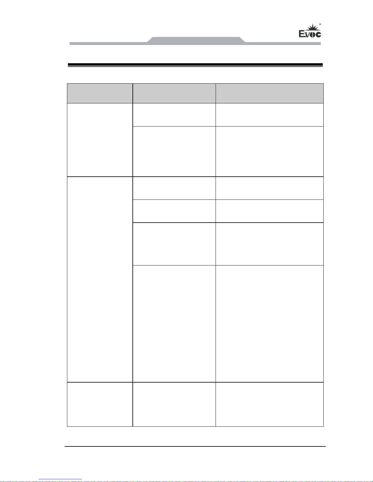
7.1 Troubleshooting and Solutions
Common
Malfunctions
Reasons Troubleshooting and Solution
No power supply
Please check the power supply
and the power cable/connector.
The device is not
operating
Improper device
operating environment
1. Check with the environment
conditions;
2. Please wait for twelve hours
before powering on the device
shipped in cold weather.
The display has not been
turned on
Turn on the display.
The display is under
“power saving” mode
Press any key on the keyboard.
The luminance control is
set to “Black”.
Increase the screen luminance by
luminance control. Please refer to
the instructions of the display for
detailed information.
The external
display is black
Power cable or display
cable is not connected
1. Please check whether the
power cable is correctly
connected with the display, the
system unit or the ground port.
2. Please check whether the
display cable is correctly
connected with the display and
the system unit.
3. Contact Technique Support if
the screen remains black after
implementing the above
measures.
Incorrect time or
date on PC
Incorrect BIOS setting
Follow the power-on prompt and
press the key to enter the BIOS
Setup; adjust the time and date in
BIOS Setup.
Page 30
Appendix
- 24 - JEC-1503C
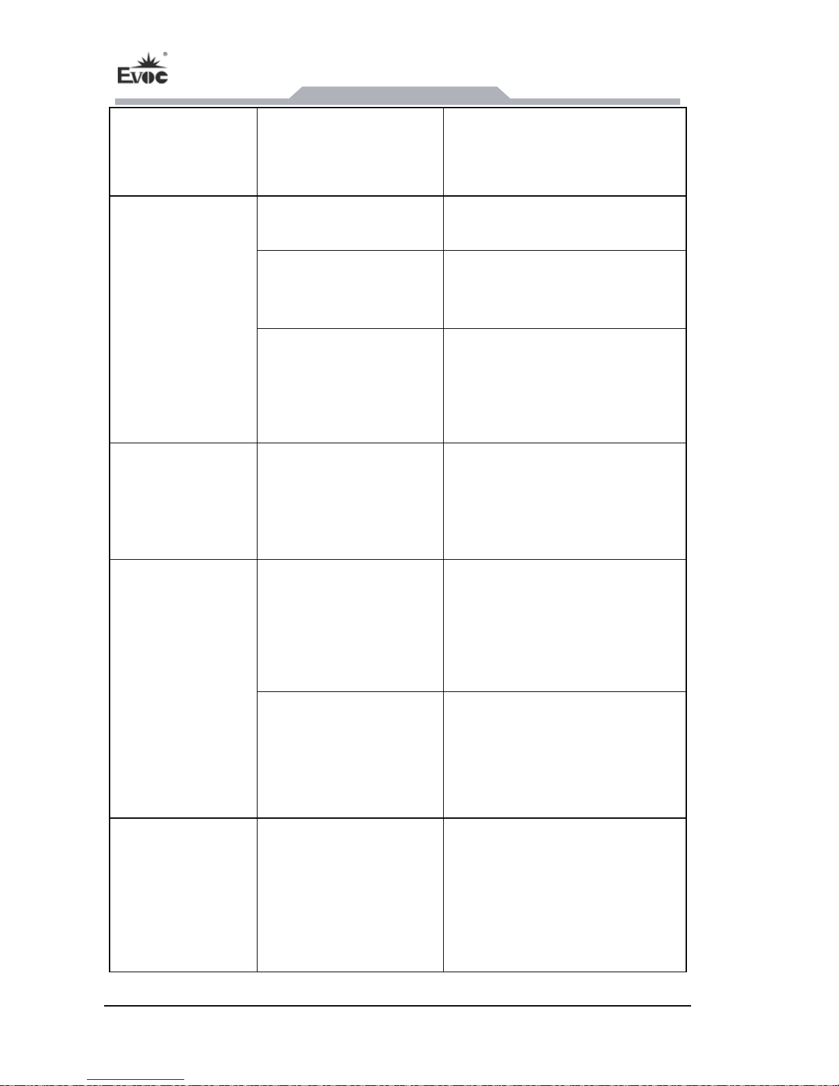
BIOS setting is
correct while the
time and date are
incorrect.
Insufficient backup
battery capacity
Replace the battery
USB port is disabled in
BIOS
Use other USB ports or enable
that port.
USB 2.0 device is
connected; however,
USB 2.0 is disabled.
Enable USB 2.0.
USB device has no
response
USB port is not
supported by the
operating system.
1. Enable USB Legacy Support
for the mouse and keyboard
(Legacy USB is supported);
2. For other devices, appropriate
USB drivers are required.
The computer is
not booted or
displays “Boot
device not found”
In booting priority of the
BIOS setting, the device
is not the first priority or
the device is not include
in the booting device.
Modify the booting priority of the
device in the Boot menu of BIOS
setting or include that device into
the booting priority.
The HDD power cable or
data cable is not
connected well
Check whether the power cable
and the data cable of the hard
disk (the hard disk shall be
installed with operating system
and is bootable) are well
connected.
No system disk
can be found when
powering on
System files on the hard
disk are damaged
Enter the system (usually WinPE
system) with a bootable disk;
check whether the system in the
hard disk is damaged. Reinstall
the system if necessary.
Plug and play I/O
card, no IO card is
detected or no IO
card can be used
when used again
Poor contact of the slot
Poor contact is usually caused by
frequent installation/
uninstallation of the PCI or ISA
card, unstable fixing or improper
dust-proof measures; please
remove and install the card for a
few times or use another slot.
 Loading...