

Page 1
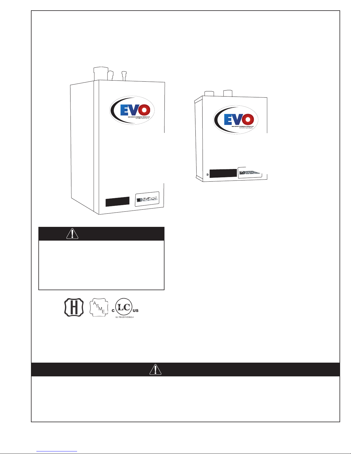
Installing, Operating & Maintaining
EVO 79–599 HIGH EFFICIENCY
WATER HEATERS AND HEATING BOILERS
EVO 299–599
300,000 BTU/hr
399,000 BTU/hr
630,000 BTU/hr
WARNING
If the information in this manual
is not followed exactly, a re or
explosion may result causing
property damage, personal
injury or death.
EVO 79–199.1
80,000 BTU/hr
136,000 BTU/hr
180,000 BTU/hr
199,000 BTU/hr
Do not store or use gasoline or other
ammable vapors and liquids in the vicinity
of this or any other appliance.
WHAT TO DO IF YOU SMELL GAS:
• Do not try to light any appliance
• Do not touch any electrical switch
• Do not use any phone in your building
Immediately call your gas supplier from a
neighbor’s phone. Follow the gas supplier
instructions. If you can not reach your gas
supplier, call the re department.
ANSI Z21.13-2014/CSA 4.9-2014
UL 795-2011/CSA 3.4
SCAQMD 1146.2
New York Massachusetts SCAQMD CEC Listed
MEA 425-05-E Boilers: G1-06-06-24A Compliant Rule1146.2 California Energy Commission
Heaters: G1-06-06-24B
These appliances MUST be installed by a properly licensed individual in the City and State which the unit is
being installed. All start up adjustments and subsequent service work must be done by a similarly licensed
contractor or a factory trained service individual. Failure to comply could result in loss of warranty and or
severe personal injury, death and or substantial property damage. These instructions are required to be
kept with the appliance on the left side, in the pocket provided.
34000 Autry Street, Livonia, MI 48150 | 800.968.5530 | Fax 734.419.0209 | www.hamiltonengineering.com | LIT91127US REV 5/2018
WARNING
Page 2
USING THIS MANUAL
USING THIS MANUAL
DANGER
Throughout this manual you will see these
special attention boxes similar to this one,
which are intended to supplement the
instructions and make special notice of
potential hazards. These categories are in the
judgement of Hamilton Engineering, Inc.
WARNING
Indicates a condition or hazard which
MAY cause severe personal injury,
death, or major property damage.
Indicates a condition or hazard which
MAY cause severe personal injury,
death, or major property damage.
CAUTION
Indicates a condition or hazard which
MAY cause severe personal injury,
death, or major property damage.
WARNING
• THE VENT SYSTEM IS RATED AND DESIGNED TO BE 2 PIPE SEALED COMBUSTION
ONLY, PVC SCH 40 OR CPVC SCH 40 OR 80 OR AL 29-4C STAINLESS VENTING FOR ALL
MODELS. A FACTORY ENGINEERED VENTING SYSTEM MAY ALLOW FOR EXCEPTIONS;
CONSULT FACTORY FOR DETAILS.
• THIS HEATER INSTALLATION MUST CONFORM TO THE LATEST EDITION OF THE
“NATIONAL FUEL GAS CODE” ANSI Z223.1 NFPA 54 AND/OR CAN/CGAB149
INSTALLATION CODES. STATE AND LOCAL CODES MIGHT ALSO APPLY TO
INSTALLATION.
• WHERE REQUIRED BY THE AUTHORITY HAVING JURISDICTION, THE INSTALLATION
MUST CONFORM TO THE STANDARDS FOR CONTROLS AND SAFETY DEVICES FOR
AUTOMATICALLY FIRED HEATERS, ANSI/ASME HEATER AND PRESSURE VESSEL CODE,
SECTION IV, ALONG WITH CSD-1.
• THE HEATER, GAS PIPING, WATER PIPING, VENTING AND ELECTRICAL MUST BE
INSTALLED BY TRAINED & QUALIFIED PERSONNEL FAMILIAR WITH INSTALLATION
PRACTICES, LOCAL CODE, AND LICENSING REQUIREMENTS.
• IF THE INFORMATION IN THESE INSTRUCTIONS ARE NOT FOLLOWED EXACTLY, A FIRE
OR EXPLOSION MAY RESULT, CAUSING PROPERTY DAMAGE, PERSONAL INJURY, OR
DEATH.
• DO NOT STORE OR USE GASOLINE OR OTHER FLAMMABLE VAPORS AND LIQUIDS IN
THE VICINITY OF THIS OR ANY OTHER APPLIANCE.
34000 Autry Street, Livonia, MI 48150 | 800.968.5530 | Fax 734.419.0209 | www.hamiltonengineering.com | LIT91127US REV 5/2018
Page 2
Page 3

TABLE OF CONTENTS
TABLE OF CONTENTS
Part 1 . . . . . . . . . . . . . . . . . . . . . . . 4-11
GENERAL INFORMATION
A How It Operates 4-5
B EVO Controls 6-8
C EVO Dimensions 9-10
D Pre-installation Requirements 10-11
E Pressure Relief Valve 11
Part 2 . . . . . . . . . . . . . . . . . . . . . . 12-13
ELECTRICAL
A Electrical Connection/Requirements 12
B Internal Wiring Connection 12-13
Part 3 . . . . . . . . . . . . . . . . . . . . . . 14-19
GAS CONNECTION
A Gas Connection 14
B Gas Piping 14
C Gas Tables 15
D Gas Valve Set Up 15-17
E Setting Maximum Load 17-18
F Setting Minimum Load 18
G Gas Conversion 19
H Gas Valve Replacement 19
Part 4 . . . . . . . . . . . . . . . . . . . . . . 20-28
VENTING
A Approved Venting Materials 20
B Venting the EVO 21-26
C Inlet Air Vent 27
D Venting Runs Exceeding Maximum
Combined Length 27
E Heater Removal from a
Common Vent System 27-28
F Condensate Requirements 28
Part 5 . . . . . . . . . . . . . . . . . . . . . . 29-37
PIPING
A Hydronic Heating Boiler Piping 29
B Boiler Schematic Drawings 30
C Fill & Purge Heating System 31
D Removing Air from Heat Exchanger 31
E Water Heating Piping 32
F Water Heater Schematic Drawings 33-37
Part 6 . . . . . . . . . . . . . . . . . . . . . . 38-40
START UP PROCEDURES
A Items to be checked before
lighting the EVO 38
B Lighting Instructions 38-39
C Operating Instructions 39
D Adjusting the Temperature
on the EVO Display 39
E Sequence of Operation 40
Part 7 . . . . . . . . . . . . . . . . . . . . . . . 40-47
SERVICING
A Servicing the EVO 40
B Placing EVO into Normal Operation 40
C Soft Lockout Codes 41
D Hard Lockout Codes 41-42
E Fault Causes 43-44
F To Turn Off Gas to Appliance 46
G Pump & Wiring Control 46
H Temperature Sensor Reading
Instructions 46
I EVO Sensor Resistance Table 47
Part 8 . . . . . . . . . . . . . . . . . . . . . . . 47-64
MAINTENANCE
A Maintenance Procedures 47
B Annual Inspection 48-52
C Condensate Cleaning Instructions 53
D Combustion Chamber
Coil Cleaning Instructions 54-55
E EVO Controls 56
F Coil Scaling Prevention Feature
(E-6 error codes) 57
G EVO 79-199.1 Parts Breakdown 58-60
H EVO 299 -599 Parts Breakdown 61-64
I Universal Wiring Diagram 65
Part 9 . . . . . . . . . . . . . . . . . . . . . . . 66-67
SPECIAL INSTALLATION REQUIREMENTS
A Installation Requirements
(Massachusetts) 66
B Installation at High Altitudes 67
Part 10 . . . . . . . . . . . . . . . . . . . . . . . . 67
WARRANTY INFORMATION
A Warranty Contact Information 67
34000 Autry Street, Livonia, MI 48150 | 800.968.5530 | Fax 734.419.0209 | www.hamiltonengineering.com | LIT91127US REV 5/2018
Page 3
Page 4
GENERAL INFORMATION
PART 1. GENERAL INFORMATION
A. HOW IT OPERATES
The EVO product line is an extremely high efciency water heating product, requiring special venting and
condensate removal precautions. All high efciency condensing appliances will require more maintenance
(cleaning) than their non-condensing counterparts. Failure to do so may result in damage to the appliance that
is not covered under warranty. Failure to follow all of the instructions contained in this manual may also cause
premature product failure that may not be covered under warranty.
This appliance has built-in freeze protection, automatically activating the circulation pump when the internal
water temperature drops below 41°F. If the internal water temperature drops to 37°F, a burn cycle will be initiated
and will shut down as soon as the supply water temperature has reached 50°F. Power and gas must be left on
for this function to operate.
The appliance’s primary controller (FMT 914) operates all functions of needed control and safety. It contains
sophisticated logic that allows it to operate at very precise temperatures while minimizing burner on/off cycling.
When multiple units are operated as a Cascade to handle a common load, the control logic contains the ability
to control all of the units as efciently as one. Cascade operation is a factory-installed and programmed option,
requiring a eld wiring connection between appliances for operation.
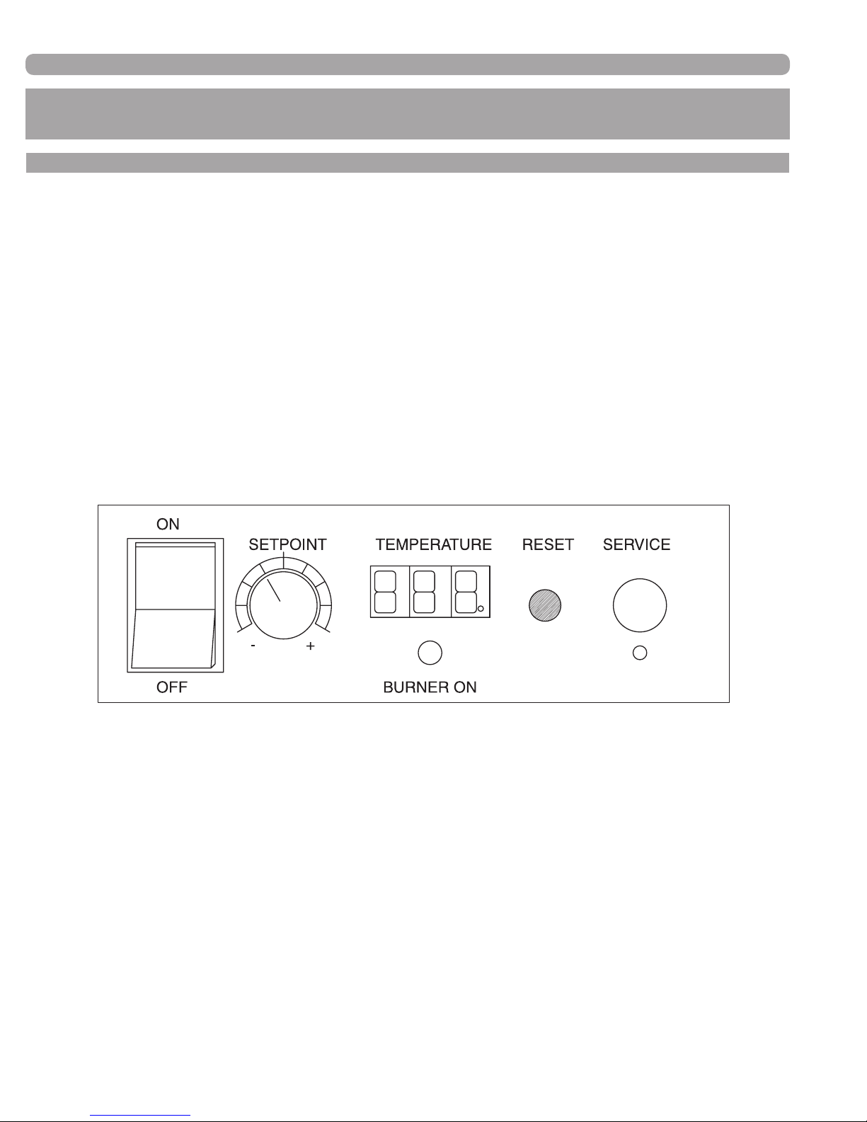
Looking at the controls on the front of the appliance,
1) POWER on/off switch
2) SETPOINT knob, temperature control (and fan speed control knob during service mode)
3) TEMPERATURE setpoint display
a. Temperature in °F, corresponding to the SETPOINT knob
b. Display will always read temperature setpoint unless there is a fault code displayed.
c. Cascade indicator light, found in the lower right hand corner of the Temperature display. This dot will
be ashing when this appliance is part of a properly-connected, commonly-controlled group of EVO
products and reading temperature sensors.
d. Display code, not ashing indicates a Soft Lockout
e. When this display is ashing a code, the appliance is in a Hard Lockout and the reset must be
pushed to re-start the appliance.
4) Green indicating light labeled BURNER ON; when lit, the burner is ring.
5) RESET button, used as described in 3e above, as well as to view sensors and set altitude
(see pages 46 & 64 respectively for details).
6) SERVICE port, used for connecting a computer to the appliance to download the service fault history, as
well as factory setting of control board parameters. There is a service button located just below the
service port that must be pressed with a pointed object to get to the service mode.
34000 Autry Street, Livonia, MI 48150 | 800.968.5530 | Fax 734.419.0209 | www.hamiltonengineering.com | LIT91127US REV 5/2018
Page 4
Page 5
GENERAL INFORMATION
A number of parameters must be programmed at the factory to provide proper operation and temperature
control, including:
• Controlling Sensor: Setpoint, Offset, Hysterese and Bandwidth.
• Controlling sensor is the inlet sensor for a stand alone water heater, outlet sensor for a stand
alone boiler or the remote 10k thermistor for either water heater or boiler any time one is
connected. Connection is automatically detected and control shifted to the remote sensor from
the internal sensor by the EVO Controller when a 10k sensor is connected to the appropriate
terminals.
• Secondary Sensor: Setpoint Outlet and Offset.
• Setpoint: desired operating water temperature (this is set by the end user)
• Offset: amount the temperature is allowed to go above Setpoint before nally shutting off
• Hysterese: amount the temperature is allowed to drop under Setpoint plus offset before the
appliance turns on
• Bandwidth: the range over which ame modulation occurs (this only takes place below Setpoint)
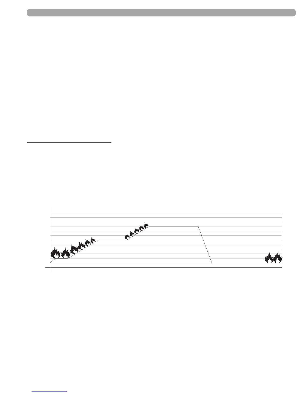
EXAMPLE: Water Heater Control
Controlling sensor
All of the following parameters are controlled by either a storage tank temperature sensor or the inlet temperature
sensor:
• Setpoint = Target Temperature (120°F) Low re only above this point
• Offset = Off Setpoint (3) = 123°F off
• Hysterese = On Setpoint (8) (120 + 3 - 8 = 115°F)
• Bandwidth = Modulation range (4) (120 - 4 = 116°F, modulation begins)
126°
125°
124°
123°
122°
121°
120°
119°
Temperature
118°
117°
116°
115°
Low Fire
Setpoint
Modulation Range
Bandwidth
Setpoint + Offset
Burner Off
Burner On
Setpoint + Offset - Hysterese
The heater turns on at 115°F and when the temperature reaches 116°F the ame will begin to modulate down
(approximately 25% of the modulation range per degree F of increase in this example) at 120°F, it will be at low
re and will remain there unless the temperature drops below 120°F and it will modulate back up. If it continues
to increase, it will shut down at 123°F.
Outlet sensor
Its purpose is twofold: rst stage as a high limit and second as a sensor for computing ∆T. Default water heater
settings are as follows:
• Setpoint = start of modulation (185°F)
• Offset = Off Setpoint (5°F) (185 + 5 = 190°F off)
There is a xed Manual Reset High Limit at 198°F (155°F and 210°F also available) on water heaters and
heating boilers.
34000 Autry Street, Livonia, MI 48150 | 800.968.5530 | Fax 734.419.0209 | www.hamiltonengineering.com | LIT91127US REV 5/2018
Page 5
Page 6

GENERAL INFORMATION
B. EVO CONTROLS
The following is an overview of the EVO controls. More detailed descriptions of EVO congurations can be found
in LIT91110 - FMT-914 Control Congurations.
Control Sensors - Control of the EVO will require the use of appropriate internal and external control
sensors (all 10k ohm):
• Flow - this is the internal leaving water from the heater/boiler.
• Return - this is the internal entering water to the heater/boiler.
• External - this is the storage tank sensor on water heaters and the common loop/low loss
header sensor on boilers.
• Indirect Sensor - this is the Domestic Hot Water tank sensor on a heating boiler application only.
• Outdoor - the is the sensor to be mounted outdoors for temperature reset control on a heating
boiler application only.
Pump Control - All water heaters and boilers are designed to operate with their own individual pump that
will be controlled, on/off, by the EVO controller. The controller runs the pump for a xed period of time
after the end of a burn cycle and uses the combustion air fan as the cooling medium to ONLY cool the
heat exchanger. This is accomplished by monitoring the inlet and outlet water temperature sensors and
running the fan until they are within a pre-set range.
Cascade Control - When multiple units are operated as a Cascade system to handle a common
load, the EVO controller contains the ability to control up to 8 burners as efciently as one.
Common Venting - When units are installed as a Cascade system and a factory-supplied common venting
manifold is used, the software contained in the controller provides for accurate, fail-safe control of all
units in the Cascade while using a single air supply and single exhaust, for up to (8) burners. In addition
to this software, hardware that is standard in each unit, makes venting of multiple units in a positive pressure
venting system a reality.
Control of ring rate - The EVO controller contains sophisticated logic that allows it to operate at very
precise temperatures while minimizing burner on/off cycling. Whether the temperature setpoint is manually
set, sent via BMS as 0 – 10 VDC signal, or calculated via the outdoor reset function, precise temperatures
are the standard. The difference between the temperature set-point and the water temperature sensed
at the control sensor and how quickly the temperature is moving to or away from that desired water
temperature are the basis for the control response.
Domestic Water Heating (DHW) - This controller is the only one of it’s kind in use in North America
that contains separate software for DHW and Central Heating. Safeties, control response and other
operational considerations are unique to DHW applications, including concerns of scaling due to poor
water conditions. The EVO controller was designed from the ground up with this application in mind.
It is recommended to use an external sensor located in the storage tank for control in DHW applications.
If an external temperature sensor is not used, the EVO will be controlled by its own inlet (Return) sensor and
the water heater pump must run constantly.
34000 Autry Street, Livonia, MI 48150 | 800.968.5530 | Fax 734.419.0209 | www.hamiltonengineering.com | LIT91127US REV 5/2018
Page 6
Page 7

GENERAL INFORMATION
B. EVO CONTROLS CONT.
Central Heating - The EVO controller has many built-in functions for precise control in Central Heating
applications. The controller can operate on its own internal Flow (outlet) sensor, however the preferred
method is to use an External Sensor connected to the Lead Boiler. If the External Sensor is not
employed, the boiler(s) will need to have a constant ow of water so that the internal sensors can accurately
detect the loop temperature.
When the External sensor is installed in the main building loop or a Hamilton System Separator (low loss header),
the boiler system operates at peak efciency, reducing short-cycling and maintaining a constant loop temperature.
The External Sensor must be installed in a location that has good water ow - avoid positions where the sensor
will be located in stagnant ow areas or in the near boiler piping. See LIT91110 - FMT-914 Control Congurations
for suggested locations.
In a Central Heating application, the EVO controller can utilize an outdoor thermistor for outdoor reset (without
the need for an external controller), remote setpoint control from a BMS or external controller (0 - 10 VDC), and
indirect DHW priority. See below for additional details on these features.
Outdoor Reset - The EVO controller will automatically operate while in the Central Heating mode, utilizing
Outdoor Reset. When a 10K ohm thermistor is connected to the EVO, the controller will automatically
change the temperature setpoint to a calculated value based on the programmed outdoor reset curve.
The setpoint selected by the outdoor reset curve can be shifted (parallel shift) up to 36°F above or below
by adjusting the temperature control knob on the display.
BMS 0 - 10VDC control - The range of 0 – 10 volts corresponds directly to the temperature range imbedded
in the control software. Factory default for heating boilers is 50°F – 194°F. With the standard parameter
sets, the following would be true:
0 - 0.9 volts = boiler(s) off
1 volt = 50°F
4 volts = 98°F
7 volts = 146°F
10 volts = 194°F
(each volt = 16°F)
Voltage can be sent in any value between 1 and 10 and the temperature set point will be the exact value that
corresponds to that voltage. Below 1 volt, there will be considered no heat demand.
Note: If another type of heat demand device is connected to the EVO, such as a room thermostat (or the
jumper wire factory shipped in place), the controller will revert to that as it’s control point when the voltage is
less than 1. If the 0–10 VDC signal is lost from the external source, such as a BMS, the control will revert to
its maximum set point if there is a jumper or other closed thermostat connected to the “Room Thermostat” terminals. If this is not desired and heat with some form of control is desired, a relay may be used.
The relay coil can be energized from the control source (i.e. BMS) and the common and NC contacts
from the relay can be connected to the room thermostat terminals and an outdoor air sensor connected
to the appropriate point on the EVO terminal strip. If power is ever lost from the control source, the relay
will de-energize and close the room thermostat terminals, thus activating the outdoor reset (see above
for control).
34000 Autry Street, Livonia, MI 48150 | 800.968.5530 | Fax 734.419.0209 | www.hamiltonengineering.com | LIT91127US REV 5/2018
Page 7
Page 8

GENERAL INFORMATION
B. EVO CONTROLS CONT.
Further notes to the use of 0–10 VDC as a control:
• Room thermostat jumper must be removed—if it is not, it will re based on setpoint when there
is less than 1 volt
• Red dial must remain in the maximum position (all the way to the right) If it is not turned all the way
to the right, it’s corresponding setpoint becomes the maximum the 0–10 volt signal will go to,
regardless of the voltage supplied.
• 0 VDC–0.9 VDC results in no call for heat
• 1 VDC results in minimum set point, this should always be programmed to the minimum water
temperature desired when using a BMS system.
• 10 VDC results in maximum set point, this should always be programmed to the maximum
water temperature desired when using a BMS system. Voltage can be sent in any value between
1 and 10 and the temperature set point will be the exact value that corresponds to that voltage.
Below 1 volt, there will be considered no heat demand.
Production of Indirect Domestic Hot Water - this controller can also provide for control of split loads,
Central Heating and Domestic Hot Water, via an additional pump or diverting valve with priority for DHW,
a user selectable option. It can also control the system pump or signal to a zone controller, if required.
See LIT91110 - FMT-914 Control Congurations for suggested piping diagrams and details.
The EVO control system offers the ability to automatically provide DHW from a stand alone or group of Cascaded
Heating Boilers. To do this properly, a 10k ohm thermistor or aquastat, which senses the DHW tank water temperature,
must be connected to the appropriate terminals on the EVO.
The default control parameters provide priority for DHW production. On a call for heat from the DHW tank,
the EVO will:
• Switch on if there is no current heat demand
• Drop power to the system pumps, if energized through relay and EVO controller
• Energize indirect DHW pump or 3-way valve
• Change boiler water temperature setpoint to preset parameter
When the DHW load is satised, the indirect DHW pump will run for an additional minute (the boiler will be off)
as a cool down cycle, then the boiler will resume the state and water temperature it was at prior to the DHW call
for heat.
34000 Autry Street, Livonia, MI 48150 | 800.968.5530 | Fax 734.419.0209 | www.hamiltonengineering.com | LIT91127US REV 5/2018
Page 8
Page 9
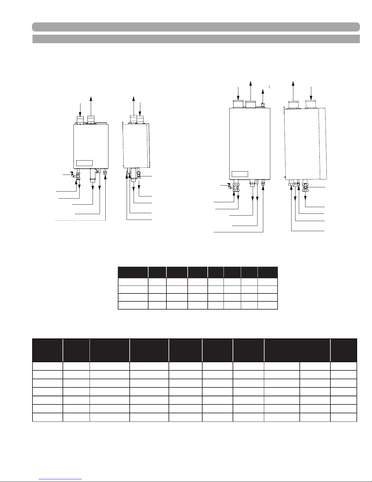
C. EVO DIMENSIONS
Condensate Trap
Cleaning Point
Gas (D)
Gas (D)
Inlet (B)
Inlet (B)
Air In (A)
Air In (A)
Left View
Outlet (C)
Outlet (C)
Exhaust
Out (A)
Exhaust
Out (A)
Relief Valve
Relief Valve
Condensate Waste
Condensate Trap
Cleaning Point
Front View
Air Vent
Air In (A)
Exhaust
Out (A)
Front View
Condensate Trap
Gas (D)
Inlet (B)
Outlet (C)
Relief Valve
Condensate Waste
Condensate Trap
Cleaning Point
Gas (D)
Inlet (B)
Air In (A)
Left View
Outlet (C)
Exhaust
Out (A)
Relief Valve
GENERAL INFORMATION
Cleaning Point
(TABLE 1-1) EVO DIMENSIONS
Model Width Heightt Depth A B C D
79–199.1 16" 20.5" 12" 3" 1" 1" 0.75"
299 19" 33" 19" 4" 1.5" 1.5" 0.75"
399 19" 33" 19" 4" 2" 2" 0.75"
599 19" 35" 26.5" 5" 2" 2" 1"
(TABLE 1-2) EVO INFORMATION
Water Heater*
Output
BTU/hr
Model
Input
BTU/hr
HW 129 136,000 up to 132,890 up to 130,150 160 199.1 265 [email protected]' [email protected]' 66 lbs
HW 199.1 199,999 up to 193,999 up to 189,999 233 291 388 [email protected]' [email protected]' 75 lbs
HW 299 300,000 up to 291,000 up to 285,000 360 450 600 [email protected]' [email protected]' 172 lbs
HW 399 399,999 up to 387,999 up to 379,999 466 582 776 [email protected]' [email protected]' 204 lbs
HW 599 630,000 up to 611,100 up to 598,500 734 917 1223 [email protected]' [email protected]' 260 lbs
*At 97% thermal efciency with 86oF incoming water to heat exchanger
**At 95% thermal efciency with 140oF incoming water to heat exchanger
Boiler**
Output
BTU/hr
GPH
Recovery
@ 100˚F∆T
GPH
Recovery
@ 80˚F∆T
GPH
Recovery
@ 60˚F∆T
Water Flow Rate &
Pressure Drop
DWH† Heating
Shipping
Weight
34000 Autry Street, Livonia, MI 48150 | 800.968.5530 | Fax 734.419.0209 | www.hamiltonengineering.com | LIT91127US REV 5/2018
Page 9
Page 10
GENERAL INFORMATION
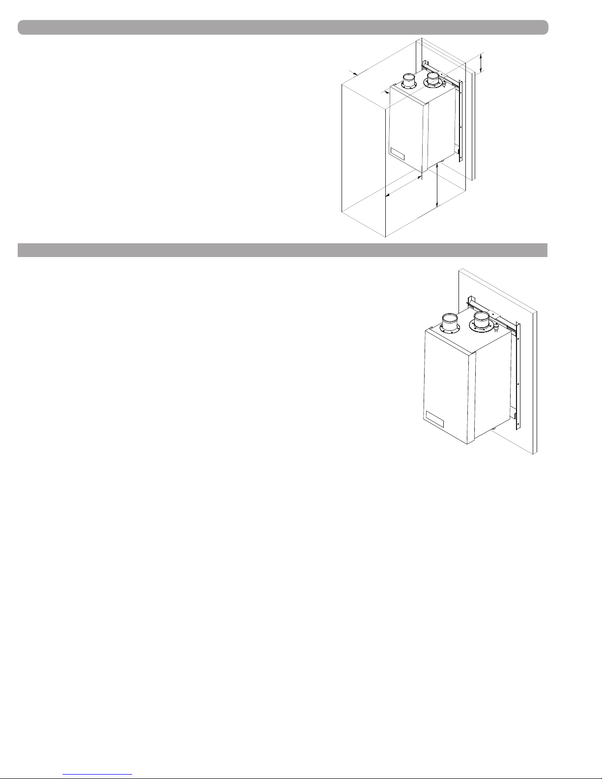
RECOMMENDED SERVICE CLEARANCES
3" Clearance
from side of unit
(FIGURE 1-2) EVO CLEARANCES
(NOTE: The EVO is rated at zero
clearance to combustibles.)
24" Clearance
from front of unit
D. PRE INSTALLATION REQUIREMENTS
The EVO models 299–599 are designed to be installed using a factory designed
and supplied rack or frame (see Figure 1-3 for details). Models 79–199.1 may also
be installed using an optional wall bracket. If the wall bracket is used, care must
be exercised to insure that the wall structure is sufcient to support the
weight of the connected load (see weights in Table 1-2, pg.9). Consult factory
for details of wall mount bracket. It can be installed in alcoves, basements, and
utility rooms, as well as standard equipment rooms. Choose a location for your
EVO, centralized to the piping system, along with consideration for Electrical
(Part 2, Gas Connection (Part 3), Venting (Part 4), and Condensate Drain (Part
4, Section F).
12" Clearance
from top of unit
18" Clearance
from bottom of unit
Zero Clearance
from back of unit
to wall
The EVO heat exchanger must be level as installed, and the mounting surface
must be designed to support the weight (see previous page, Table 1-2 for
weights). Be sure the appliance is adequately secured to the mounting surface.
(FIGURE 1-3)
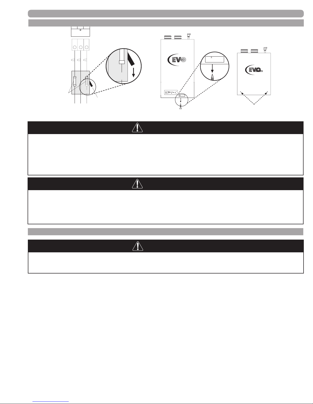
The front cover is secured by a threaded screw and two clasp style latches; it
EVO MOUNTING DETAIL
can only be installed one way. When removing the front cover of the EVO
unit, you must make sure all electric power to the appliance is turned off. Then remove the screw at the
bottom of the panel, undo the latches and remove the cover (see Figure 1-4 on the next page).
If the EVO is set up for liqueed petroleum (LP) gas, some geographic areas follow the Uniform Mechanical
Code, section 304.6, “Liqueed petroleum gas burning appliances shall not be installed in a pit, basement or
similar location where heavier-than-air gas might collect. Appliances so fueled shall not be installed in a below
grade under-oor space or basement unless such location is provided with an approved means for removal
of unburned gas.”
Note: A water chemistry analysis should be performed prior to any installation. If the water quality
exceeds any of the following levels, then a water chemistry analysis must be performed:
• Water hardness can be no more than 12 grains (205 ppm or mg/l)
• TDS (total dissolved solids) can be no more than 450 ppm or mg/l
• PH - below 6.5 or above 7.5
For total combined hardness over 15 grains (250 ppm or mg/l) or longer pipe lengths, contact Hamilton
Engineering for correct pump sizing. Combined, the hardness and TDS can be no more than 450 ppm.
Our internal term for this is the TCH (Total Combined Hardness).
34000 Autry Street, Livonia, MI 48150 | 800.968.5530 | Fax 734.419.0209 | www.hamiltonengineering.com | LIT91127US REV 5/2018
Page 10
Page 11
GENERAL INFORMATION
F
OFF
D. PRE INSTALLATION REQUIREMENTS CONT.
use
15
14
L L
Power supply
230 VAC
ST-7
16
#1 Turn off power
to unit
ON
OFFOFF
To Ground
Service Switch
#2 Remove bottom
screw(s)
WARNING!
Before removing screw and opening front cover,
main power supply must be disconnected (shut off).
INNOVATIVE CONDENSING TECHNOLOGY
By Hamilton Engineering, Inc.
ON
TEMPERATURE
RESET
SERVICE
-+
CH
LO
OFF
WARNING!
HIGH VOLTAGE - RISK OF ELECTRICAL SHOCK!
INNOVATIVE CONDENSING TECHNOLOGY
By Hamilton Engineering, Inc.
(FIGURE 1-4) HOW TO REMOVE THE FRONT COVER
The EVO is certied as an indoor appliance. Do not install the EVO outdoors
or location where it will be exposed to freezing temperatures. This includes
all related piping and components. If the EVO is subjected to ood water or
submersed in water, the EVO must be replaced.
NOTICE
Condensation Removal: This is a condensing, high efciency appliance, therefore condensation removal must be addressed to avoid damage to surrounding
area or appliance. See Part 4, Section F for Condensate Requirements (pg.28).
E. PRESSURE RELIEF VALVE
WARNING
Do not, under any circumstances, thread a cap or plug into the relief valve!
Explosion, severe personal injury, death, or major property damage may result.
This unit is supplied with a relief valve sized in accordance with ANSI/ASME Heater and Pressure Vessel Code,
Section IV. The relief valve is installed near the hot water outlet. If the valve supplied is replaced, the pressure
rating of the valve must not exceed the listed working pressure of this appliance, and must be rated to the proper
BTU/hr capacity of the water heater. Do not, under any circumstances, thread a cap or plug into the relief
valve! Explosion, serious injury or death may result! To prevent water damage, the relief valve piping must
be directed to the oor or an open drain, but not connected directly. There must be a 6” space between the outlet
of relief valve piping and drain or oor. Do not hook up to drain system directly without an air gap. Protect from
freezing. Place no other valve between the relief valve and the unit. Do not install any reducing couplings or other
restrictions in the discharge line. The discharge line must allow complete drainage of the valve and line. Manually
operate the relief valve at least once a year.
Also, care must be exercised when choosing the location of this appliance, where leakage from the relief
valve, leakage from related piping, or leakage from the tank or connections, will not result in damage to the
surrounding areas, or to the lower oors of the building. A water heating appliance should always be located in an
area with a oor drain or installed in a drain pan suitable for water heating appliances. Under no circumstances,
shall Hamilton Engineering, Inc. be held liable for any such water damage whatsoever.
34000 Autry Street, Livonia, MI 48150 | 800.968.5530 | Fax 734.419.0209 | www.hamiltonengineering.com | LIT91127US REV 5/2018
Page 11
Page 12
ELECTRICAL
PART 2. ELECTRICAL
A. ELECTRICAL CONNECTION / REQUIREMENTS
The electrical connection for the EVO is on the bottom of the unit. There is a 1/2" knockout location for an electrical connection for
the heater’s incoming power connection. All electrical wiring must be performed by a qualied licensed electrician in accordance
with National Electrical Code ANSI/NFPA and/or the Canadian Electrical Code, Part 1 CSA C22.1, or to any applicable local
codes and standards. For your convenience, all the points for electrical connections needed to operate the EVO are labeled.
Note: Always check electrical ground to known earth ground; if less than 0.5 ohms, ground is sufcient (meter MUST
be on lowest setting).
We recommend a simplied test, differing from one looking for building earth ground issues, it is our intent to use this test as
an indicator of equipment room (boiler or water heater) electrical grounding issues, or equipment bonding issues, not prove
the earth ground to the building.
Take an Ohm meter and place one lead on a known earth ground (not the ground wire on the boiler), and place the other
lead on either 1) The near boiler system piping, 2) The boiler heat exchanger, or 3) The boiler cabinet.
If any of those readings exceed 0.5 Ohms, then it is a good indicator that there may be sufcient stray current owing
through the water in the piping system to accelerate or amplify conditions that can cause pump, boiler or piping issues in
the not too distant future.
If any readings are over 0.5 ohms, an electrician should be brought in to correct the problem.
The electrical requirements are for standard 208–240 volts, 50/60 Hz 15 Amp service. This unit is wired with #18 awg and
internally fused for no more than 3.15 Amps. When the unit is rst powered on, there is a self-setting of the electronics for 50
Hz or 60 Hz. At every power up, the electronics will take a couple of seconds to compare the pulses of the power to the pulses
of the crystal, which is built into the electronics. Then all time-related functions are correct no matter the power source.
The standard supplied pumps are all 208–240 VAC, 60 cycle and are to be wired to terminals indicated on the appliance. In
50 cycle applications, other pumps may need to be supplied, depending on water conditions. With the 914 controller there
is an ability to program a custom pump delay time, or to use a continuous (no time out) setting. The factory default is a 1
minute delay to turn off after completing a burn cycle.
B. INTERNAL WIRING CONNECTION
CAUTION
The incoming power shall be connected directly to the labeled, intended
connection points only. Failure to do so may result in an electrical short and
the control board will have to be replaced!
DANGER
IT IS EXTREMELY IMPORTANT THAT THIS UNIT BE PROPERLY GROUNDED!
IT IS VERY IMPORTANT THAT THE BUILDING GROUND IS INSPECTED BY A
QUALIFIED ELECTRICIAN PRIOR TO MAKING THIS CONNECTION!
Failure to conrm proper grounding and the absence of stray voltage may result in premature component failure.
See start up and commissioning documents (LIT91111 - Start Up Checklist) for details.
Terminal 27 in the electrical compartment must be connected to the building ground system.
The incoming 208–240 volt single phase power supply is connected to terminals 26 through 28.
It is important that the electrical power is not turned on at this time. Double check all connections and then turn the
power on. The display that is provided with the EVO should now be reading the Setpoint temperature.
Note: See Start-Up Procedures (Part 6, page 38) to change the temperature setting or run the appliance.
34000 Autry Street, Livonia, MI 48150 | 800.968.5530 | Fax 734.419.0209 | www.hamiltonengineering.com | LIT91127US REV 5/2018
Page 12
Page 13
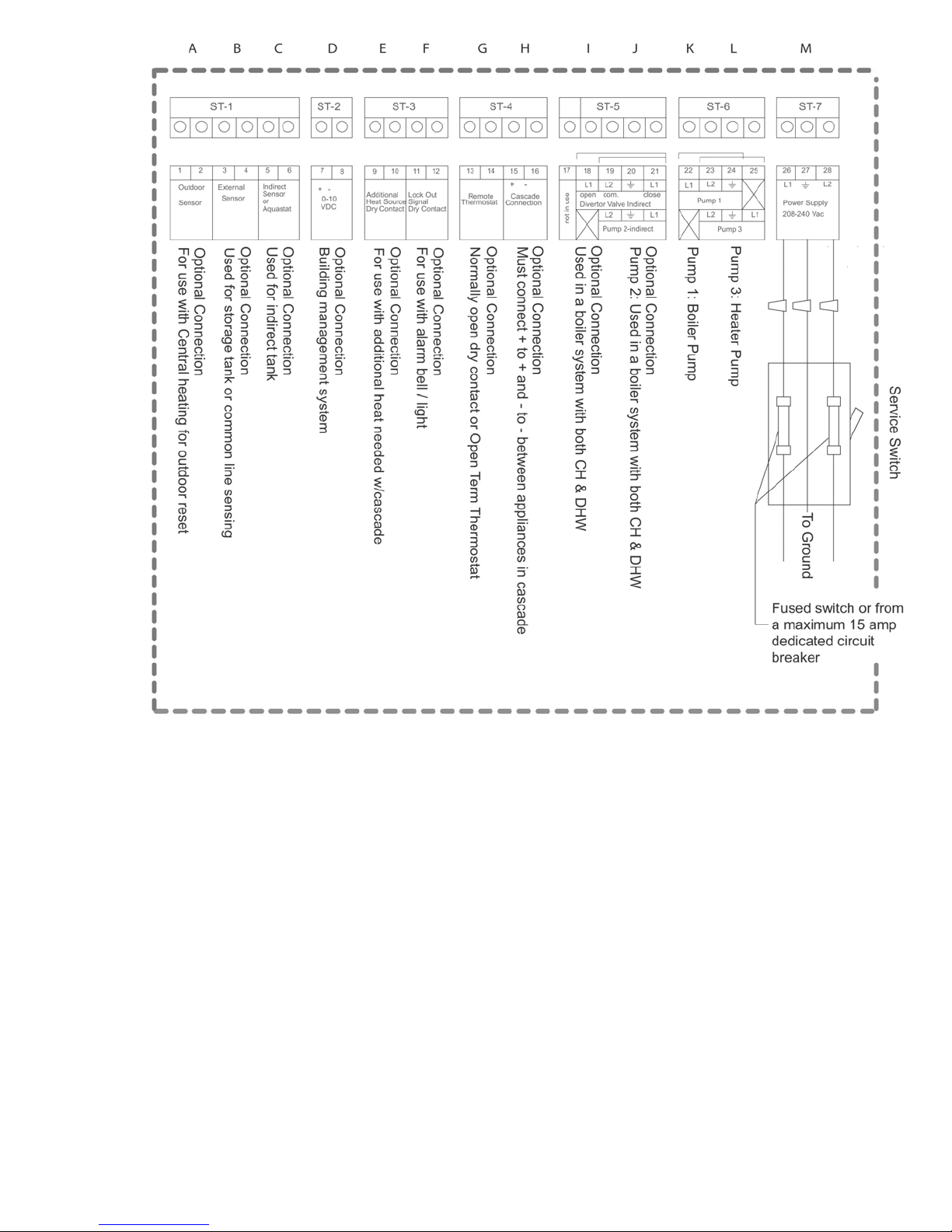
(FIGURE 2-1) FIELD WIRING CONNECTIONS
A. Outdoor Sensor - outdoor air sensor, set point will adjust based on outdoor air temperature (not
needed if 0-10 VDC output is connected)
B. External sensor connection - system temperature sensor, senses water temp in a storage tank or
a heating loop.
C. Indirect Tank Sensor - Sensor for indirect DHW. An aquastat may also be connected here.
D. 0–10 VDC - connect a 0–10 VDC output here to vary set point temperature.
E. Additional Heat Source - dry contacts that will close a thermostat on an extra heater/boiler if the
cascade system is at 100% of capacity.
F. Lock Out Signal - alarm bell or light may be connected here to indicate that the boiler is a hard lockout.
G. Remote Thermostat - normally jumped. A room thermostat may be connected here to enable/
disable the heater/boiler.
H. Cascade Connection - communication cables get connected here and “daisy chained” to all heaters/
boilers in a cascade. This is polarity sensitive.
I. 3-Way Diverter Valve - Used in a boiler system with both Heating and Indirect Hot Water.
J. P2 - Pump for indirect. Used in a boiler system with both Heating and Indirect Hot Water.
K. P1 - Wire to primary pump for boilers.
L. P3 - Wire to primary pump for heaters or system pump for boilers.
M. Power Supply - connect 208–240 VAC single phase power supply here.
34000 Autry Street, Livonia, MI 48150 | 800.968.5530 | Fax 734.419.0209 | www.hamiltonengineering.com | LIT91127US REV 5/2018
Page 13
Page 14
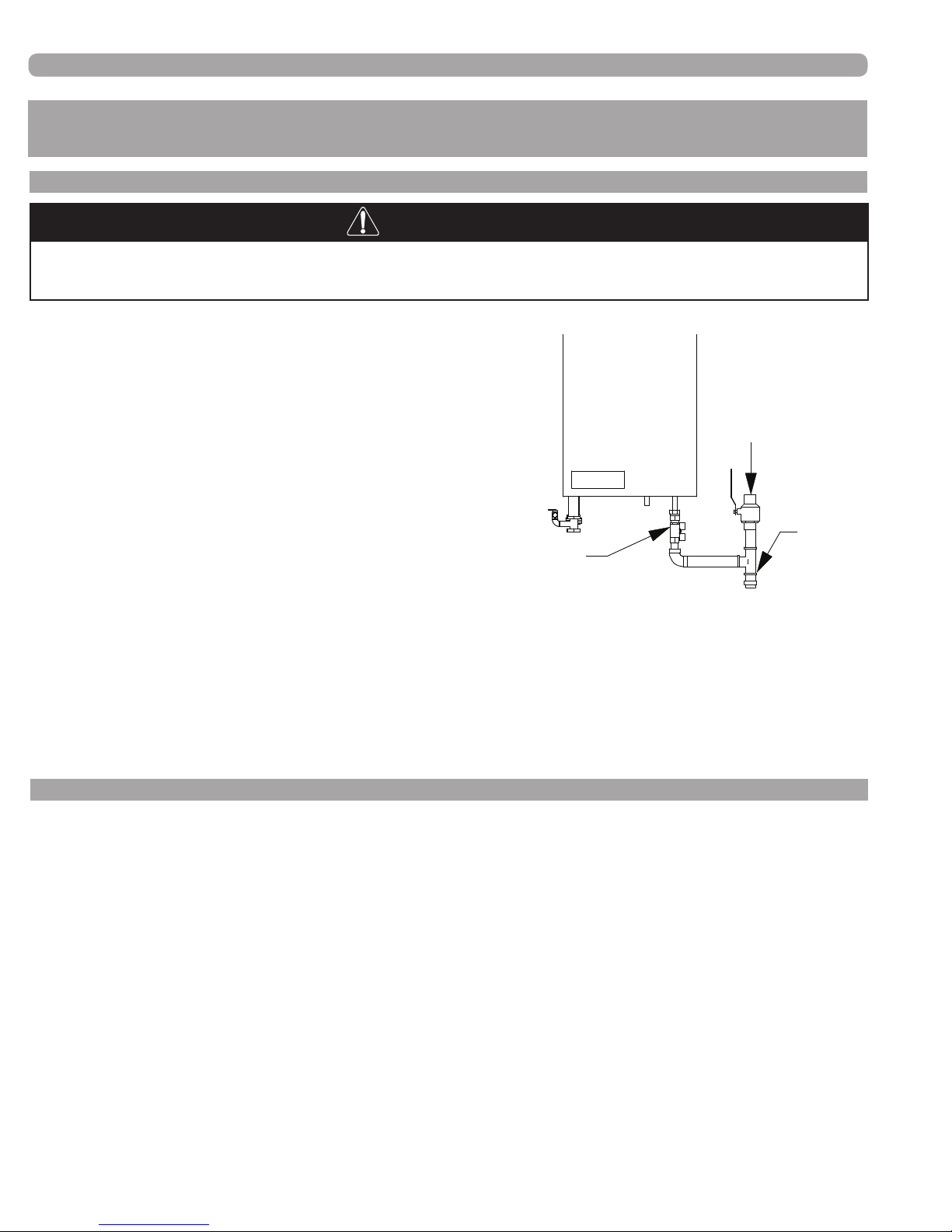
GAS CONNECTION
PART 3. GAS CONNECTION
A. GAS CONNECTION
Failure to follow all precautions could result in re, explosion or death!
The gas supply shall have a maximum inlet pressure of less
than 14" water column (1/2 PSI) (3.44 kPa), and a minimum
of 4" water column. The entire piping system, gas meter and
regulator must be sized properly to prevent pressure drop
greater than 1" as stated in the National Fuel Gas Code. This
information is listed on the rating plate. It is very important
that you are connected to the type of gas as noted on
the rating plate, “LP” for liqueed petroleum, propane gas
or “Nat” for natural or city gas. All gas connections must be
approved by the local gas supplier, or utility in addition to the
governing authority, prior to turning the gas supply on. It is
mandatory that a drip leg be fabricated, as per the National Fuel Gas code. Once all the inspections have been performed, the piping must be leak tested. It is recommended
that a soapy solution be used to detect leaks. Bubbles will
appear on the pipe to indicate a leak is present. If the leak test
requirement is a higher test pressure than the maximum inlet
pressure, you must isolate the EVO from the gas line. In order to do this, you must shut the gas off using factory
and eld-installed gas cocks (following the lighting instructions in Part 6, Section B, Page 38.) This will prevent
high pressure from reaching the valve. Failure to do so may damage the gas valve. In the event the gas valve is
exposed to a pressure greater than 14" water column, the gas valve must be replaced.
Never use an open ame (match, lighter, etc.) to check gas connections.
Gas
Shut-off
Valve
(FIGURE 3-1) EVO GAS CONNECTION
Gas
Supply
Drip
Leg
B. GAS PIPING
The gas piping must be sized for the proper ow and length of pipe, to avoid pressure drop. Both the gas meter
and the gas regulator must be properly sized for the total gas load. If you experience a pressure drop greater than
1" WC, the meter, regulator or gas line is undersized or in need of service. You can attach a manometer to port
3 of the gas valve (see Figures 3-2 and 3-3 on the following page). Alternatively, you can attach the manometer
to the incoming gas drip leg, by removing the cap and installing the manometer. The gas pressure must remain
between 4" and 14" during stand-by (static) mode and while in operating (dynamic) mode. If an in-line regulator
is used, it must be a minimum of 10 equivalent feet from the EVO. It is very important that the gas line is
properly purged by the gas supplier or utility. Failure to properly purge the lines or improper line sizing,
will result in ignition failure. This problem is especially noticeable in NEW LP installations and also in empty
tank situations. This can also occur when a utility company shuts off service to an area to provide maintenance
to their lines. This gas valve must not be replaced with a conventional gas valve under any circumstances. As an
additional safety feature, this gas valve is easily de-coupled from the fan inlet.
Refer to the following tables to size the supply piping to minimize pressure drop between meter or
regulator and unit.
34000 Autry Street, Livonia, MI 48150 | 800.968.5530 | Fax 734.419.0209 | www.hamiltonengineering.com | LIT91127US REV 5/2018
Page 14
Page 15
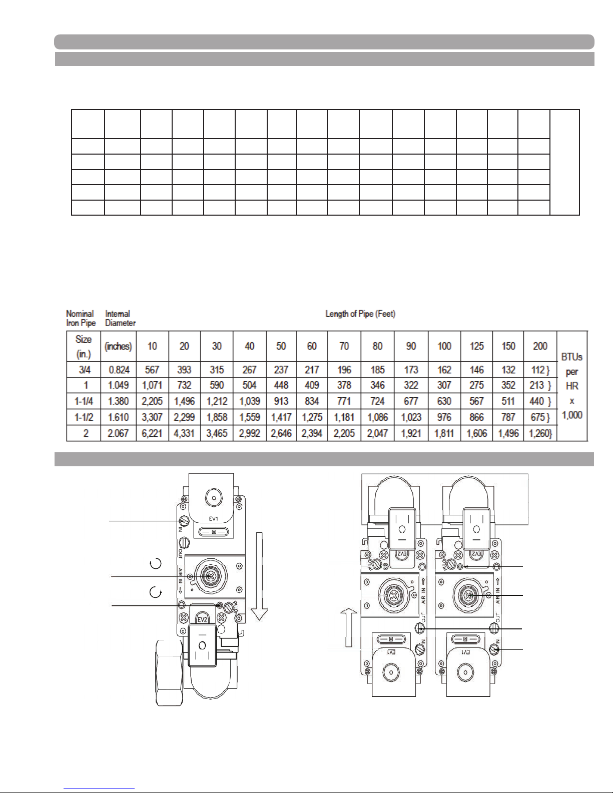
DO NOT ADJUST
GAS CONNECTION
C. GAS TABLES
(TABLE 3-1) NATURAL GAS SUPPLY PIPING
Nominal Internal Length of Pipe (Feet)
Iron Pipe Diameter
Size
(inches) 10 20 30 40 50 60 70 80 90 100 125 150 200
(in.)
3/4 0.824 363 249 200 171 152 138 127 118 111 104 93 84 72 }
1 1.049 684 470 377 323 286 259 239 222 208 197 174 158 135 }
1-1/4 1.380 1,404 965 775 663 588 532 490 456 428 404 358 324 278 }
1-1/2 1.610 2,103 1,445 1,161 993 880 798 734 683 641 605 536 486 419 }
2 2.067 4,050 2,784 2,235 1,913 1,696 1,536 1,413 1,315 1,234 1,165 1,033 936 801 }
(Based on 0.60 specic gravity for natural gas at 0.5" WC pressure drop; DOE standard is 1100 BTU per
cubic foot of natural gas.)
1 Run the gas supply line in accordance with all applicable codes.
2. Locate and install manual shut off valves in accordance with state and local requirements.
(TABLE 3-2) PROPANE SUPPLY PIPING (Based on 11" WC supply pressure)
BTUs
per
HR
x
1,000
D. GAS VALVE SETUP
3
2
1
(FIGURE 3-2) EVO MODELS 79–399 (FIGURE 3-3) EVO MODEL 599
increase
increase
1
2
(DO NOT TOUCH LEFT
4
HAND GAS VALVE!)
3
34000 Autry Street, Livonia, MI 48150 | 800.968.5530 | Fax 734.419.0209 | www.hamiltonengineering.com | LIT91127US REV 5/2018
Page 15
Page 16
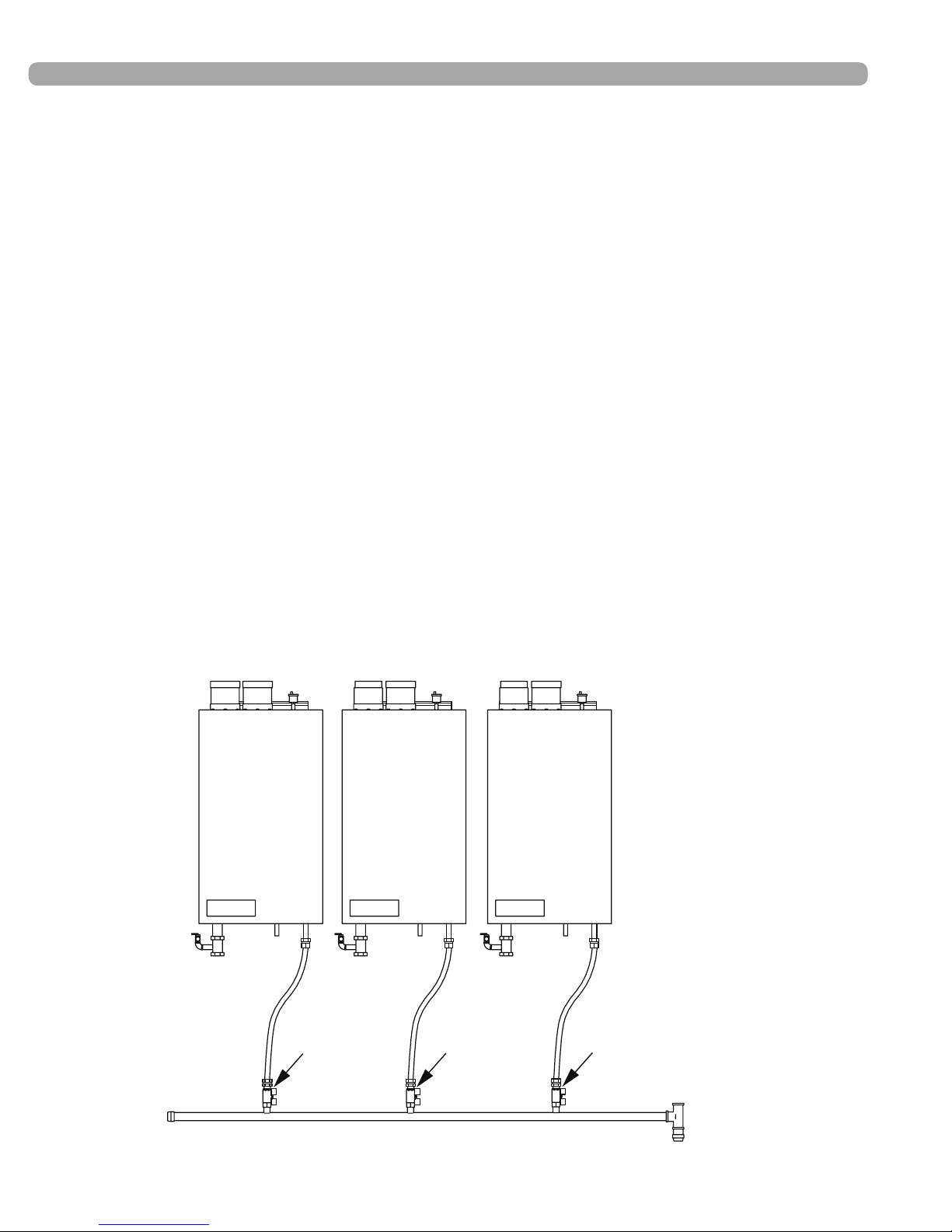
Gas Pressure
Test Point
Gas Pressure
Test Point
Gas Pressure
Test Point
GAS CONNECTION
Please see Part 6 - Start-Up Procedures on page 38 before continuing!
Proper gas volume and pressure is critical to the operation of any high efciency appliance. There are three
types of measurements that must be taken to provide the data to insure product performance:
• Lock-up pressure (pressure in gas piping at appliance inlet with no load) may not exceed 14" wc.
at any time!
• Minimum load at ignition of a single unit in a multiple unit rack
• Maximum load – all appliances on at full re that are being tested and any other gas red
equipment on the same gas supply.
How and where to measure:
• All gas pressure tests must be taken at the gas manifold inlet, external to the EVO (see diagram).
• Gas pressure for minimum load should be measured the moment after the gas valve opens on
a single EVO, and recorded.
• Gas pressure for maximum load shall be measured with all units on at full re and all other
connected loads on that gas supply running
• Gas pressure drop shall not exceed 1" wc. between minimum load and maximum load
as described above.
(FIGURE 3-4) GAS PRESSURE TESTING POINTS
34000 Autry Street, Livonia, MI 48150 | 800.968.5530 | Fax 734.419.0209 | www.hamiltonengineering.com | LIT91127US REV 5/2018
Page 16
Page 17
GAS CONNECTION
(TABLE 3-3) COMBUSTION & FUEL RELATED ADJUSTMENT TABLE
Natural Gas CO
Cover On Cover Off
Natural Gas CO ppm LP Gas CO
2
Approximate, do not use for setup!
Cover On Cover Off
2
LP Gas CO ppm
Approximate, do not use for setup!
LOW FIRE 8.5% 8.3% Less than 10 9.6% 9.4% Less than 15
HIGH FIRE 8.8% 8.6% Less than 110 10.0% 9.8% Less than 120
Please note: All adjustments must be made with the appliance door off, which will lower the CO
reading
2
0.2%. See tables above for specic readings.
When checking or replacing a gas valve, the CO
percentage in the ue gas is the preferred measuring method
2
to insure proper combustion and ring rate. CO is used as the (temporary) alternate.
Changing incoming air temperature may vary the CO
setting slightly (~0.2–0.6%) after initial set up. This is not
2
cause for concern or reason to set up again. After one year of operation, set up is required again.
If your appliance will be operated in an area that has inlet air temperature variations greater than 80ºF, please
use the following table in adjusting your CO
for optimum performance.
2
(TABLE 3-4) CO2 ADJUSTMENT TABLE
Inlet air ∆T variation
80ºF Reduce CO
100ºF Reduce CO
120ºF Reduce CO
Setup at minimum incoming
air temperature
0.2% Increase CO2 0.2%
2
0.3% Increase CO2 0.3%
2
0.4% Increase CO2 0.4%
2
Setup at maximum incoming
air temperature
E. SETTING THE MAXIMUM LOAD
A means of sampling the leaving ue gas is built into the vent connector on top of the appliance. Remove the
rubber plug for testing and replace when testing is completed. This plug MUST be in place during normal operation.
• Press the service button with a pointed object and set the temperature knob on the maximum fan speed as
shown by model in the table below (RPM = display * 100, ex. 060 = 5951–6050).
If necessary, turn the adjusting slot [1], which sets the high re performance, either counterclockwise to increase
the CO2 percentage or clockwise to reduce the CO2 percentage, as shown in Figures 3-2 and 3-3, page 15.
Appropriate CO2 percentages are shown in Table 3-3 above.
(TABLE 3-5) FAN SPEED REQUIREMENTS
Last 4 digits of serial number
HWD 79, HWH 79, HWH 79.8
First Week Last Week Maximum rpm Minimum rpm
02--08 current 6400 1856
34000 Autry Street, Livonia, MI 48150 | 800.968.5530 | Fax 734.419.0209 | www.hamiltonengineering.com | LIT91127US REV 5/2018
Page 17
Page 18
GAS CONNECTION
Last 4 digits of serial number
HWD 129, HWH 129, HWH 129.8
First Week Last Week Maximum rpm Minimum rpm
49-06 07-14 5900 1947
52-14 current 6000 1740
Last 7 digits of serial number HWD 179, HWH 179, HWH 179.8
First Week Last Week Maximum rpm^ Minimum rpm
009-43-07 023-48-07 5800 1856
009-43-07 008-48-07 5600 1680
024-11-08 current 5600 1736
Last 4 digits of serial number
HWD 199, HWD 199.1, HWH 199, HWH 199.1, HWH 199.8
First Week Last Week Maximum rpm Minimum rpm
49--06 current 6500 1755
Last 4 digits of serial number
HWD 299
First Week Last Week Maximum rpm Minimum rpm
02--08 current 6300 1575
Last 4 digits of serial number
HWD 399
First Week Last Week Maximum rpm Minimum rpm
24--05 current 6200 1798
Last 4 digits of serial number HWD 599
First Week Last Week Maximum rpm Minimum rpm
24--05 current 5700 1596
Do not forget to place the knob, labeled with “Setpoint,” at the proper temperature value when done.
F. SETTING THE MINIMUM LOAD
Set the minimum load once the maximum load has been set, turn the knob until the minimum RPM setting
has been reached. In order to set or adjust the minimum load, turn the screw [2] for the minimum setting (rst
remove the protective cap). Turn the screw clockwise to increase or counter clockwise to decrease the CO
2
percentage. On the HW 599, you only are allowed to set the gas valve at the right side; the left gas valve is set by
the manufacturer. See Section H, page 19 for special instructions on replacing both gas valves in a model 599.
• If the measuring process takes more than 40 minutes, the appliance will return to the automatic mode.
If so required, press the Service button another time.
• When you are done setting the valve, press the Service button again to return to normal run mode
Please do not forget to replace the protective cap on the gas valve!
34000 Autry Street, Livonia, MI 48150 | 800.968.5530 | Fax 734.419.0209 | www.hamiltonengineering.com | LIT91127US REV 5/2018
Page 18
Page 19
GAS CONNECTION
G. GAS CONVERSION
If the appliance is to be converted in the eld for using Propane (LPG), the following steps must be taken:
• Turn screw [1] clockwise (Figure 3-2, page 15) ¾ of a full turn (270°) on models HW 79/199.1,
¾ of one turn (270°) on models HW 199.1/299 and 1 full turn (360°) on model HW399
• On model HW599 (Figure 3-3, page 15) turn screw on left hand valve closed (clockwise) and turn right
valve 1-¾ of a full turn clockwise.
• Run the appliance. If the burner does not ignite after four starting efforts, turn the screw [1] one half turn
back (180°) (counter clockwise).
• After conversion, follow the steps in Sections E and F for setting the maximum and minimum loads,
using the LP gas values shown in Table 3-3, page 17.
H. GAS VALVE MAINTENANCE/REPLACEMENT
1) When checking or replacing a gas valve, the CO
percentage in the ue gas is the preferred
2
measuring method to insure proper combustion and ring rate. CO is used as the alternate.
2) Gas valve replacement for the HW 599:
The left hand gas valve (which is normally factory-set and sealed and must not be adjusted) must be set up to
factory specications before any combustion related adjustments can be performed on the right hand valve. An
electronic manometer must be used, as it will be set to a scale of 0.01" WC.
The adjustment screw [1] (see Figure 3-3, page 15) normally used for setting maximum ow rate must be turned
counterclockwise until it begins to click when turned. The screw will not fall out, but will be fully retracted at this
point. this is for Natural Gas, for LP gas, close the left hand valve (clockwise) until it is closed down.
The digital manometer must now be connected to the outlet pressure tapping [4] on the left hand valve only
(marked do not adjust in Figure 3-3 page 15), and the appliance red. It must be placed in the service mode
and held at the minimum ring rate (1653 rpm fan speed). With the appliance ring at this rate, adjust the offset
(minimum ring rate) screw [2] to a pressure of “0” +/- .0.01" WC. Be sure the manometer has been zeroed
out prior to making this setting.
Once this operation is complete, you may follow the instructions for setting the minimum and maximum ring rate
as shown in Sections G and H, for the right hand gas valve only.
WARNING
Failure to follow all precautions could result in re, explosion, or death!
It is extremely important to follow these venting instructions carefully. Failure to
do so can cause severe personal injury, death or substantial property damage.
34000 Autry Street, Livonia, MI 48150 | 800.968.5530 | Fax 734.419.0209 | www.hamiltonengineering.com | LIT91127US REV 5/2018
DANGER
Page 19
Page 20
PART 4. VENTING
A. APPROVED VENTING MATERIALS
All vent pipe materials and ttings must comply with the following:
Item Material
AL 29-4C Stainless ANSI/ASTM UL1738 UL1738
Vent pipe
and
ttings
PVC schedule 40* ANSI/ASTM D1785 CPVC and PVC venting must be ULC-
CPVC schedule 40 ANSI/ASTM F441
Polypropylene ULC-S636 ULC-S636
VENTING
Standards for installation in:
United States Canada
S636 Certied. IPEX is an approved vent
manufacturer in Canada supplying vent
material listed to ULC-S636.
Pipe cement
& primer
Please note: Venting system may contain one or more of the above materials.
The EVO is a direct vent appliance. The EVO is listed as a Category IV. Condensing Appliance.
PVC ANSI/ASTM D2564
CPVC ANSI/ASTM F493
NOTICE: DO NOT USE CELLULAR (FOAM) CORE PIPE
(The EVO Venting is rated at Zero Clearance to combustibles.)
IPEX System 636
Cements & Primers
SPECIAL VENTING SYSTEM DESIGN NOTES
The EVO efciency testing and ratings are based on a sealed, two pipe vent
system; however, many other vent congurations are available as factory
engineered solutions. Please contact the factory if exceptions are required for
your installation.
DANGER
It is extremely important to follow these venting instructions carefully. Failure to
do so can cause severe personal injury, death or substantial property damage.
WARNING
This vent system will operate with a positive pressure in the vent pipe. Do not
connect vent connectors serving appliances by natural draft into any portion of
mechanical draft systems operating under pressure.
Note: For concrete construction or to meet certain re codes, exhaust and inlet piping at the wall penetration to
the EVO must be CPVC Schedule 40 or 80 or stainless. The balance from the penetrated wall to the outside may
be PVC Schedule 40 or 80.
Note: If return water temps exceed 130ºF, use of PVC is NOT recommended, even though product is
approved as such. Contact Hamilton Engineering at 800.968.5530 for further clarication.
34000 Autry Street, Livonia, MI 48150 | 800.968.5530 | Fax 734.419.0209 | www.hamiltonengineering.com | LIT91127US REV 5/2018
Page 20
Page 21
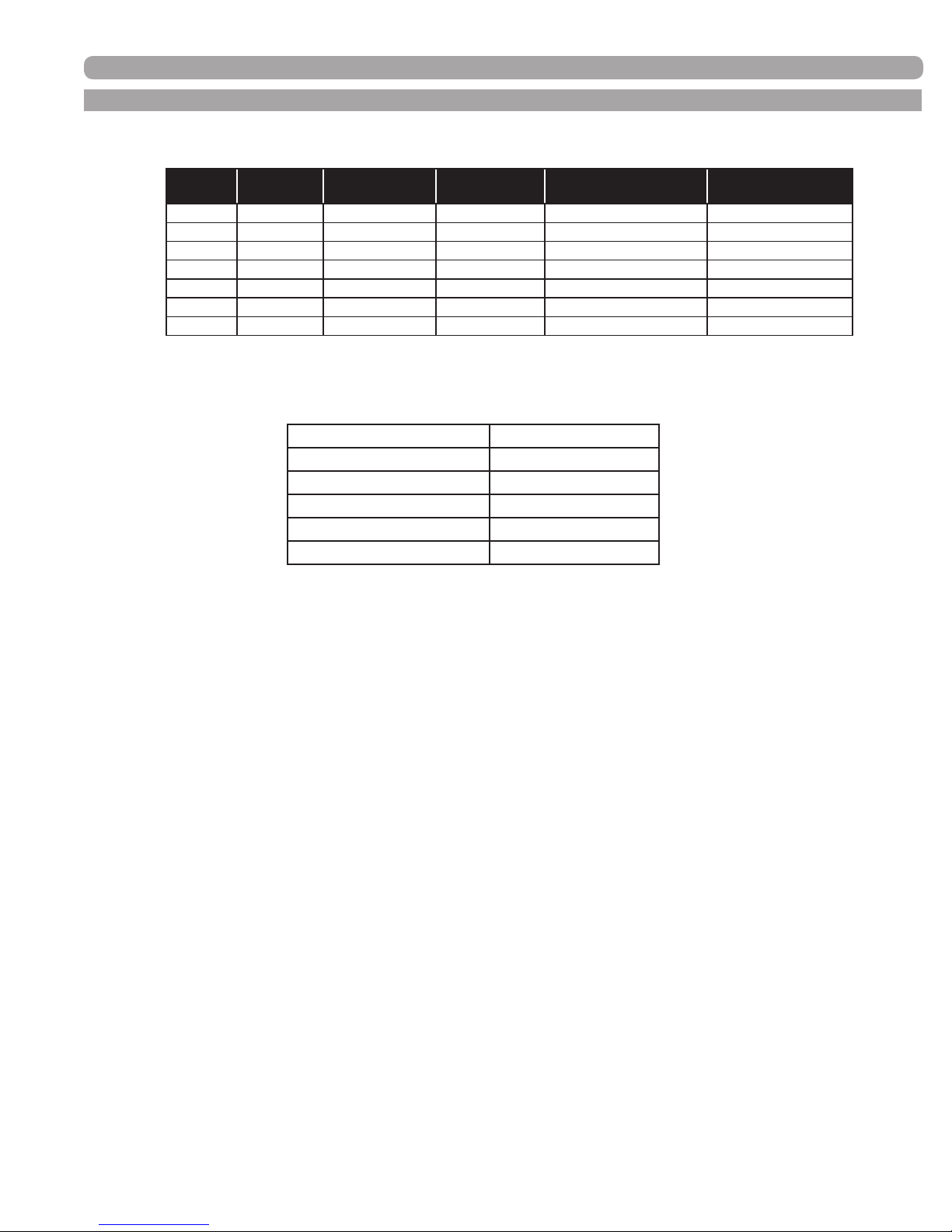
B. VENTING THE EVO
(TABLE 4-1) VENTING SPECIFICATIONS
VENTING
Model
HW 79 3" Plastic Stainless 6' + (2) 90º elbows 250'
HW 129 3" Plastic Stainless 6' + (2) 90º elbows 200'
HW 179 3" Plastic Stainless 6' + (2) 90º elbows 160'
HW 199.1 3" Plastic Stainless 6' + (2) 90º elbows 90'
HW 299 4" Plastic Stainless 6' + (2) 90º elbows 225'
HW 399 4" Plastic Stainless 6' + (2) 90º elbows 180'
HW 599 5" Stainless Plastic - 6"
Vent
Diameter
Standard Vent
Type
Optional Vent
Type
*
Minimum Combined
Vent Length
6' + (2) 90º elbows 200'
*The use of 6" PVC will require the purchase of a
special adapter from Hamilton Engineering, Inc.
Maximum Combined
Length
(TABLE 4-2) EQUIVALENT FEET
Fittings or Piping Equivalent Feet
90 degree elbow 5'
45 degree elbow 3'
Coupling 0
Air inlet elbow 6'
Exhaust coupling 1'
The inlet and exhaust pipes on the top of the cabinet should be the diameter and material indicated in the Venting
Specications Table above. It is very important that you plan the location properly to eliminate long pipe runs and
excessive ttings. Inlet pipe size must not be reduced. Do not combine the inlet air or exhaust with any other inlet
or exhaust pipe including either to an additional similar appliance, unless you have purchased an engineered
Common Venting System from Hamilton Engineering, Inc. The joints must be properly cleaned, primed and
cemented if plastic, and sealed per the manufacturer’s instructions if stainless. The piping must also be properly
supported as per Local and National Standard Plumbing Codes. It is important that the piping must be clean and
free from burrs, debris, ragged ends and particles of PVC (if applicable).
34000 Autry Street, Livonia, MI 48150 | 800.968.5530 | Fax 734.419.0209 | www.hamiltonengineering.com | LIT91127US REV 5/2018
Page 21
Page 22
VENTING
B. VENTING THE EVO CONT.
Exhaust piping should be sloped back to the connection on the EVO, at least 1/4” per foot to remove additional
condensate that forms within the pipe. The total combined length of pipe (intake piping plus exhaust piping added
together) including elbow allowances intake and exhaust should not exceed the length shown in the vent table.
The minimum combined vent length should not be less than a combined length of 6’ plus two 90° elbows. Choose
your vent termination locations carefully. You must also make certain that exhaust gas does not re-circulate back
into the intake pipe. You must place them in an open area and follow the following guidelines:
NOTICE
The following are code restrictions for the location of the ue gas vent terminal.
Compliance to these requirements doesn’t insure a satisfactory installation;
good common sense must also be applied. It is important to make sure that
exhaust gases are not recirculated into the inlet air of the EVO. If there is any
doubt, contact the factory BEFORE installing.
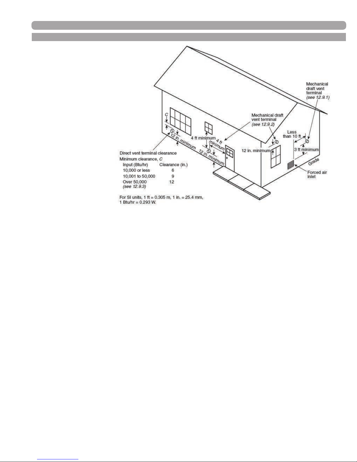
1) Never vent into a walkway, patio area, alley or otherwise public area less than 7' from the ground.
(See detail below references Fig. A.12.9 in the National Fuel Gas Code 2009 “Exit Terminals of
Mechanical Draft and Direct-Venting Systems;” see Figure 4-1, pg.23)
2) Never vent over or under a window or a doorway where the exhaust plume or condensation liquid will
cause obtrusive or dangerous conditions. (Refer to National Fuel Gas Code, CAN B149).
3) Never install a heat saver or similar product to capture waste heat from exhaust.
4) Always have a vent location at least 12" above maximum snow level.
5) Always have vent a minimum of 24" above ground level, away from shrubs and bushes.
6) Follow local gas codes in your region or refer to National Fuel Gas Code, Can B149.
7) Always have at least 36" distance from an inside corner of the outside walls.
8) Maintain at least 48" clearance to electric, gas meters, windows, exhaust fans, chimneys, inlets or
mechanical vents.
9) VERY IMPORTANT! The inlet air connection must be connected to outside air and should be located
no closer than 8" and no further than 24" to the exhaust.
Always place screens in all openings in intake and exhaust to prevent foreign matter from entering the EVO.
10)
11) The vent intake and exhaust must be properly cleaned and glued if plastic, and sealed per the
manufacturer’s directions if stainless for a pressure tight joint. Several methods for venting the EVO
can be found in Figures 4-2 through 4-6 of this section. Use these layouts as guidelines: certain
site conditions such as multiple roof lines/pitches may require venting modications (consult Hamilton
Engineering, Inc.).
34000 Autry Street, Livonia, MI 48150 | 800.968.5530 | Fax 734.419.0209 | www.hamiltonengineering.com | LIT91127US REV 5/2018
Page 22
Page 23
B. VENTING THE EVO CONT.
*IMPORTANT NOTE
HAMILTON ENGINEERING, INC.
RECOMMENDS A MINIMUM
CLEARANCE OF 4 FEET WHERE
THE EXHAUST PLUME CAUSED BY
THE UNIT MAY OBSTRUCT VIEWS
OR AFFECT THE COSMETIC LOOK
OF THE BUILDING. IN CANADA,
THERE IS A MINIMUM CLEARANCE
OF 10 FEET.
VENTING
* REFERENCE: THE NATIONAL FUEL GAS CODE 2009 EDITION
Through-the-Wall Vent Termination
1) A through-the-wall mechanical draft venting system shall terminate at least 3 ft (0.9 m) above any forced
air inlet located within 10 ft (3 m).
Exception No. 1: This provision shall not apply to the combustion air intake of a direct vent appliance.
Exception No. 2: This provision shall not apply to the separation of the integral outdoor air inlet and ue
gas discharge of listed outdoor appliances.
2) A through-the-wall mechanical draft venting system of other than direct vent type shall terminate at least
4 ft (1.2 m) below, 4 ft (1.2 m) horizontally from, or 1 ft (300 mm) above any door, operable window, or
gravity air inlet into any building. The bottom of the vent terminal shall be located at least 12 in. (300 mm)
above nished ground level.
3) The through-the-wall vent terminal of a direct vent appliance with an input of 10,000 Btu/hr (3 kW) or less
shall be located at least 6 in. (150 mm) from any air opening into a building, an appliance with an input
over 10,000 Btu/hr (3 kW) but not over 50,000 Btu/hr (14.7 kW) shall be installed with a 9 in. (230 mm)
vent termination clearance, and an appliance with an input over 50,000 Btu/hr (14.7 kW) shall have at
least a 12 in. (300 mm) vent termination clearance. The bottom of the vent terminal and the air intake
shall be located at least 12 in. (300 mm) above nished ground level.
34000 Autry Street, Livonia, MI 48150 | 800.968.5530 | Fax 734.419.0209 | www.hamiltonengineering.com | LIT91127US REV 5/2018
Page 23
Page 24
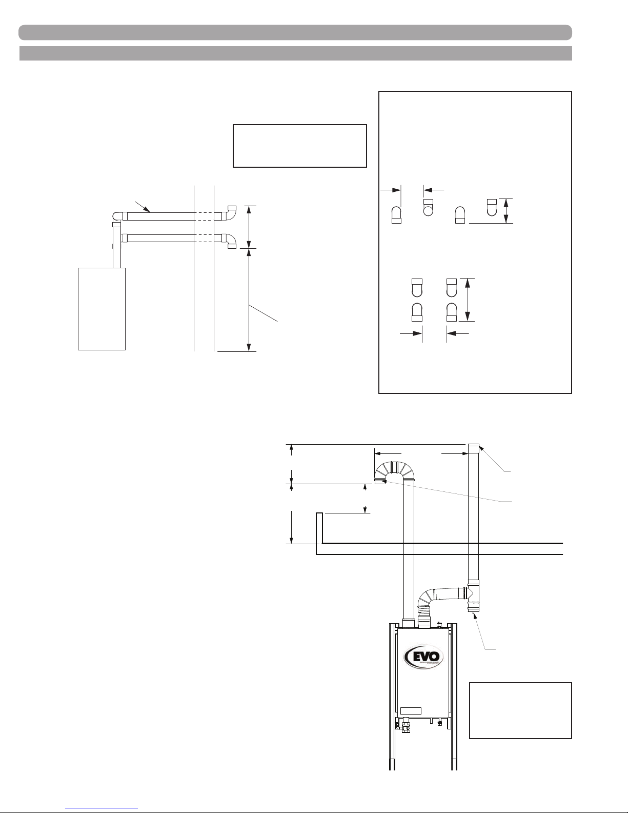
appliance
be
Drain
Vertical Run
maximum snow level
Right Side View
SHOWN OFFSET
FOR CLARITY
1/4" ft. slope to appliance
8"
24" Maximum
24" Maximum
B. VENTING THE EVO CONT.
(FIGURE 4-2) SIDEWALL VENT WITH DOWN
ELBOW (INTAKE) & UP ELBOW (EXHAUST)
PLEASE NOTE:
Exhaust must not terminate
beneath an overhang!
All horizontal runs must
be supported every 24"
EVO
Intake
Exterior wall
Exhaust
18" Minimum
24" Maximum
24" or 12" above
VENTING FOR MULTIPLE
UNITS, with vents all on same
horizontal plane, spaced at least
8 inches apart, and at level of
highest unit.
min.
Front Elevation
18" Minimum
- OR -
18" Minimum
whichever is greater
8"
min.
Front Elevation
(
Multiple Vents
)
**IMPORTANT NOTE: All vent pipes must be glued, properly supported and the exhaust must be pitched a
minimum of a 1/4" per foot back to the heater (to allow drainage of condensate). All stainless venting must be
sealed at each joint per manufacturer’s instructions.
ROOF
8" Minimum
Exhaust w/
Coupler &
Bird Screen
Air intake
90º Elbow w/
Bird Screen
1/4" per ft. slope to
All horizontal runs must
supported every 24"
Recommended
Fitting Before
(FIGURE 4-3) VERTICAL VENT
WITH DOUBLE ELBOW (INTAKE)
& COUPLING (EXHAUST)
**IMPORTANT NOTE: All vent pipes must be
18" Minimum
24" Maximum
24" or 12" above
Maximum snow level
whichever is greater
Parapet
Wall
If Air intake is below
Parapet wall. Air intake
must be Min. 10' away
,
Min. 12" Above
Parapet wall if
within 10' of wall
glued, properly supported and the exhaust must
be pitched a minimum of a 1/4" per foot back to
the heater (to allow drainage of condensate). All
stainless venting must be sealed at each joint per
manufacturer’s instructions.
PLEASE NOTE:
Intake must take into
account any parapet
walls!
34000 Autry Street, Livonia, MI 48150 | 800.968.5530 | Fax 734.419.0209 | www.hamiltonengineering.com | LIT91127US REV 5/2018
Page 24
Page 25
24"
Maximum
whichever
Recommended Drain
Fitting Before Vertical Run
B. VENTING THE EVO CONT.
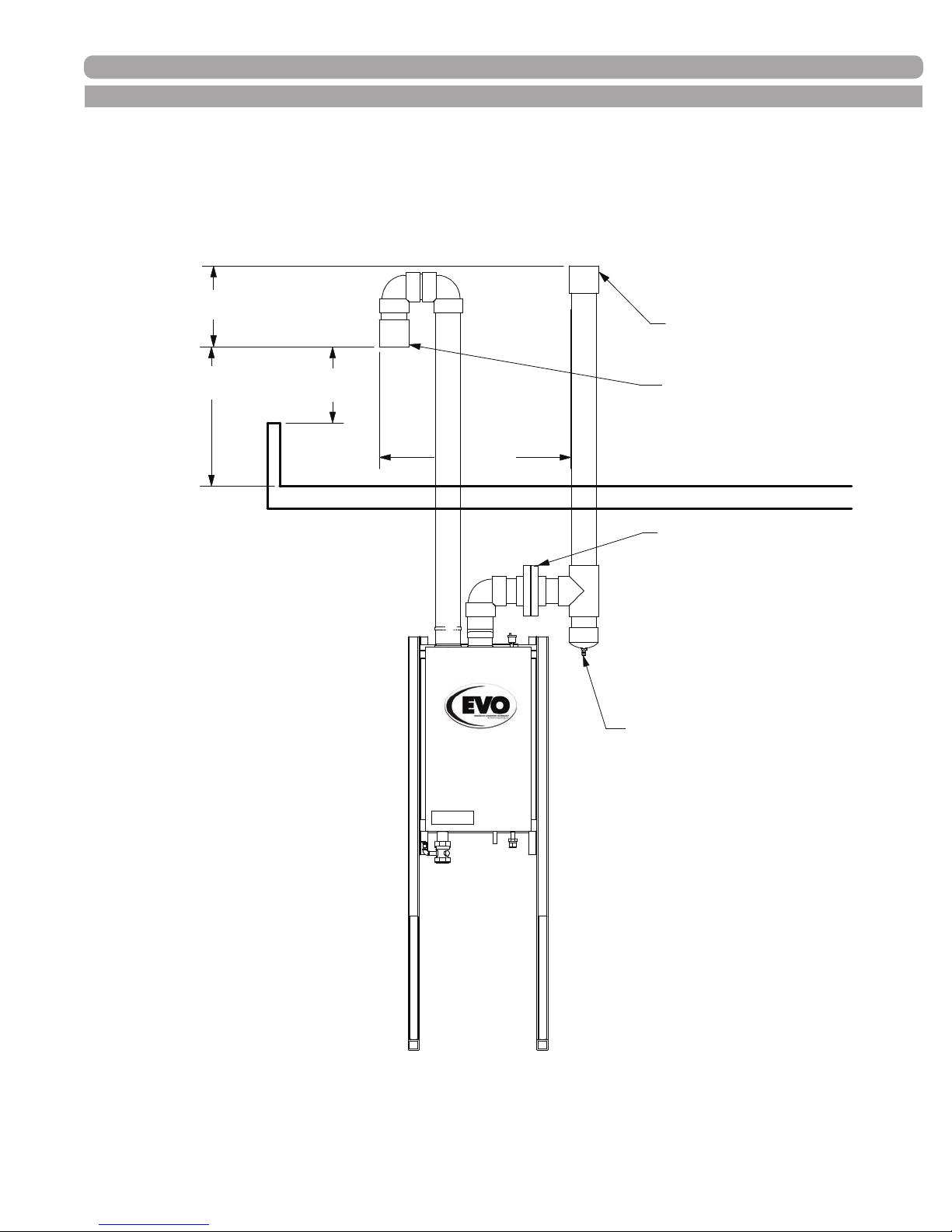
(FIGURE 4-4) VERTICAL VENT WITH PVC/CPVC
18" Minimum
24" Maximum
or 12" above
snow level
is greater
If Air intake is below
Parapet wall. Air intake
must be Min. 10' away
Parapet
Wall
Min. 12" Above
Parapet wall if
within 10' of wall
8" Minimum
ROOF
VENTING
Exhaust w/
Coupler &
Bird Screen
Air intake
90º Elbow w/
Bird Screen
Install Flanged Break Point to
Install Flanged Break Point To
Check Non-Return Damper
Check Non-Return Damper
During Anual Maintenance
During Annual Maintenance (CPVC only)
1/4” per ft. slope to appliance.
1/4" per ft. slope to appliance
All horizontal runs must be supported
All horizontal runs must be
every 24” (CPVC only)
supported every 24"
Recommended Drain
Fitting Before Vertical Run (CPVC only)
34000 Autry Street, Livonia, MI 48150 | 800.968.5530 | Fax 734.419.0209 | www.hamiltonengineering.com | LIT91127US REV 5/2018
Page 25
Page 26
B. VENTING THE EVO CONT.
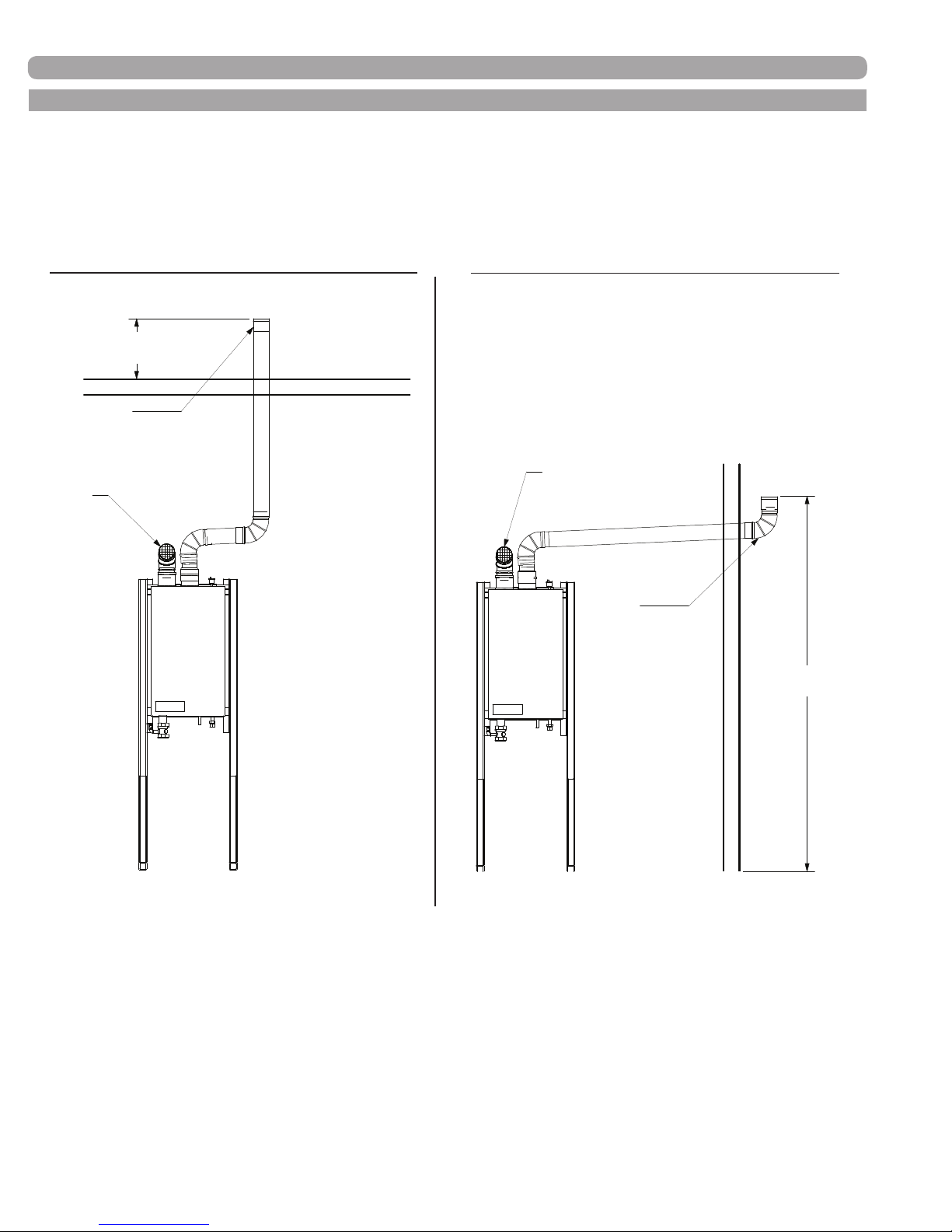
DIAGRAMS FOR ROOM AIR VENTING TERMINATION
If you’re using room air, your unit should be set up this way:
(FIGURE 4-5) VERTICAL TERMINATION
24" or 12" above
Maximum snow level
whichever is greater
Exhaust
90º Elbow with
Coupler & Bird Screen
Air intake
90º Elbow with
Bird Screen
1/4" per ft. slope to appliance
All horizontal runs must be
supported every 24"
(FIGURE 4-6) SIDEWALL TERMINATION
Air intake
90º Elbow with
Bird Screen
1/4" per ft. slope to appliance
All horizontal runs must be
supported every 24"
Exhaust
90º Elbow with
Coupler & Bird Screen
24" or 12" above
Maximum snow level
whichever is greater
As long as the boiler room remains under a positive pressure under all operating conditions of the building, this is a
perfectly acceptable option. Generally, all this requires is an external free air source; typically just two properly sized
openings to the outdoors. Installations done in this manner must comply with ANSI Z223.1, NFPA 54 - National Fuel
Gas Code 2009 section 9.3, and any specic local codes that may require additional combustion air be provided.
For more information, see Technical Bulletin - TB 003. This would be our preferred alternate to our standard manual
specications.
Note: Stated efciencies are based on ducted air; using room air may effect efciency.
34000 Autry Street, Livonia, MI 48150 | 800.968.5530 | Fax 734.419.0209 | www.hamiltonengineering.com | LIT91127US REV 5/2018
Page 26
Page 27
VENTING
CAUTION
Flue Gas will condense as it exits the vent termination. This condensate can
freeze on exterior building surfaces which may cause discoloration of these
surfaces. Consideration should be given to the plume of condensation that exits
the exhaust which may affect the cosmetic appearance of the building.
C. INLET AIR VENT
You may use the same material as used for exhaust or any material that is the same diameter that provides a
pressure tight connection. THIS IS ONLY FOR INLET AIR, NOT FOR EXHAUST PIPING!
The air inlet must be a minimum of 12" vertically above the maximum snow level. It is very important that there
are no other vents, chimneys or air inlets in any direction for at least 48".
All venting must be properly supported. The EVO is not intended to support any venting whatsoever. All
piping, glue, solvents, cleaners, ttings and components, must conform to ASTM (American Society for Testing
and Materials), and ANSI (American National Standards Institute).
D. VENTING RUNS THAT EXCEED MAXIMUM COMBINED LENGTH
If the combined venting length of a heater’s exhaust/inlet air system exceeds the Maximum Combined
Length called out in Table 4-1, Page 21, contact Hamilton Engineering, Inc. for an engineered venting
calculation. Do not proceed without calling Hamilton Engineering, Inc. at 800.968.5530 or 734.419.0200.
VENT CALCULATION EXAMPLE: Installation requires the following material for both inlet and exhaust piping for
the EVO HW 199.1 (maximum combined equivalent length is 100 feet).
Required: 6 Pcs. 90° elbow (6 x 5 = 30 equivalent feet) = 30 equivalent feet
Required: 20' of Plastic PVC Pipe (20 x 1 = 20 equivalent feet) = 20 equivalent feet
Required: Inlet air in vertical termination (2) 90° elbows + bird screen) = 11 equivalent feet
Required: Exhaust coupling = 1 equivalent foot
Total Friction Loss in equivalent feet = 62 equivalent feet
THIS VENT SYSTEM IS OK!
DANGER
The EVO is not intended to be common vented with any other existing
appliance! Multiple EVO products may be common vented, only if using an
engineered system by Hamilton Engineering, Inc.
E. HEATER REMOVAL FROM AN EXISTING COMMON VENT SYSTEM
At the time of removal of an existing heater, the following steps shall be followed with each appliance that
remains connected to the common venting system placed in operation, while the other appliances that remain
connected to common venting system are not operating.
1. Seal any unused openings in the common venting system. The EVO venting is NOT to be combined
with this older venting system!
2. Visually inspect the venting system for proper size and horizontal pitch to determine if there is
blockage, leakage, corrosion or other deciencies that could cause an unsafe condition.
34000 Autry Street, Livonia, MI 48150 | 800.968.5530 | Fax 734.419.0209 | www.hamiltonengineering.com | LIT91127US REV 5/2018
Page 27
Page 28
VENTING
E. HEATER REMOVAL FROM AN EXISTING COMMON VENT SYSTEM CONT.
3. If practical, close all building doors, windows and all doors between the space in which the
appliance remains connected to the common venting system and other spaces in the building. Turn
on clothes dryers and any appliances not connected to the common venting system. Turn on any
exhaust fans, such as range hoods and bathroom exhausts, at maximum speed. Do not operate a
summer exhaust fan. Close all replace dampers.
4. Place the appliance being inspected in operation. Follow the lighting instructions. Adjust the
thermostat so the appliance will operate continuously.
5. Test for spillage at the draft hood relief opening after 5 minutes of main burner operation. Use the
ame of a match or candle or smoke from a cigarette.
6. After it has been determined that each appliance remaining connected to common venting system
properly vents when tested as outlined, return doors, windows, exhaust fans, replace dampers and
any other gas burning appliance to their previous condition of use.
7. Any improper operation of the common venting system should be corrected so the installation con
forms with the National Fuel Gas Code, ANSI Z223.1. When resizing any portion of the common
venting system, the common venting system should be resized to approach the minimum size as
determined using the appropriate tables in Appendix G in the National Fuel Gas Code, ANSI Z 223.1
WARNING
In a common vent system, DO NOT POWER THE UNIT OFF! Equipment damage
may occur. To disable operation, turn off gas, NOT power. If you have any questions,
please call Hamilton Engineering Technical Support at 800.968.5530.
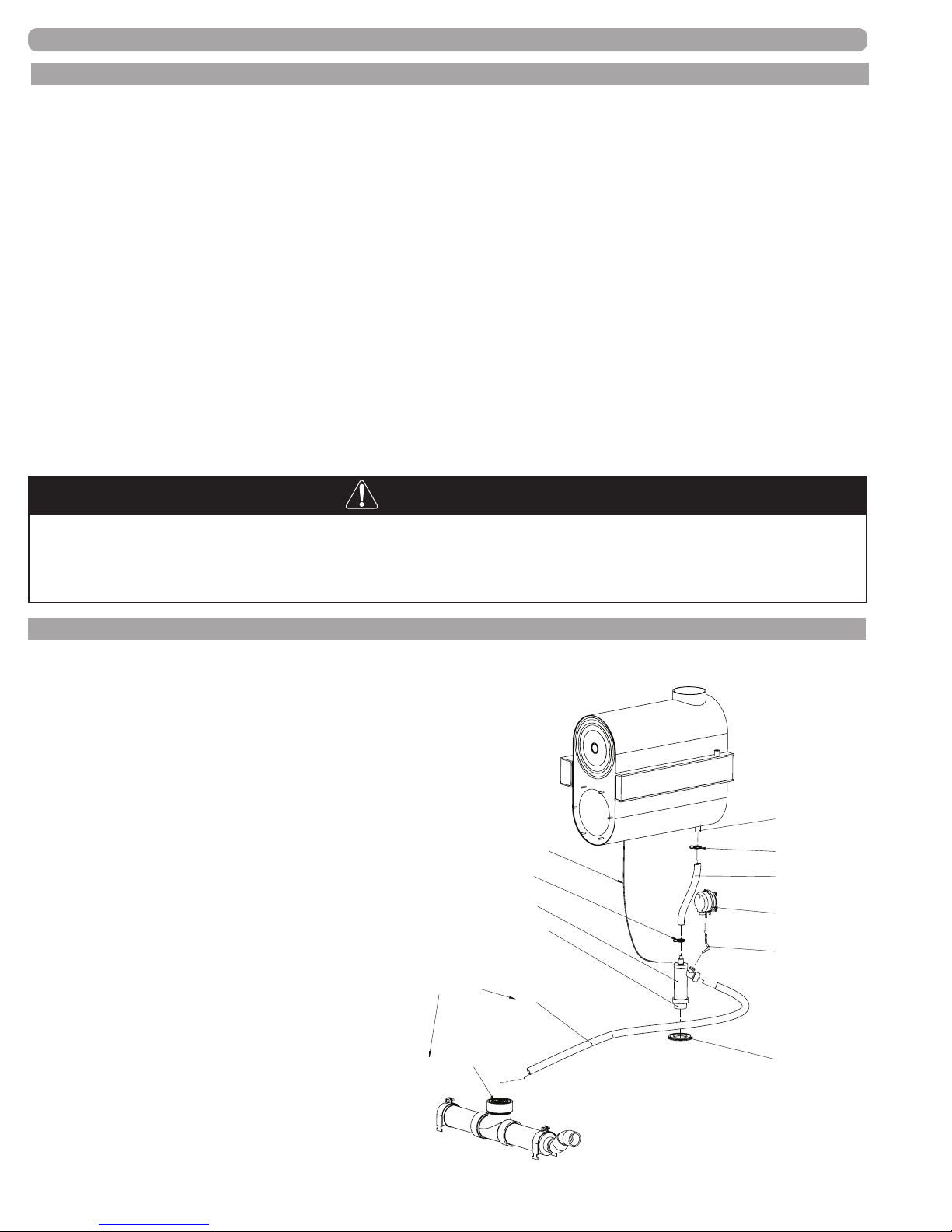
F. CONDENSATE REQUIREMENTS
This is a condensing high efciency appliance, therefore this unit
has a condensate removal system. Condensate is nothing more
than water vapor derived from the combustion products, similar
to an automobile when it is initially started. This condensate does
have a low pH and should be treated with a Condensate Neutral-
izer Filter. This lter contains either lime or marble rocks, which
will neutralize the condensate. The outlet of the lter is sized
for 1.5" PVC pipe. It is very important that the condensate
line is sloped away from and down to a suitable inside
drain. A condensate neutralizer and a condensate pump
kit are available from Hamilton Engineering, Inc. It is also
very important that the condensate line is not exposed
to freezing temperatures, or any other type of
blockage. Plastic tubing or PVC pipe should be
the only materials used for the condensate line.
Steel, brass, copper or others will be subject to
corrosion and deterioration. A second vent may
DO NOT SEAL THE
OPENING BETWEEN
THESE PIPES, OR
PRODUCT DAMAGE
MAY OCCUR.
be necessary to prevent condensate line vacuum
CONDENSATE HOSE
FROM AIR INLET
HOSE CLIP
DRAIN TRAP
CLEAN OUT CAP
DRAIN TUBE
lock if a long horizontal run is used. The EVO
appliance has an automatic safety device that will
shut it down in the event of a condensate drain
ATMOSPHERIC
GRAVITY DRAIN
blockage. Please test annually.
Maximum volume of condensate produced is
11 gallons per hour per 1,000,000 BTU of gas burned.
(FIGURE 4-7)
CONDENSATE DRAIN DETAIL
NOTE:
Heat
exchanger
MUST be level
or pitched
slightly to
the rear!
CONDENSATE DRAIN FROM
HEAT EXCHANGER
HOSE CLIP
HOSE FROM DRAIN TO TRAP
BLOCKED DRAIN SWITCH
HOSE FROM SWITCH
TO TRAP
GROMMET FOR CABINET
34000 Autry Street, Livonia, MI 48150 | 800.968.5530 | Fax 734.419.0209 | www.hamiltonengineering.com | LIT91127US REV 5/2018
Page 28
Page 29
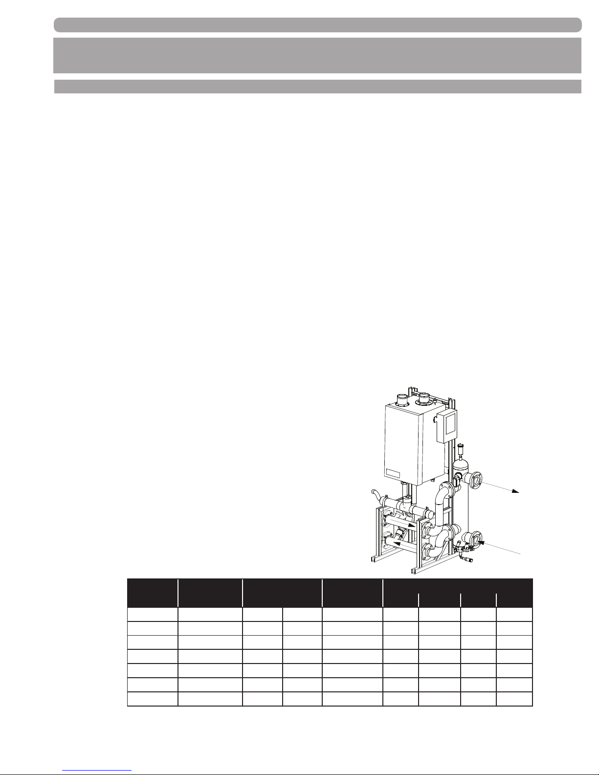
PIPING
PART 5. PIPING
A. HYDRONIC HEATING BOILER PIPING
The EVO is designed to function in a closed loop (minimum) 12 PSI System. Never let the EVO operate without a
minimum of 10 PSI water pressure, this assures that the EVO heat exchanger can be completely purged of air, failure
to do so could cause damage. It is important to note that the EVO Boiler is ow dependent for proper efciency and
life expectancy; therefore, primary-secondary piping or use of a low loss header design is always recommended, as
shown in the Figure 5-1 below. Each EVO Heating Boiler System should have an Air Eliminator, in addition to the heat
exchanger mounted air vent, which will remove air from the Hydronic System. Always follow good piping practices. Observe minimum 1" clearance to combustibles around all uninsulated hot water pipes,
are not protected by non-combustible materials. On an EVO installed above the level of the highest heat transfer
device, some state and local codes require a low water cut off device at the time of installation by the installer. A
water ow switch is provided as standard and will take the place of a low water cut-off. If the EVO supplies hot
water to heating coils in air handler units, ow control valves or other devices must be installed to prevent gravity
circulation of boiler water in the coils during the cooling cycle.
Basic piping connection steps are listed below. A drawing, specic to your application can be obtained from your distributor or Hamilton Engineering, Inc., which will guide you through proper installation of the EVO.
1) Pipe properly, in accordance with generally accepted piping principals or Hamilton Engineering
specic documents.
2) Connect system return to the pipe entering the EVO closest to the back.
3) Connect system supply to the pipe leaving the EVO containing the Relief Valve.
4) Install Drain Valve on system supply.
or when openings around pipes
Note: the EVO can not be drained of water without purging the unit with air pressure, 15 PSI minimum.
The system’s air vent must be closed during this process.
(FIGURE 5-1) BOILER PIPING
To System
From System
(TABLE 5-1) BOILER PIPING
Model
HW 79 4.4 @ 7.9' 34.6º F 19.2º C PMP 90302 1" 1" 1" 1.5"
HW 129 4.4 @ 7.9' 58.9º F 32.7º C PMP 90302 1" 1" 1" 1.5"
HW 179 6.6 @ 7.9' 53.7º F 29.8º C PMP 90302 1" 1" 1.5" 1.5"
HW 199.1 6.6 @ 7.9' 57.6º F 32.0º C PMP 90302 1" 1" 1.5" 1.5"
HW 299 11 @ 9.3' 51.8º F 28.8º C PMP 90304 1.5" 1.5" 2" 2"
HW 399 17.6 @ 8.5' 43.2º F 24.0º C PMP 90304 1.5" 2" 2" 2.5"
HW 599 26.4 @ 9.4' 45.3º F 25.2º C PMP 90310 1.5" 2" 2.5" 3"
Boiler Only
GPM ∆P
Design ∆T
Pump
Supplied
Minimum Manifold Pipe Size
Single Double Triple Quad
Note: Flow rates shown above are for clean, closed loop systems.
34000 Autry Street, Livonia, MI 48150 | 800.968.5530 | Fax 734.419.0209 | www.hamiltonengineering.com | LIT91127US REV 5/2018
Page 29
Page 30
HWR Hot Water Return
HWS
Hot Water Supply
CD Condensate Drain
CW
Cold Water
Pump
Ball valve
Check valve
Thermometer
Air vent
Drain valve
Hamilton System Separator
Zone Header w/ stand
ZH
HSS
LEGEND
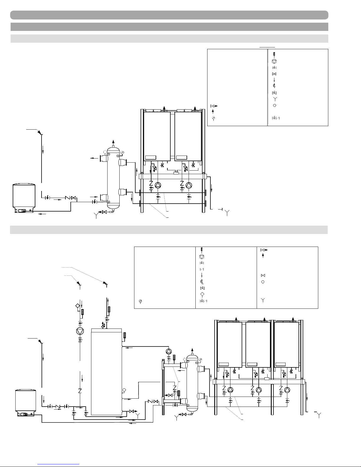
B. BOILER SCHEMATIC DRAWINGS
LEGEND
HWR Hot Water Return
HWS Hot Water Supply
CD Condensate Drain
B EVO Boiler Stand Mounted
CNK Condensate Neutralizer
ET
Expansion Tank
CW Cold Water
Pump
Ball valve
Flow direction
Pressure Relief valve
Thermometer
Fill Valve
Hamilton System Separator
Gas cock
Drain valve
Air vent
Floor Drain
HSS
Temperature &
Pressure gauge
Temperature Sensor
TS
Boiler pumpBP
Ball Valve with built-in
Check Valve
LEGEND
Two boiler schematic to Hamilton System Separator
PIPING
Make-up
Water
ET
CW
To System
From System
HWS Hot Water Supply
HWR Hot Water Return
CW Cold Water
CD Condensate Drain
B EVO Boiler Stand Mounted
Expansion Tank
ET
CNK Condensate Neutralizer
HSS
Hamilton System Separator
Drain valve
Air vent
Temperature &
Pressure gauge
B-1
TS
HSS
CNK
BP-1
B-2
CD
Supply to HSS
CD
BP-2
CD
Thermometer
Pump
Ball valve
Fill Valve
Flow direction
Pressure Relief valve
Gas cock
Floor Drain
TS
Temperature Sensor
Boiler pumpBP
Ball Valve with built-in
Check Valve
Return from HSS
Three boiler schematic to Hamilton System Separator with one zone for indirect hot water tank
LEGEND
Make-up
Water
ET
To System
From System
CW
HWR
HWR
HWS
HWR Hot Water Return
B EVO Boiler Stand Mounted
Indirect DHW Tank
IHET
HWS
Expansion Tank
ET
CNK Condensate Neutralizer
IHET
Temperature &
Pressure gauge
IHET
TS
Hot Water Supply
CW
Cold Water
CD Condensate Drain
B EVO Boiler Stand Mounted
Indirect DHW Tank
Expansion Tank
ET
CNK Condensate Neutralizer
Temperature &
Pressure gauge
ZP-1
TS
ZH
Flow direction
Pressure Relief valve
Ball valve with built-in
Check valve
HSS
Thermometer
Pump
Ball valve
Check valve
Gas cock
Flow direction
Aquastat
Pressure Relief valve
Gas cock
Aquastat
Ball valve with built-in
Check valve
B-1
CD
CNK
BP-1
Drain valve
Air vent
Fill valve
HSS
Hamilton System Separator
TS
Temperature Sensor
ZH
Zone Header w/ stand
Boiler pump
BP
Fill valve
TS
Zone pump
ZP
Temperature Sensor
Floor Drain
Boiler pump
BP
Zone pump
ZP
Floor Drain
B-3B-2
CD
BP-2
BP-3
CD
Supply to HSS
Return from HSS
IMPORTANT NOTE: The above are representative drawings; must conform to local codes. Consult factory for Custom System Solutions.
34000 Autry Street, Livonia, MI 48150 | 800.968.5530 | Fax 734.419.0209 | www.hamiltonengineering.com | LIT91127US REV 5/2018
Page 30
CD
Page 31

C. FILL & PURGE HEATING SYSTEM
1) Attach hose to balance and purge hose connector and run to drain.
2) Close the other side of the balance and purge valve.
3) Open rst zone balance and purge valve, so as to let the water ow out of the hose. If zone valves
are used, open zone valves one at a time, manually. (NOTE: please check manufacturer’s
instructions prior to opening valves manually, so as not to damage the valve.)
4) Manually operate ll valve regulator. When water runs out of hose, connected to the balance and
purge valve, in steady stream (with no air bubbles), close balance and purge valve to stop the
water from owing. Disconnect hose and connect to next zone to be purged.
5) Repeat procedure for additional zones (one at a time).
Upon completion, make sure that the ll valve is in automatic position and each zone balance and purge valve
is in the open position and zone valves are positioned for automatic operation.
NOTE: Installations that incorporate Standing Iron Radiators and systems with manual high point vents:
Follow the above procedure, then starting with nearest manual air vent, open vent until water ows out; close
vent. Repeat procedure, working your way toward furthest air vent. It may be necessary to install a basket strainer
or ltration in an older hydronic system where larger amounts of sediment may be present. Periodic cleaning of
the strainer may be necessary.
For boiler water and/or odd water systems, please make note of these additional guidelines:
• Thoroughly ush the system (without boiler connected) to remove sediment. The high-efciency
heat exchanger can be damaged by build-up or corrosion due to sediment.
• Do not use petroleum-based cleaning or sealing compounds in the boiler system. Gaskets and
seals in the system may be damaged. This can result in substantial property damage.
• Do not use ‘homemade cures’ or ‘boiler patent medicines’. Serious damage to the boiler, personnel,
and/or property may result.
• Continual fresh make-up water will reduce boiler life. Mineral buildup in the heat exchanger
reduces heat transfer, overheats the stainless steel heat exchanger, and causes failure.
Addition of oxygen carried in by makeup water can cause internal corrosion in system
components. Leaks in boiler or piping must be repaired at once to prevent makeup water.
D. REMOVING AIR FROM THE HEAT EXCHANGER
The EVO 299–599 (it is not necessary on an EVO 79–199.1) has an automatic air vent on the top of the appli-
ance and the air vent cap must be loosened to allow trapped air to escape when the appliance is initially lled
and put into operation. If this air vent should start to leak, there are two possible solutions:
a. Close the cap—the air vent is not needed anymore after the heat exchanger has been purged of air.
This air vent MUST be operable if the appliance is drained and relled.
b. Replace the air vent. When replacing the air vent, the water must be shut off and pressure released rst.
34000 Autry Street, Livonia, MI 48150 | 800.968.5530 | Fax 734.419.0209 | www.hamiltonengineering.com | LIT91127US REV 5/2018
Page 31
Page 32
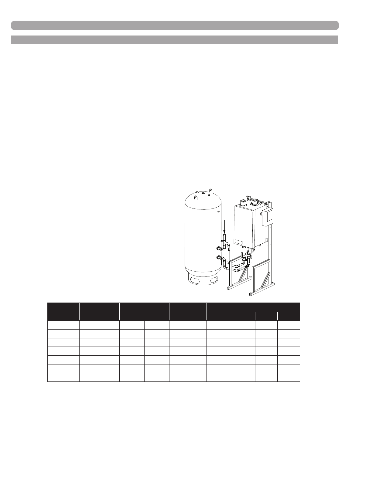
E. WATER HEATING PIPING
1) Use only the pipe sizes shown and a pump meeting the listed specications in the following tables:
*Note: Individual Appliance Piping pressure drop used in the tables is based on 20 feet of straight
pipe, 6 elbows, 2 tees, 2 full port ball valves and 2 unions.
2) The city cold water supply to the water heating system should be connected between the heater
outlet and the storage tank or the storage tank directly. This will help minimize unnecessary short
cycling due to small hot water draws. Higher efciency can be obtained through use of our optional
CWIS
™
- Cold Water Injection System in any Hamilton Storage Tank.
3) Isolation valves should be installed on each heater and on the cold and hot water system connections.
Upon completion of piping, ll and properly purge of all air. Open all valves and start circulating pump. Consult
Hamilton Engineering for specic piping diagrams for your application at 800.968.5530.
NOTE: Minimum pump selection is based on piping sizes shown above and water hardness not to
exceed 15 grains per gallon and total maximum equivalent piping length of 60 feet.
City Water
Connection
(FIGURE 5-2) HEATER PIPING
(TABLE 5-2) WATER HEATER PIPING
Model GPM ∆P* Design ∆T
Pump
Supplied
HW 79 6.6 @ 19.9’ 23.5º F 13.1º C PMP 90305 1” 1.5” 1.5” 2”
HW 129 6.6 @ 19.9’ 40.1º F 22.2º C PMP 90305 1” 1.5” 1.5” 2”
HW 179 9.9 @ 21.8’ 36.6º F 20.3º C PMP 90305 1” 1.5” 1.5” 2”
HW 199.1 9.9 @ 21.8’ 39.2º F 21.8º C PMP 90305 1” 1.5” 1.5” 2”
HW 299 16.5 @ 22.9’ 35.3º F 19.6º C PMP 90307 1.5” 2” 2” 2.5”
HW 399 26.4 @ 20.3’ 29.4º F 16.3º C PMP 90309 2” 2” 2.5” 3”
HW 599 39.6 @ 23.6’ 30.9º F 17.1º C PMP 90309 2” 2.5” 3” 4”
34000 Autry Street, Livonia, MI 48150 | 800.968.5530 | Fax 734.419.0209 | www.hamiltonengineering.com | LIT91127US REV 5/2018
Page 32
Minimum Manifold Pipe Size
Single Double Triple Quad
*Water heater and piping as described above.
Page 33
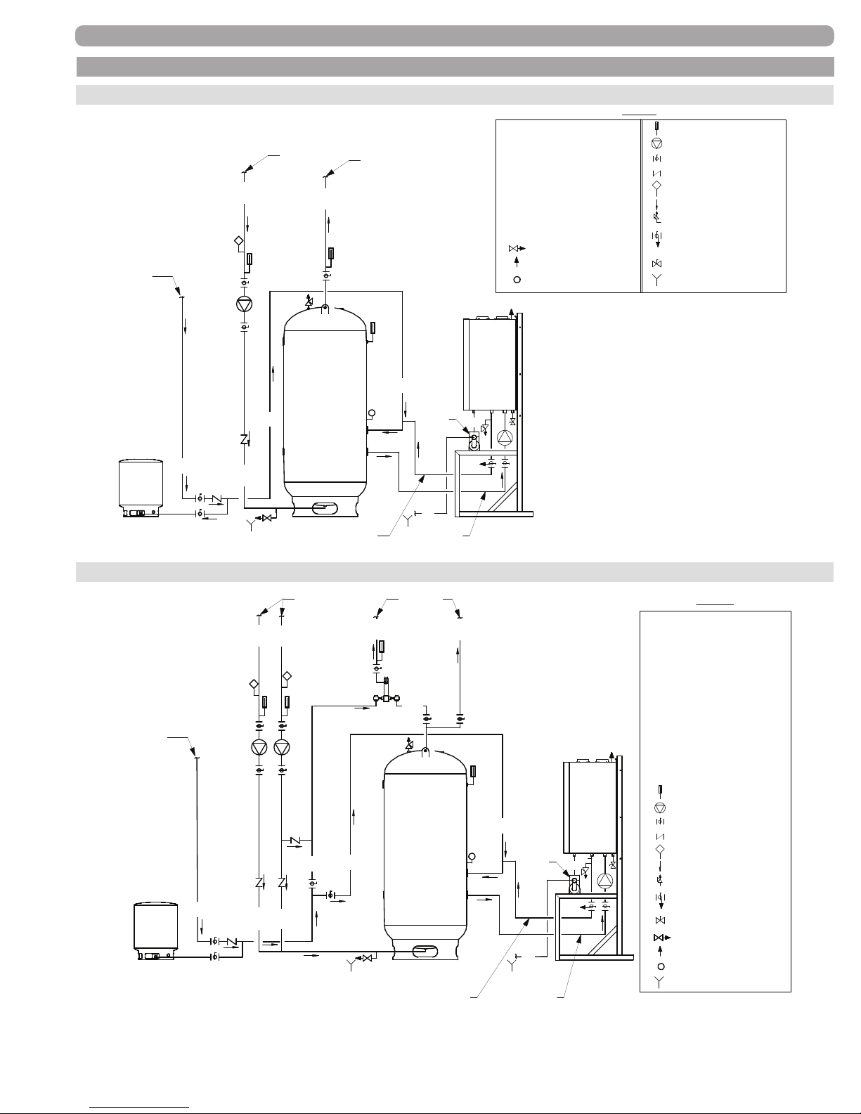
F. WATER HEATING SCHEMATIC DRAWINGS
From TankTo Tank
LEGEND
PIPING
One water heater schematic to single tank
Make-up
Water
ET
From System
HWR
HET
CW
CW
HWR
To System
HWS
TS
CW
CNK
HWS Hot Water Supply
HWR Hot Water Return
CW Cold Water
CD Condensate Drain
WH Water Heater with Stand
Storage Tank
HET
ET Expansion Tank
CNK Condensate Neutralizer
Drain valve
Air vent
TS
Temperature Sensor
WH
CD
LEGEND
Thermometer
Pump
Ball valve
Check valve
Aquastat
Flow direction
Pressure Relief valve
Ball Valve with built-in Drain
Valve
Gas cock
Floor drain
CD
One water heater schematic to single tank with mixing valves
To SystemFrom System
Make-up
Water
ET
CW
HWR
HWR
TWR
TWR
CW
TWS
TMV
HWS
HET
CW
HWS
CW
TS
CNK
CD
From TankTo Tank
LEGEND
HWS Hot Water Supply
HWR
Hot Water Return
CW Cold Water
TWS
Tempered Water Supply
TWR Tempered Water Return
CD Condensate Drain
WH Water Heater with Stand
Storage Tank
HET
ET Expansion Tank
CNK Condensate Neutralizer
TMV
Termostatic Mixing Valve
WH
CD
Thermometer
Pump
Ball valve
Check valve
Aquastat
Flow direction
Pressure Relief valve
Ball Valve with built-in Drain
Valve
Gas cock
Drain valve
Air vent
TS
Temperature Sensor
Floor drain
IMPORTANT NOTE: The above are representative drawings; must conform to local codes. Consult factory for Custom System Solutions.
34000 Autry Street, Livonia, MI 48150 | 800.968.5530 | Fax 734.419.0209 | www.hamiltonengineering.com | LIT91127US REV 5/2018
Page 33
Page 34
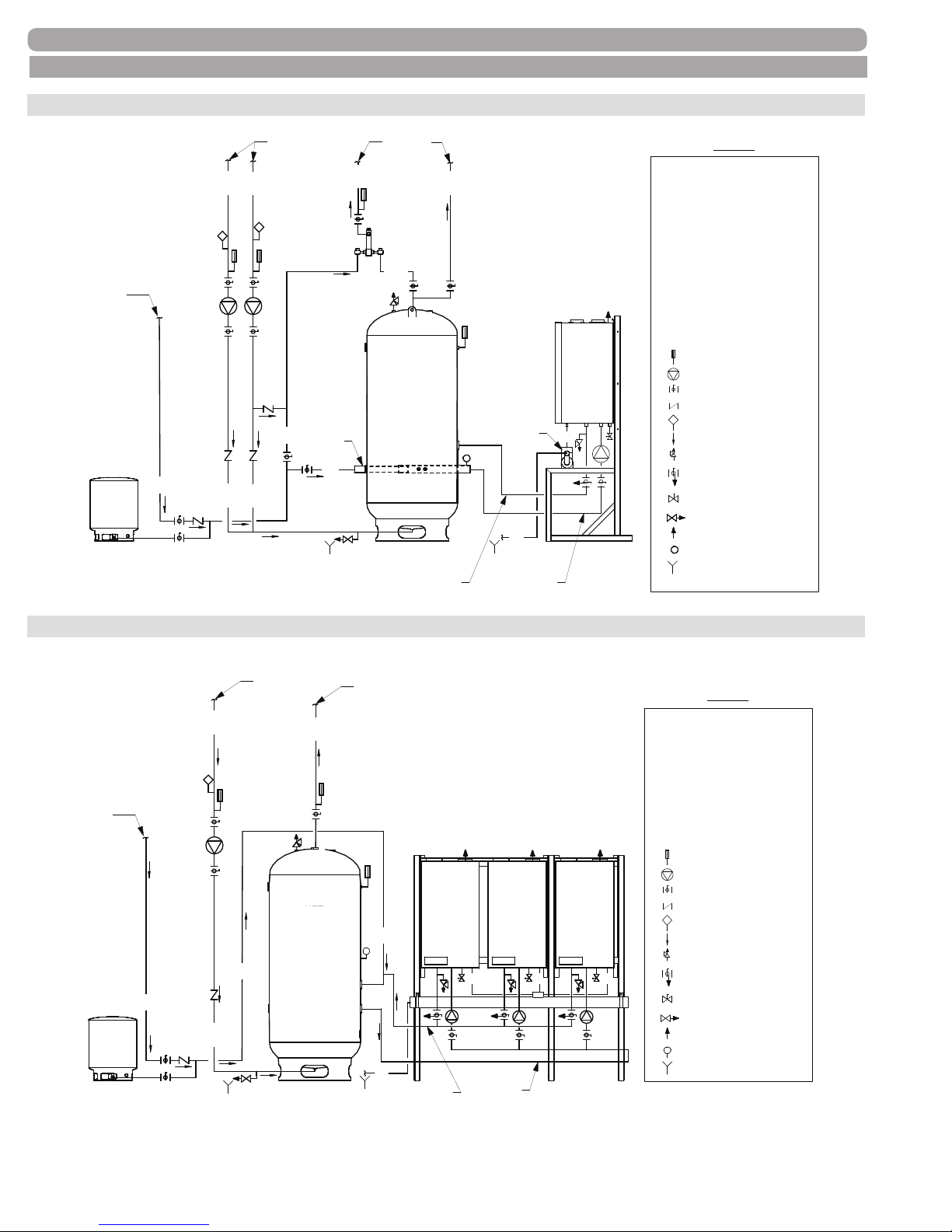
F. WATER HEATING SCHEMATIC DRAWINGS CONT.
PIPING
One water heater schematic to single tank with mixing valve and CWIS
To SystemFrom System
CWIS
CW
TWS
TMV
HWS
HET
HWS
WH
CNK
TS
CD
CD
From TankTo Tank
Make-up
Water
ET
CW
HWR
HWR
TWR
CW
TWR
™
LEGEND
HWS Hot Water Supply
HWR
Hot Water Return
CW Cold Water
TWS
Tempered Water Supply
TWR Tempered Water Return
CD Condensate Drain
WH Water Heater with Stand
Storage Tank
HET
Expansion Tank
ET
CNK Condensate Neutralizer
TMV
Termostatic Mixing Valve
Thermometer
Pump
Ball valve
Check valve
Aquastat
Flow direction
Pressure Relief valve
Ball Valve with built-in Drain
Valve
Gas cock
Drain valve
Air vent
TS
Temperature Sensor
Floor drain
Cold Water Injection System
CWIS
Three water heater schematic to single tank
Make-up
Water
ET
CW
HWRHWR
From System
CW
HET
HET
HWS
To System
CW
TS
CD
WH-1
To Tank
CD
CNK
From Tank
LEGEND
HWS Hot Water Supply
HWR
Hot Water Return
CW Cold Water
CD Condensate Drain
WH Water Heater with Stand
Storage Tank
HET
ET Expansion Tank
CNK Condensate Neutralizer
Thermometer
Pump
Ball valve
WH-3WH-2
CD
CD
Check valve
Aquastat
Flow direction
Pressure Relief valve
Ball Valve with built-in Drain
Valve
Gas cock
Drain valve
Air vent
TS
Temperature Sensor
Floor drain
IMPORTANT NOTE: The above are representative drawings; must conform to local codes. Consult factory for Custom System Solutions.
34000 Autry Street, Livonia, MI 48150 | 800.968.5530 | Fax 734.419.0209 | www.hamiltonengineering.com | LIT91127US REV 5/2018
Page 34
Page 35
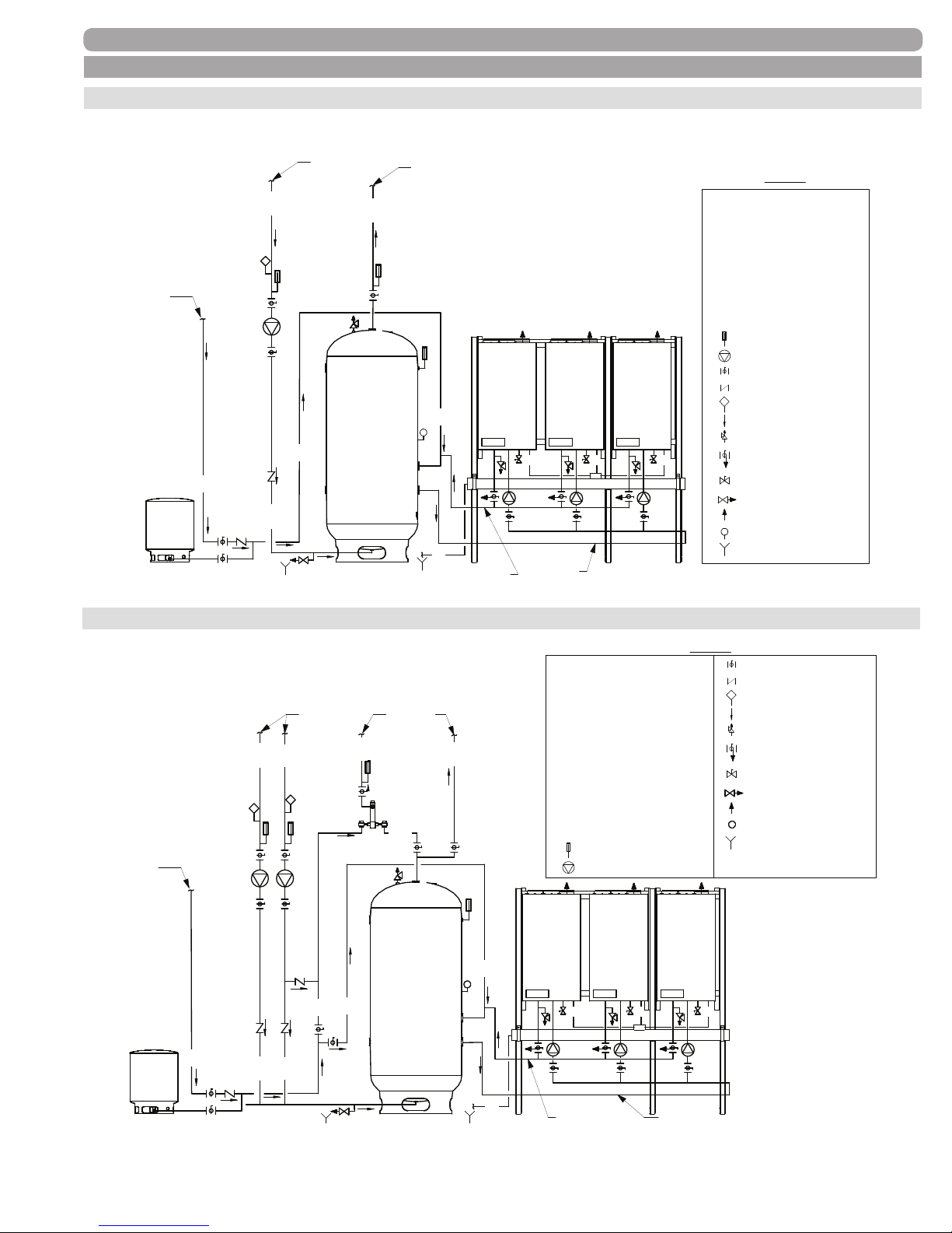
F. WATER HEATING SCHEMATIC DRAWINGS CONT.
Three water heater schematic to single tank
PIPING
Make-up
Water
ET
CW
HWRHWR
From System
CW
HET
HET
HWS
To System
CW
TS
CD
WH-1
To Tank
CD
CNK
From Tank
LEGEND
HWS Hot Water Supply
HWR
Hot Water Return
CW Cold Water
CD Condensate Drain
WH Water Heater with Stand
Storage Tank
HET
ET Expansion Tank
CNK Condensate Neutralizer
Thermometer
Pump
Ball valve
WH-3WH-2
CD
CD
Check valve
Aquastat
Flow direction
Pressure Relief valve
Ball Valve with built-in Drain
Valve
Gas cock
Drain valve
Air vent
TS
Temperature Sensor
Floor drain
Three water heater schematic to single tank with mixing valve
HWS Hot Water Supply
HWR
Hot Water Return
Cold Water
CW
TWS
Tempered Water Supply
TWR Tempered Water Return
CD Condensate Drain
WH Water Heater with Stand
HET Storage Tank
Expansion Tank
ET
CNK Condensate Neutralizer
TMV
Termostatic Mixing Valve
Thermometer
Pump
CD
CNK
Make-up
Water
ET
CW
HWR
HWR
TWR
TWR
CW
CW
TWS
TMV
To SystemFrom System
HWS
HET
HWS
WH-1
CW
TS
LEGEND
Ball valve
Check valve
Aquastat
Flow direction
Pressure Relief valve
Ball Valve with built-in Drain
Valve
Gas cock
Drain valve
Air vent
TS
Temperature Sensor
Floor drain
WH-3WH-2
CD
CD
IMPORTANT NOTE: The above are representative drawings; must conform to local codes. Consult factory for Custom System Solutions.
34000 Autry Street, Livonia, MI 48150 | 800.968.5530 | Fax 734.419.0209 | www.hamiltonengineering.com | LIT91127US REV 5/2018
CD
Page 35
From TankTo Tank
Page 36
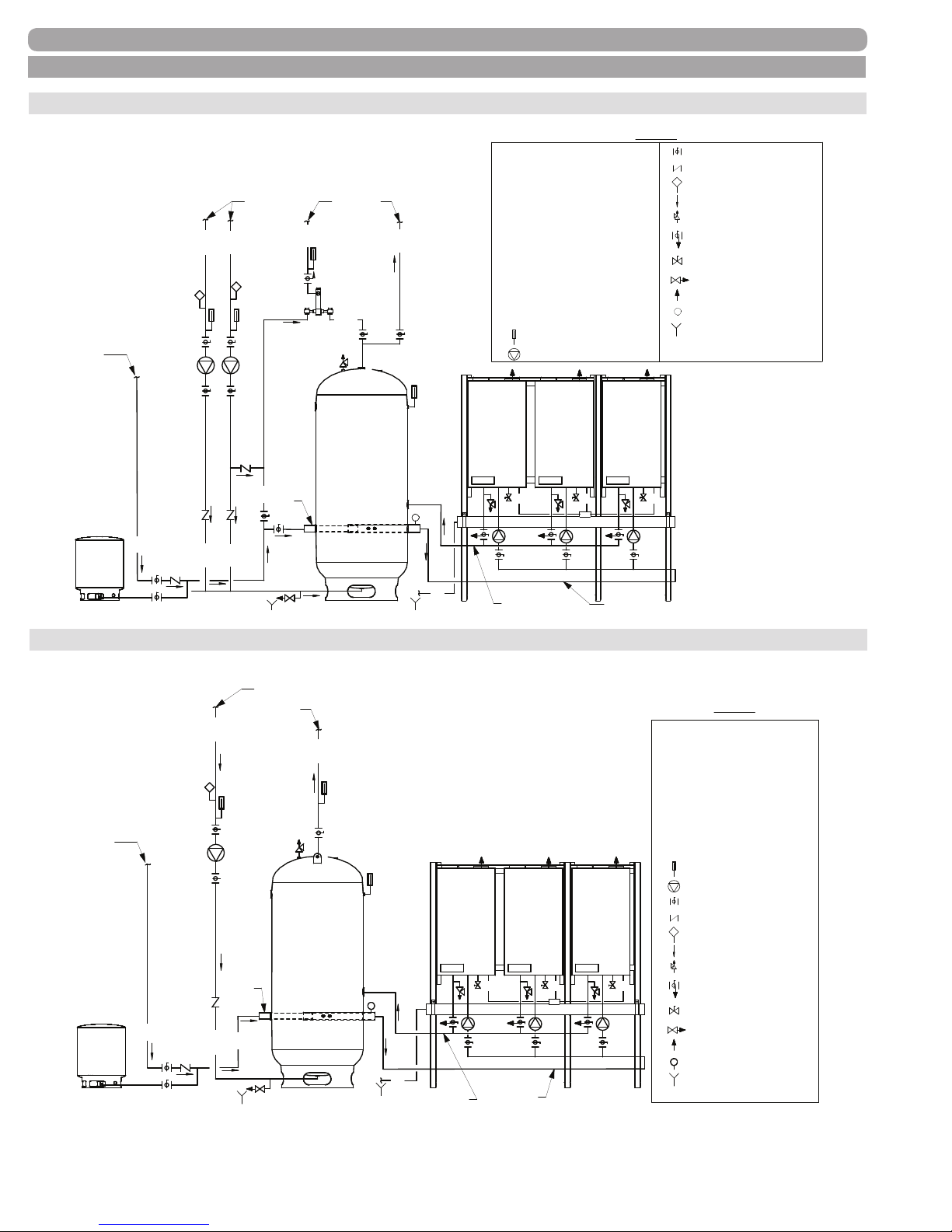
LEGEND
F. WATER HEATING SCHEMATIC DRAWINGS CONT.
PIPING
Three water heater schematic to single tank with mixing valve and CWIS
HWS Hot Water Supply
HWR
Hot Water Return
Cold Water
CW
TWS
Tempered Water Supply
TWR Tempered Water Return
CD Condensate Drain
WH Water Heater with Stand
HET Storage Tank
Expansion Tank
ET
CNK Condensate Neutralizer
TMV
Termostatic Mixing Valve
Thermometer
Pump
WH-3WH-2
CD
CNK
CD
Make-up
Water
ET
CW
HWR
HWR
TWR
TWR
CW
CWIS
TWS
TMV
To SystemFrom System
HWS
HET
HWS
WH-1
TS
™
Ball valve
Check valve
Aquastat
Flow direction
Pressure Relief valve
Ball Valve with built-in Drain
Valve
Gas cock
Drain valve
Air vent
TS
Temperature Sensor
Floor drain
Cold Water Injection System
CWIS
CD
CD
Three water heater schematic to single tank with CWIS
From System
To System
HWRHWR
HWS
Make-up
Water
HET
CWIS
TS
ET
CW
CW
CD
WH-1
To Tank
CNK
From Tank
From TankTo Tank
™
LEGEND
HWS Hot Water Supply
HWR
WH-3WH-2
CD
CD
CD
Hot Water Return
CW Cold Water
CD Condensate Drain
WH Water Heater with Stand
Storage Tank
HET
ET Expansion Tank
CNK Condensate Neutralizer
Thermometer
Pump
Ball valve
Check valve
Aquastat
Flow direction
Pressure Relief valve
Ball Valve with built-in Drain
Valve
Gas cock
Drain valve
Air vent
TS
Temperature Sensor
Floor drain
Cold Water Injection System
CWIS
IMPORTANT NOTE: The above are representative drawings; must conform to local codes. Consult factory for Custom System Solutions.
34000 Autry Street, Livonia, MI 48150 | 800.968.5530 | Fax 734.419.0209 | www.hamiltonengineering.com | LIT91127US REV 5/2018
Page 36
Page 37
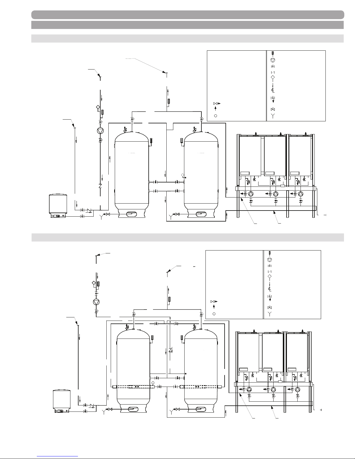
F. WATER HEATING SCHEMATIC DRAWINGS CONT.
LEGEND
From Tank
To Tank
LEGEND
From Tank
To Tank
Three water heater schematic to two tanks
PIPING
Make-up
Water
ET
From System
CW
To System
HWRHWR
CW
HWS
HWS
CW
HETHET HETHET
TS
HWS Hot Water Supply
HWR Hot Water Return
CW Cold Water
CD Condensate Drain
WH Water Heater with Stand
Storage Tank
HET
ET Expansion Tank
CNK Condensate Neutralizer
Drain valve
Air vent
TS
Temperature Sensor
WH-1
CNK
Thermometer
Pump
Ball valve
Check valve
Aquastat
Flow direction
Pressure Relief valve
Ball Valve with built-in Drain
Valve
Gas cock
Floor drain
WH-3WH-2
CD
CD
CD
CD
Three water heater schematic to two tanks with CWIS
From System
To System
HWS
HETHET
HWR
Make-up
Water
ET
CW
HWR
CW
HWR
CW
CW
HW
CW
HETHET
TS
™
HWS Hot Water Supply
HWR Hot Water Return
CW Cold Water
Condensate Drain
CD
WH Water Heater with Stand
HET Storage Tank
Expansion Tank
ET
CNK Condensate Neutralizer
Drain valve
Air vent
TS
Temperature Sensor
CW
WH-1
CNK
Thermometer
Pump
Ball valve
Check valve
Aquastat
Flow direction
Pressure Relief valve
Ball Valve with built-in Drain
Valve
Gas cock
Floor drain
WH-3WH-2
CD
CD
CD
IMPORTANT NOTE: The above are representative drawings; must conform to local codes. Consult factory for Custom System Solutions.
34000 Autry Street, Livonia, MI 48150 | 800.968.5530 | Fax 734.419.0209 | www.hamiltonengineering.com | LIT91127US REV 5/2018
Page 37
CD
Page 38
START-UP PROCEDURES
PART 6. START-UP PROCEDURES
A. ITEMS TO BE CHECKED BEFORE LIGHTING THE EVO
It is recommended that you read the General Information Section (Part 1, Page 4-5) to get a better understanding of
how the EVO operates before you start the unit and use LIT91111 (Start-Up Checklist) as a check and to document
and conrm all conditions are correct. All EVO start ups should be conducted by properly qualied professionals.
1. Make sure that you follow the lighting instructions before running the EVO.
2. Check and make sure the circulating pump is running, and that the Flow Switch is operating
correctly.
3. Make sure that the Gas is turned on outside the bottom of the cabinet of the EVO.
4. Double check to be sure the temperature setting is correct.
5. Make sure the unit is properly grounded and the electrical wiring meets the requirements of the
Electrical section (Part 2, Page 12–13).
6. Make sure that no valves are placed between the relief valve and the appliance. The relief valve
must be installed in such a manner that the discharge will be conducted to a suitable place for
disposal when relief occurs. Ensure that no reducing coupling or other restriction is installed in
the discharge line, and that the discharge line is installed to allow complete drainage of both the
valve and the line.
7. Turn on the power to the EVO. The Setpoint Temperature of the EVO will appear in the display
at this time. If a fault code appears, correct the fault before operating. The EVO will now run
its pre-purge and ignition cycles, then begin heating, which will be indicated by the green
“BURNER ON” light.
WARNING
If you do not follow these instructions exactly, a re or explosion may result,
causing property damage, personal injury, or loss of life.
B. LIGHTING INSTRUCTIONS
FOR YOUR OWN SAFETY, READ BEFORE OPERATING!
1. This appliance does not have a pilot light. It is equipped with an ignition device which
automatically lights the burner. Do not try to light the burner by hand.
2. BEFORE OPERATING smell all around the appliance area for gas. Be sure to smell next to the
oor because some gas is heavier than air and will settle on the oor.
WHAT TO DO IF YOU SMELL GAS
• Do not try to light any appliance.
• Do not touch any electric switch; do not use any phone in your building.
• Immediately call your gas supplier from a neighbor’s phone. Follow the gas suppliers’ instructions.
• If you cannot reach your gas supplier, call the re department.
3. Turn on gas shutoff valve (located outside the cabinet on the bottom of the appliance) so that
the handle is aligned with the gas pipe. If the handle will not turn by hand, don’t try to repair it;
call a qualied service technician. Force or attempted repair may result in a re or explosion.
34000 Autry Street, Livonia, MI 48150 | 800.968.5530 | Fax 734.419.0209 | www.hamiltonengineering.com | LIT91127US REV 5/2018
Page 38
Page 39

START-UP PROCEDURES
B. LIGHTING INSTRUCTIONS CONT.
4. Do not use this appliance if any part has been under water. Immediately call a qualied service
technician to inspect the appliance and to replace any part of the control system and any gas
control which has been under water.
5. The EVO Heater shall be installed so the gas ignition system components are protected from
water (dripping, spraying, rain, etc.) during appliance operation and service (circulator
replacement, condensate trap, control replacement, etc.).
C. OPERATING INSTRUCTIONS
1. STOP! Make sure you have read the safety information above.
2. Turn off all electric power to the appliance.
3. This appliance is equipped with an ignition device which automatically lights the burner. Do not
try to light the burner by hand.
4. Turn gas shutoff valve clockwise to “off” The handle will be horizontal; do not force it.
5. Wait ve (5) minutes to clear out any gas. If you then smell gas, STOP! Follow the instructions
from Section B: Lighting Instructions in the safety information. If you don’t smell gas, go to the
next step.
6. Turn the gas shutoff valve counter clockwise to “on” The handle will be vertical.
7. Turn on all electric power to appliance.
8. Set the thermostat to the desired setting.
9. If the appliance will not operate, follow the instructions “To Turn Off Gas To Appliance” (Part 7,
Section F, page 46 and call your service technician or gas supplier.
D. ADJUSTING THE TEMPERATURE ON THE EVO DISPLAY
The red knob labeled Setpoint is used to set the desired operating water temperature. On a boiler, this will be
based on the leaving water temperature. On a water heater it will be based either on a connected external
(storage tank) sensor, or, if there is none connected, it will operate based on the incoming water temperature.
There are no temperature markings on the knob itself, as the range of this knob is factory-set at 50–159°F for
water heaters and 50–192°F for boilers. Other special ranges are available by contacting the factory. Any movement
of the knob will be immediately indicated on the temperature display when the appliance is powered on.
If other temperature settings are required, contact Hamilton Engineering, Inc. This is the only function able
to be set by the end-user; all others are set by a special computer program at the factory, or while in service
mode. The display can show either °F or °C as factory-set. Display will indicate “0” when temperature setpoint
is reached.
34000 Autry Street, Livonia, MI 48150 | 800.968.5530 | Fax 734.419.0209 | www.hamiltonengineering.com | LIT91127US REV 5/2018
Page 39
Page 40
SERVICING
E. SEQUENCE OF OPERATION
DANGER
Water temperature over 125ºF can cause severe burns
instantly, or death from scalds. Children, the disabled,
and the elderly are at highest risk of being scalded.
See instruction manual before setting temperature at
water heater. Feel water before bathing or showering!
Temperature limiting valves are available.
1. When power is rst applied to the control, the control display will read the temperature Setpoint.
The control will initially run through a self-diagnostic routine and then go into its operating mode.
If there is no call for heat, the system will go into an idle state.
2. If the thermostat is calling for heat, the control module will determine if the water temperature
is below the programmed set point value minus the switching differential. It will then initiate a
heating cycle.
3. The control then performs selected system diagnostic checks. If all checks are successfully
passed, a pre-purge cycle is initiated (the blower will be on maximum speed).
4. When the pre-purge period is complete, power is applied to the spark ignitor for 4.5 seconds.
Approximately 1/2 second later, ame is veried. If a ame is not veried during the trial-for-
ignition, the gas valve is immediately closed and the control will return to Step 3. After four trials,
if a ame is not veried, the control will go into a lockout mode. If a ame is conrmed, the
control enters the heating mode. The ring rate will be based on the control’s proprietary algorithm.
5. When water temperature reaches the temperature set point value, the burner will be at
minimum ring rate. If, when ring at minimum rate, it reaches 3°F over temperature setpoint,
the gas valve closes and the control enters a post-purge state (the blower will be on maximum
speed). At any time if an external thermostat is being used and becomes satised, the gas valve
will be closed immediately and display will read “0”.
6. When the post-purge is complete, the control enters an idle state while continuing to monitor
temperature and the state of other system devices. If a call-for-heat is received, the control will
automatically return to Step 2 in sequence and repeat the entire operating cycle.
7. Built in freeze protection: all models will automatically turn the pump on if the heat exchanger
reaches 41°F and the burner if it reaches 37°F, it will turn off at 50°F.
Note: power must be left on for this protection to function.
During the idle state and heat state, if the control detects an improper operating state from external devices, such
as the high-limit switch, the control will illuminate an error code in the display.
PART 7. SERVICING
A. SERVICING THE EVO
1. Shut off the power supply to the appliance (See Figure 1-4, Page 11).
2. Remove the front cover security screw(s).
3. Undo the two latches at the bottom of the cover (if applicable).
4. Remove the cover.
B. PLACING THE EVO INTO NORMAL OPERATION
1. Replace the front cover in the normal position.
2. Close the latches on the bottom of the cabinet (if applicable).
3. Replace the security screw(s).
4. Turn on the power supply to the appliance.
34000 Autry Street, Livonia, MI 48150 | 800.968.5530 | Fax 734.419.0209 | www.hamiltonengineering.com | LIT91127US REV 5/2018
Page 40
Page 41
C. SOFT LOCKOUT CODES
(TABLE 7-1) FMT 914 SOFT LOCKOUT CODES
DESCRIPTION
DISPLAY
CODE
WILL AUTOMATICALLY
RESET WHEN:
Low water cut off (if equipped) opened A1 The water level is restored
Outlet temperature too high A2 Outlet temp decreases sufciently
Return temperature higher than setpoint A3 The temp decreases sufciently
Indirect DHW temperature too high A4 DHW temp decreases sufciently
Too many ON - OFF cycles A5
Fan speed too high A6
Fan speed too low A7
After control keeps appliance off for two
minutes
Fan speed is OK within 1 minute. If not,
it will become a Hard Lock Out
Fan speed is OK within 1 minute. If not,
it will become a Hard Lock Out
Anti-scale setting exceeded (HWD models only) A8 The temp is less than the setting
False ame signal C1 No ame is measured
If the appliance is shut down for any reason other than the operating setpoint, a Soft Lockout Code is displayed in the
Temperature Display. If the Code is not ashing, the codes reference the above information.
Note: F2 will equal improper gas pressure on a CSD-1 equipped model.
D. HARD LOCKOUT CODES
(TABLE 7-2) FMT 914 HARD LOCKOUT CODES
DESCRIPTION
DISPLAY
CODE
ACTION TO RESET
Flame signal without ame F0 Reset button
Additional safeties, X1 pins 2 & 11 F1 Reset safety then reset button
Burner door or back wall high limit F2
Reset burner door high limit,
then reset button
Wrong fan speed indicated F4 Reset button
No ame after 4 trials for ignition F5 Reset button
Flame lost (4 times) during a burn cycle F6 Reset button
Outlet sensor short/interrupted E0 Reset button
Inlet sensor short/interrupted E2 Reset button
Anti-scale setting exceeded 3 times during single burn cycle E6 Reset button
Parameters programmed PP Reset button
Parameter programming error PE Reset button
FMT 914 burner controller is out of order nc Re-program / Disconnect power
Water ow switch, pressure switch, or the High Limit opened H1 Reset button
No lag control is communicating in Cascade
nc.
(with dot)
Restore RS-485 Wiring
If the appliance is shut down for any reason other than the operating setpoint and there is a Fault Code displayed
in the Temperature Display and the display is ashing a Code, the code references the above information.
34000 Autry Street, Livonia, MI 48150 | 800.968.5530 | Fax 734.419.0209 | www.hamiltonengineering.com | LIT91127US REV 5/2018
Page 41
Page 42
D. HARD LOCKOUT CODES
IN MANY CASES, A “HARD LOCKOUT” WILL INDICATE THAT THERE IS SOMETHING WRONG WITH
THE APPLIANCE, THAT SHOULD BE SERVICED OR REPAIRED.
EXAMPLE:
If there is a loss of ow due to an air bubble passing through the appliance (sensed via the water ow switch), the
appliance will shut down and display a temporary fault (H1). When ow resumes and the reset button pushed,
the control board will perform a pre-start diagnostic and then resume a burn cycle.
(TABLE 7-3) REFERENCE OF SOLUTIONS FOR HARD LOCKOUT CODES
MEANING OF LOCKOUT
DISPLAY
CODE
POSSIBLE CAUSE
OF LOCKOUT
Short circuit in ame signal (ionization) circuit F0 18, 35 61
Additional safety open F1
High limit switch on the back of the heat exchanger or on the
burner door is open
F2 74, 75
10, 11, 12, 28, 29, 72, 73
Wrong fan speed F4 7, 8, 9, 39, 40, 41
No ame after 4 ignition attempts F5 10, 11, 12, 16, 18, 25, 35
Flame lost (4 times) during a single burn cycle F6 10, 12, 16, 22, 25, 26, 44, 61, 66
Outlet sensor shorted or interrupted E0 46, 71
Inlet sensor shorted or interrupted E2 46,71
Too many anti-scale lockouts E6 4, 5, 28, 29, 72, 73
Water ow switch, high limit temperature or pressure
switch has opened
H1
4, 5, 21, 22, 23, 29, 30,
42, 67, 68, 72
Parameter programmed PP Press reset button
Parameter programming error PE Program again (Com1 or Com2)
Burner control is not functioning correctly nc Reprogram
No communication within the Cascade control system
nc.
(with dot)
Bus cable not correctly wired or
wrong COM port
Burnt fuse (no display) 13
Beside the above lockouts, there are several faults or complaints the display is unable to convey.
(TABLE 7-4) ADDITIONAL COMPLAINTS FOR HARD LOCKOUTS
COMPLAINT CAUSE OF FAULT
a. The building is not warming up or water is not getting hot, but appliance is working 31, 45, 53, 54
b. Noisy ignition 16, 35
c. Room thermostat or external thermostat demanding heat, but appliance is not ring 1, 42, 52
d. Appliance is very noisy during operation 29, 66, 73
e. Tops of radiators are insufciently hot 5, 55
f. Temperature of the DHW is far too hot 51, 57
g. Fault after replacement of the burner control 60
34000 Autry Street, Livonia, MI 48150 | 800.968.5530 | Fax 734.419.0209 | www.hamiltonengineering.com | LIT91127US REV 5/2018
Page 42
Page 43

E. FAULT CAUSES
The numbers given in Tables 7-3 and 7-4 match with those in the following table to give the reason for the fault.
(TABLE 7-5) FAULT CAUSES
1. Room thermostat connected incorrectly or faulty
4. Pump not running or partially clogged
5. Water pressure in the system too low (heat exchanger/radiator air bound)
7. Fan speed control wiring not connected (unplugged)
8. Fan blades are fouled - check for lint or dirt build-up on blades
9. Fan is defective
10. Manual gas valve under heater not open
11. Gas pressure is too low
12. Gas pipe diameter is too small
13. Fuse blown—replace with 3.15 amp only
16. Gas valve setting for low re is incorrect (the offset setting)
18. Ignition cable incorrectly connected
21. Power supply to the pump connected incorrectly
22. Condensate trap is plugged or drain line is blocked
23. Air bubble in heat exchanger—open air vent cap
25. Too much resistance in the ue system, or ue system has been restricted
26. Flue system incorrectly installed, allowing re-circulation of ue gas
28. Water piping shut off valve partially closed
29. Heat exchanger blocked (insufcient water circulation)
30. High-limit thermostat defective (contacts corroded)
31. Maximum load is too high
35. Ignition electrode porcelain is cracked or spark gaps are incorrect
39. Moisture in the fan and/or the fan connection or faulty fan
40. Fan wiring plug for speed control (PWM) signal not connected or faulty fan
41. Fan power supply plug is not connected
42. Damaged connecting cable to high limit sensor
44. The built-in non-return valve in the ue is partially blocked
45. Leak in hot water piping
46. Sensor defective; compare ohm reading to actual temp (see Figure 7-1 on page 46)
51. Parameter(s) in the installer program entered incorrectly
52. Room thermostat (or common thermostat) connected to an incorrect connector strip port
53. Pulse with program in the installer menu incorrectly programmed, or steps are too long
54. Clock program of the dock thermostat should start earlier in the morning
57. Priority sensor (S3) not placed correctly, or is defective
60. Cable harness connectors incorrectly mounted on the PCB
61. Gas valve is defective or there is moisture on the control board
63. Incorrect parameters or values outside the range of the program have been entered
66. Gas valve not correctly adjusted at maximum load
34000 Autry Street, Livonia, MI 48150 | 800.968.5530 | Fax 734.419.0209 | www.hamiltonengineering.com | LIT91127US REV 5/2018
Page 43
Page 44
SERVICING
(TABLE 7-5) FAULT CAUSES (CONTINUED)
67. Venting system has too much resistance (possibly partially blocked)
68. Pressure switch is defective
71. Wiring to sensor is disconnected or incorrectly connected
72. Insufcient ow through the boiler
73. Heat exchanger is beginning to accumulate scale
74. Heat exchanger back wall high limit is open
75. Burner door high limit is open, reset high limit
The numbers given in Tables 7-3 and 7-4 match with those in the following table to troubleshoot.
(TABLE 7-6) TROUBLESHOOTING THE FAULT
1. Check room thermostat connections
4. Try to loosen the pump spindle, replace the pump drive, or clean impeller
5.
7.
8. Clean the fan blades
9. Replace the fan - see notes below under 13
10. Open gas valve
11.
12.
13. Replace fuse. Check the pump.
16. See pages 14-15
18.
21. Check pump wiring and correct
22.
23.
25. Check the inlet air and ue lines for blockage, inspect non-return damper.
26. Check the inlet and ue system starting at the appliance outlet, conrm venting terminations
28. Check all shut off valves and check valves. Be sure they are fully open.
Check available city water pressure—water heater must be over 15 PSI. Boiler closed loop
heater system must have at least 12 PSI from ll valve. Check operation of expansion tank.
Remove and reconnect the wiring harness, being sure that the plus lines up properly and latches
when fully inserted
Check line, gas meter, and pressure to heater inlet (it must be at least 4 inches WC). Make a
pressure drop test and calculation, as required.
Change gas lines. If a exible connector is used, it must be rated for the BTU capacity of the appliance.
CONNECTORS PURCHASED AT HOME CENTERS WILL NOT WORK!
Check cable and cap for shorting to ground, overheating, and cut or worn cable casing. Check
spark ignitor porcelain for cracks. Check for 1/8" gap at the tips.
Open the condensate trap clean out (underneath the appliance in the center) by unscrewing
the cap. Keep a jug on hand to catch the water drained. Look through the drained material for
contaminants. If there are alot, remove the burner unit from the appliance, and pour some water
in the heat exchanger to rinse out the drain line (see Part 8, Section C). Eliminate water traps in
the drain hose.
Bleed all air from not only the appliance itself, but the entire system. If working on a closed loop
heating system, take care not to run the pumps if there is no water; establish an uninterrupted
water ow.
34000 Autry Street, Livonia, MI 48150 | 800.968.5530 | Fax 734.419.0209 | www.hamiltonengineering.com | LIT91127US REV 5/2018
Page 44
Page 45
SERVICING
(TABLE 7-6) TROUBLESHOOTING THE FAULT (CONTINUED)
First check that the pump is circulating like it should, and that there are no obstacles between
29.
the appliance and the tank (or in any of the inlet/outlet piping). If the appliance is still making a
‘popping’ noise, the heat exchanger will need to be acid cleaned to remove accumulated scale.
DO NOT RUN THE APPLIANCE UNTIL THIS IS DONE!
30.
Replace the high-limit thermostat by unscrewing it from the brass nut; no draining is needed (do
not remove the brass nut)
31. Go over the Fan RPM settings as outlined in Table 3-5 on page 17–18
35.
Replace. Or when bending, take care: bend near the burner plate, or there may be
risk of cracking
39. Remove the connection and blow dry using a hair dryer or compressed air
40. Plug in speed control wire, replace fan.
41. Check the plugs and t into one another correctly
42. Check cables for possible damage or entrapment, and replace as required
44.
Check the seal of the heat exchanger on the ue gas casing, and replace as required. Fit a new
rotary lip seal. Lift the ue gas tube and inspect the Non-Return Valve from the top
45. Check the piping and repair any leaks
46.
Disconnect leads from sensor and place an OHM meter across both terminals on
the sensor. Compare to Figure 7-1 on page 46. If it does not match, replace.
51. Contact Hamilton Engineering for assistance at 800.968.5530
52.
Check the type of room thermostat and contact Hamilton Engineering for assistance at
800.968.5530
53. Contact Hamilton Engineering for assistance at 800.968.5530
54. Change the “wake-up” times of the clock thermostat
57. Check the sensor on the storage tank or in the common piping
It may occur that the 18-pin FMT 914 plug moved up one pin too far—this may cause a fault in
60.
the communication between the wiring and the pins. Check both the left and the right-hand side
of the plugs to ensure they are placed correctly
A defective gas valve usually has one of the two causes: the electric coils are
61.
defective, or an internal defect to the gas valve. In either case, it is recommended
to replace the entire gas valve
63. Contact Hamilton Engineering for assistance at 800.968.5530
66. Re-adjust the gas valve per the instructions on pages 17-18
67. Check the venting system completely for blockage
68. Replace the pressure switch
71. Check the wiring and correct
72. Check the entire system including the pump for blockage and scaling
73.
74.
75.
For descaling, see the special instructions. Contact Hamilton Engineering
for assistance at 800.968.5530
Remove leads on burner door high limit and check them for an open circuit; if it’s open, the back
wall high limit is bad
Reset burner door high limit with button between the two leads; open combustion chamber and
check back side of burner door
34000 Autry Street, Livonia, MI 48150 | 800.968.5530 | Fax 734.419.0209 | www.hamiltonengineering.com | LIT91127US REV 5/2018
Page 45
Page 46
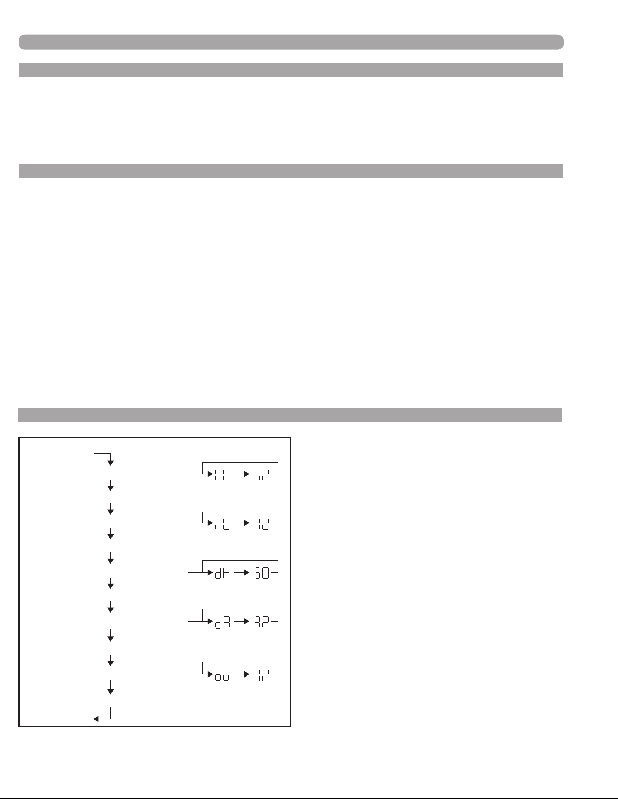
SERVICING
F. TO TURN OFF GAS TO THE APPLIANCE
1) Set the thermostat to lowest setting.
2) Turn off power switch on front of unit.
3) Turn off all electric power to the appliance if service is to be performed.
4) Turn gas shutoff valve clockwise to “off.” Handle will be horizontal. Do not force.
G. PUMP & WIRING CONTROL
The FMT 914 control board has an on-board relay for controlling the circulating pump. On a call for heat, the
pump will start, allowing the water ow switch circuit to be made and the pre-start diagnostic to continue. After
the call for heat has been satised, the pump will continue to run for the factory programmed period of time
(3 minutes) and then shut off. For water heating applications an external temperature sensor must be mounted in
the water storage tank or the pump must be wired to run continuously. For heating applications the call for heat
must come from an external source (room thermostat etc.). In both applications if a continuous pump operation
is desired, it may be specially factory programmed for that or the pump should be wired directly to an external
power supply.
The only restriction is the amount of pump electrical load that can be connected. The maximum wattage externally
connected loads can draw is 650 watts. All standard pumps as supplied by Hamilton Engineering draw 550 watts
or less.
The EVO control system has the ability to control up to three (3) pumps, or two (2) pumps and a diverting valve.
For details see EVO Congurations Manual (LIT91110) or contact Hamilton Engineering at 800.968.5530.
H. TEMPERATURE SENSOR READING INSTRUCTIONS
(FIGURE 7-1) TEMPERATURE SENSOR
Reset Button
Show Flow (Outlet) Temp.
Reset Button
Show Return (Inlet) Temp.
Reset Button
Show Indirect (Tank) Temp.
Reset Button
Show Cascade Temp.
Reset Button
(Direct heated storage tank
or common loop sensor)
READING INSTRUCTIONS
Show Outside Temp.
Reset Button
Normal Display
34000 Autry Street, Livonia, MI 48150 | 800.968.5530 | Fax 734.419.0209 | www.hamiltonengineering.com | LIT91127US REV 5/2018
Page 46
Page 47
I. EVO SENSOR RESISTANCE TABLE
SERVICING
(TABLE 7-7) EVO SENSOR
RESISTANCE TABLE
TEMPERATURE
(OF)
32 32550 0 32550
41 25340 5 25340
50 19870 10 19870
59 15700 15 15700
68 12490 20 12490
77 10000 25 10000
86 8059 30 8059
95 6535 35 6535
104 5330 40 5330
113 4372 45 4372
122 3605 50 3605
131 2989 55 2989
140 2490 60 2490
149 2084 65 2084
158 1753 70 1753
167 1481 75 1481
176 1256 80 1256
185 1070 85 1070
194 915 90 915
203 786 95 786
RESISTANCE
(OHM)
TEMPERATURE
(OC)
RESISTANCE
(OHM)
PART 8. MAINTENANCE
A. MAINTENANCE PROCEDURES
All high efciency condensing appliances will require more regular maintenance (cleaning) than their non-
condensing counterparts. Failure to do so may result in damage to the appliance that is not covered under warranty.
Failure to follow all of the instructions contained in this manual may also cause premature product failure that
may not be covered under warranty.
Periodic maintenance should be performed at least once a year by a qualied service technician to ensure that
all the equipment is in safe, efcient operation. Failure to do so may eliminate warranty coverage. In the rst
year of operation, it is highly recommended that inspections of all connection points and the combustion chamber
be done at three month intervals, any signs of fouling or leaks must be thoroughly investigated immediately as
failure to do so may void warranty. Assuming no cause for excessive fouling is found, then the period of months
from initial start up that it was found that cleaning was required, shall become the required future minimum cleaning interval, but at no time should it exceed 12 months. The owner MUST make necessary arrangements with
a qualied heating contractor for proper maintenance of the heater. Installer must also inform the owner that
the lack of proper care and maintenance of the heater may result in a hazardous condition and lack of warranty
coverage. The installer should discuss the contents of the User’s Information Manual with the owner.
34000 Autry Street, Livonia, MI 48150 | 800.968.5530 | Fax 734.419.0209 | www.hamiltonengineering.com | LIT91127US REV 5/2018
Page 47
Page 48
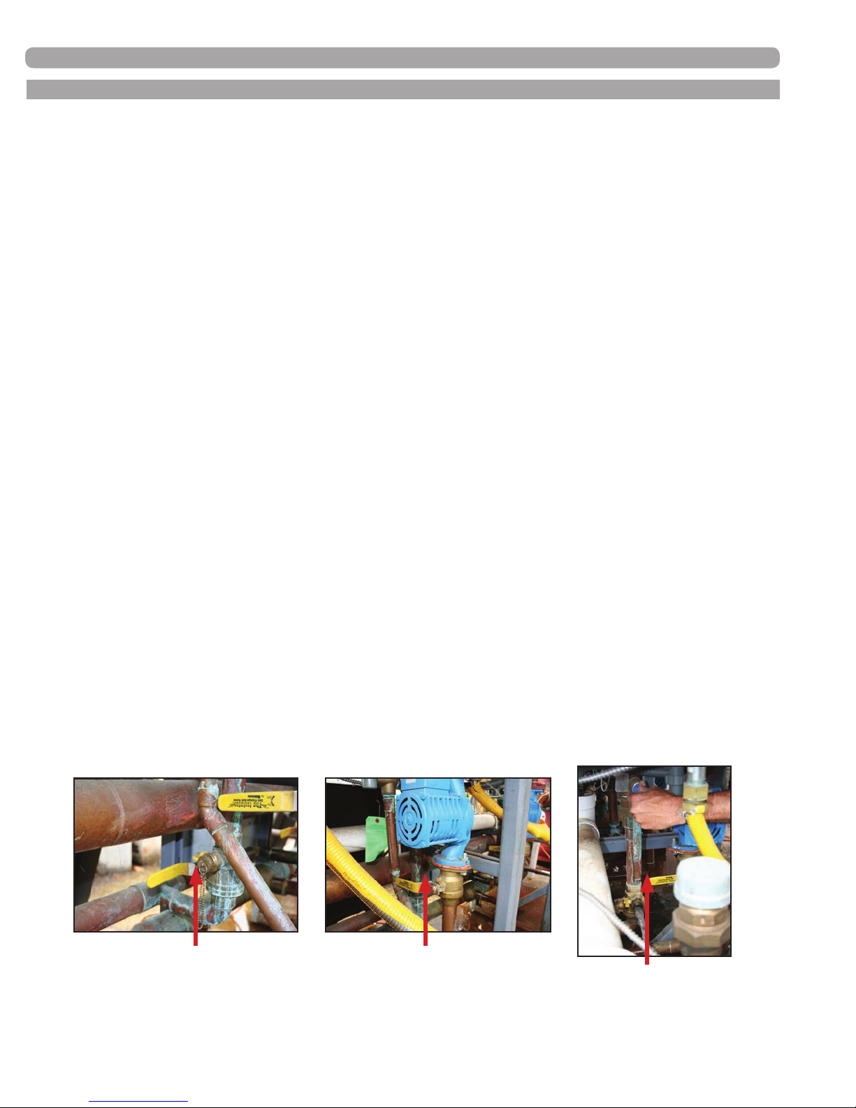
MAINTENANCE
B. ANNUAL INSPECTION (See LIT91179 Maintenance Checklist for required tools and materials)
An inspection should cover, at a minimum, the following areas:
• Download and review operating hour data and fault history
• Inspect all ttings, controls and connections for leaks, damage, or fouling
• Fire side:
Heat exchanger
Burner and ignitor
Burner door and rear wall insulation
• Drain system components:
Hoses & clamps
Trap assembly
Condensate neutralizer
• Test all safeties and operating controls
• Water side temperature rise (∆T) test
DATA DOWNLOAD
Always retrieve fault history and power on hours from the control board rst, using your laptop or PDA and the
SIT cable and software. Be sure to use the proper version software and communication cable, then save the
le and name appropriately for future reference. Should the servicing contractor not have the proper software,
cables, and training to do this, have them contact the factory or their local distributor.
INSPECTION AND CLEANING (photos illustrating each step follow sets of instructions)
Caution: Before removing the door of the appliance, switch off the electrical power supply to it.
• Remove the front cover and check the sensors, ow switch, all pipes, lines and connections,
and the heat exchanger (top, bottom) for traces of water and water leakage.
• Inspect the top of the casing and/or the top of the appliance for water leakage or traces of
water from the air supply pipe or the air vent (if applicable).
• Inspect the ow switch; the appliance must rst be drained by closing the inlet and outlet valves on
each appliance. Then, by opening the drain on the ball valve and the relief valve, the appliance will drain.
Isolation and drain
valve appliance outlet
34000 Autry Street, Livonia, MI 48150 | 800.968.5530 | Fax 734.419.0209 | www.hamiltonengineering.com | LIT91127US REV 5/2018
Isolation valve for pump
& appliance outlet
Page 48
Relief valve - check operation
and open to drain unit
Page 49
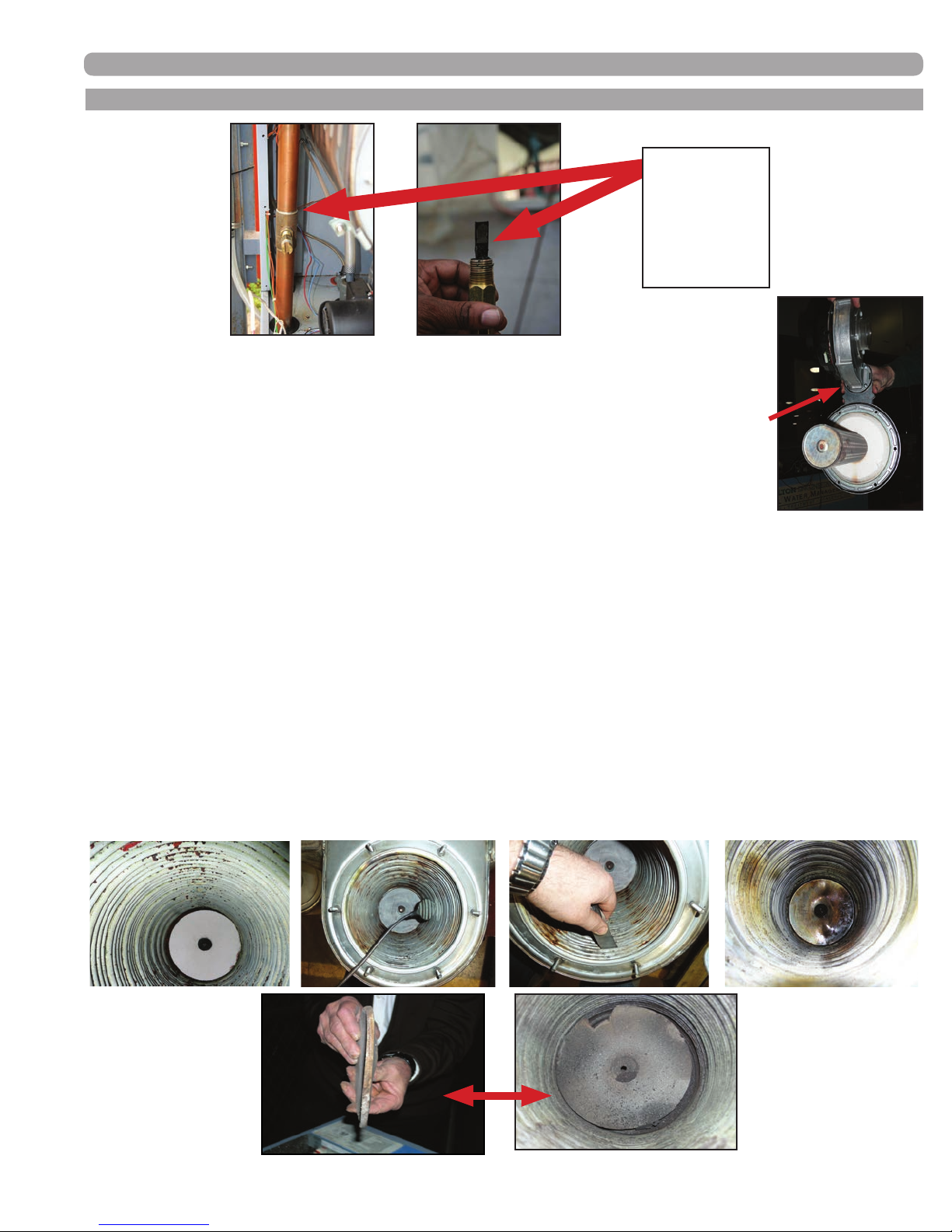
MAINTENANCE
B. ANNUAL INSPECTION CONT.
FLOW
SWITCH:
Check paddle for
fouling and free
movement by
spring!
• Dismantle the burner unit: remove the (6) 6mm nuts (with a 10mm socket), the ignition
cable, the power and speed control plugs, and the ground wire from the fan, and
remove the burner/fan unit from the heat exchanger and cabinet.
• After the burner door is removed, it should be thoroughly inspected
before being put back into service. There are two gaskets on the
burner door; the rst is the inner rope gasket, which is permanently afxed to the burner
door. If this gasket is completely compressed (having no sealing ability), the door must
be replaced. The second gasket is on the perimeter and is made of rubber; this gasket
is easily replaced, and comes as a standard part of a maintenance kit (and should always be replaced
during the annual maintenance procedure. Note: Over-tightening the M6 nuts may cause the threaded
rods on the front of the heat exchanger to break! If excess resistance is encountered when installing
a M6 nut, discard that nut and use one of the spares shipped with the unit. The maximum torque for
assembling a burner door nut is 3.7 ft-lb or 44.4 in-lb. Use a torque wrench suitable for this torque
range to tighten the nuts.
• Remove and inspect the rear berboard. If any resistance is encountered with the removal of the screw
securing the berboard in place, do not exert undo force; break the berboard out to provide access to the
screw. Apply penetrating oil to the screw, let it sit, then remove. See photos below for details. Replace only
after cleaning procedure. Use a new berboard if moisture has fouled it or if there is any physical damage
preventing it from protecting the rear wall, such as cracks or warping. Warped berboards will allow the back
wall to overheat, this could lead to a breach of the back wall. This will also cause a loss of efciency and a
rise in stack temperature. Note: Failure to replace front and rear berboard when damaged may result
in irreparable damage to the appliance!
Complete burner,
door & fan assembly
removed for inspection
34000 Autry Street, Livonia, MI 48150 | 800.968.5530 | Fax 734.419.0209 | www.hamiltonengineering.com | LIT91127US REV 5/2018
Both of
these
must be
replaced!
Page 49
Page 50
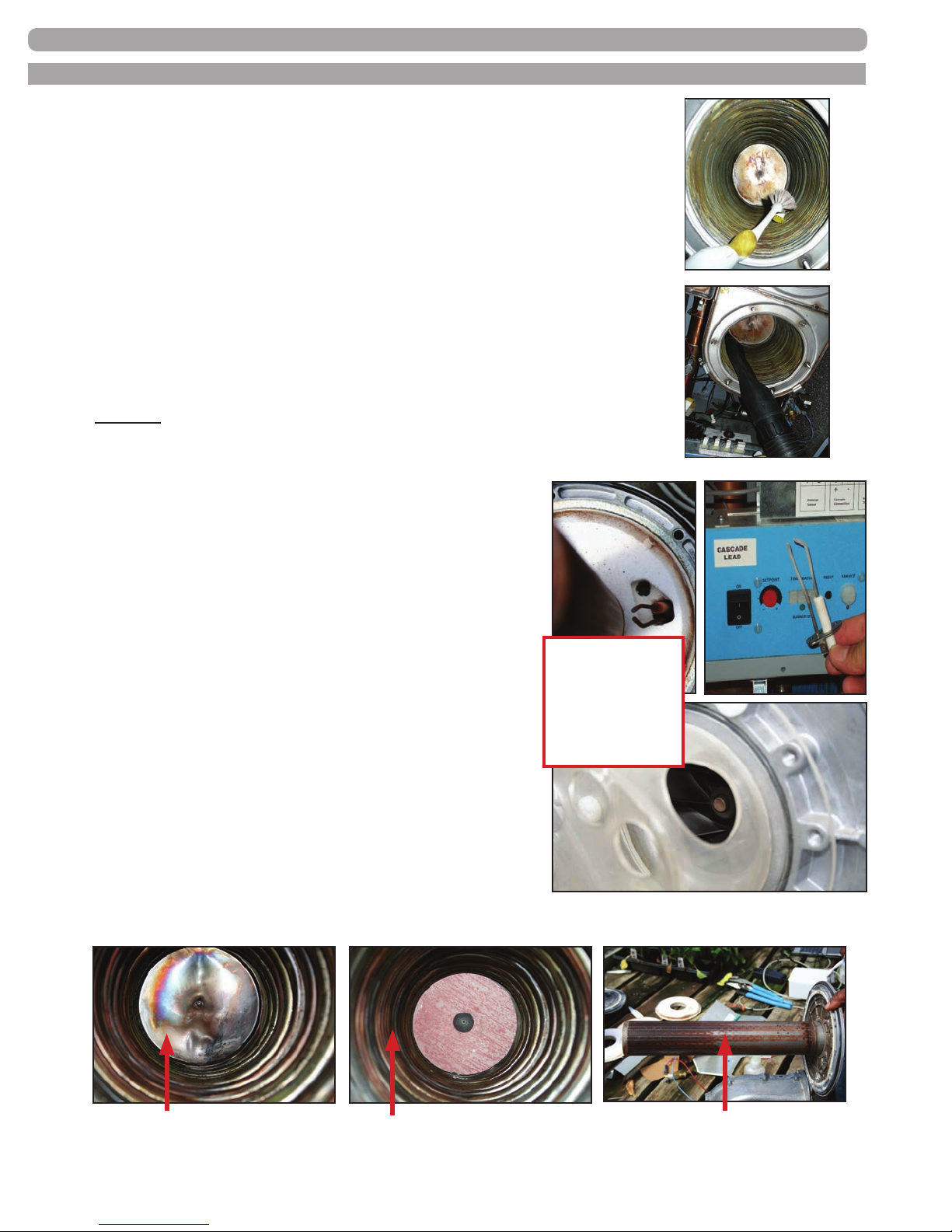
MAINTENANCE
B. ANNUAL INSPECTION CONT.
• Check the re side of the heat exchanger: only clean loose residue from
the heat exchanger coil, use a vacuum cleaner and nylon brush, and do
not push the residue between the openings of the coils if at all possible,
as this may impede the ow of the products of combustion.
• Use inspection mirror to check all heat passage spaces between coils, and
using a short, thin putty knife or strip of stainless steel, remove all
debris. These passages MUST be free and clear for proper heat transfer
to occur. Rinse well all loose debris that was pushed down to the bottom
of the condensate collection tray.
• It is recommended to only use clear water to rinse any remaining residue
away—the water will automatically ow to the condensate drain point.
• If surface or coil gap fouling still exists after the above measures have
been taken, the heat exchanger requires additional cleaning. Use a
non-acid based cleaning solution, such as Fernox F3, to thoroughly soak
the remaining residue. Brush clean and then completely rinse all residue
and cleaning solution down the condensate drain assembly. Repeat if
necessary.
(See complete cleaning instructions on page 53–55)
• Check the distance from the electrode to the burner; there
should be a 3/8" gap in between the two. If the existing
electrode pins must be adjusted for proper gap, caution
must be exercised, as they will likely be brittle from exposure
to the ame; try to bend them as close to the burner door
insulation as possible using two pair of pliers; one to support
the rod, and one to bend with. New electrodes will be less
susceptible to breakage during adjustment. The metal surface
of the electrodes should also be carefully cleaned with
emery cloth.
Burner door refractory
must sit rmly against
burner door and must
not have any cracks,
water damage, or gouges.
If any of these exist, it
MUST be replaced.
Note: Do not make any adjustments or cleaning with
the electrode still mounted to the burner door, as
damage to refractory may result!
• Dismantle the air gas mixing plate or chamber on the suction
side of the fan and check for fouling. If required, clean the
fan blade wheel and the air gas mixing box.
• Reassemble the burner chamber, making sure there is no moisture on any of the reside components.
Cleaned heat exchanger -
prior to rear wall installation
34000 Autry Street, Livonia, MI 48150 | 800.968.5530 | Fax 734.419.0209 | www.hamiltonengineering.com | LIT91127US REV 5/2018
Cleaned heat exchanger -
after rear wall installation
Page 50
Burner & door assembly -
prior to berboard installation
Page 51
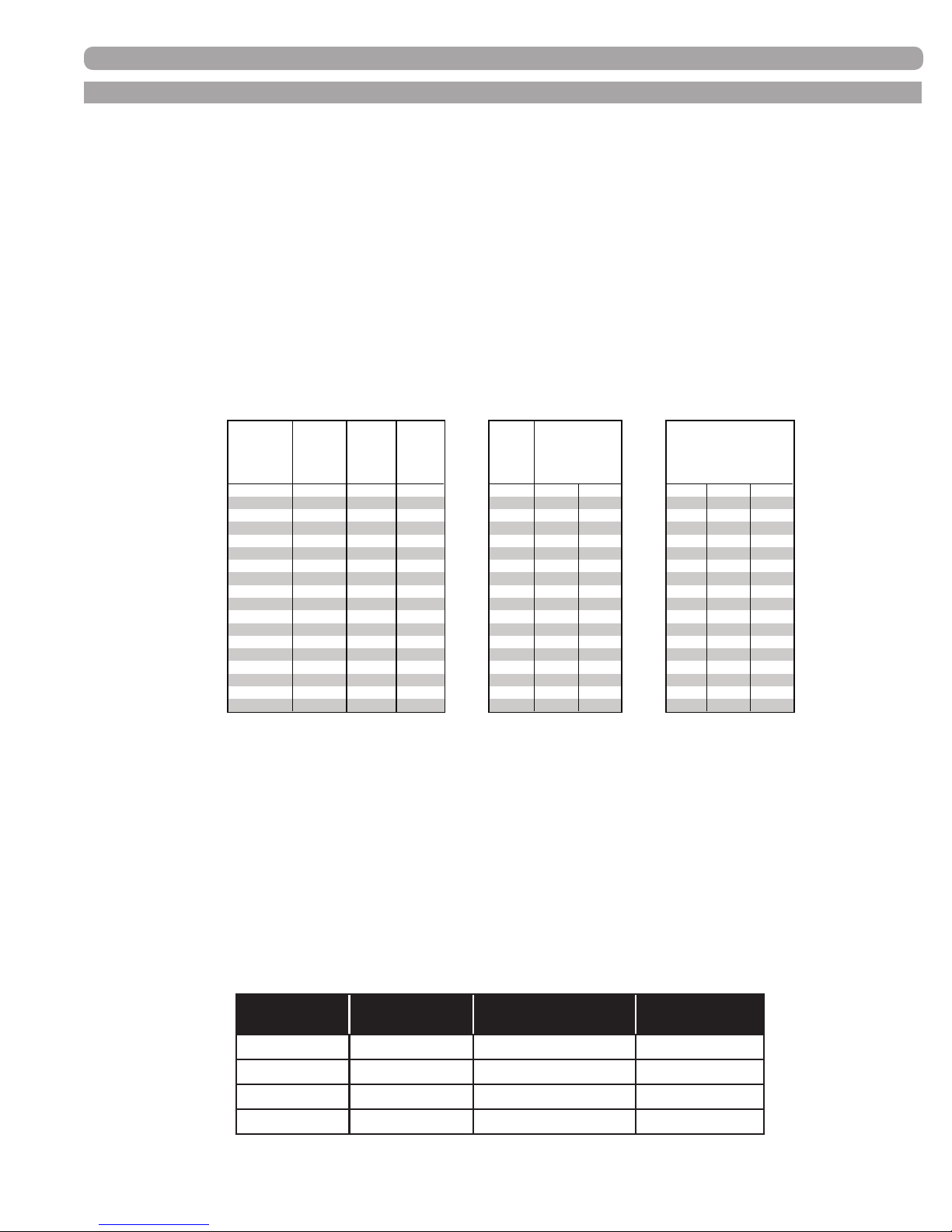
MAINTENANCE
Hamilton EVO Products
Flow and Pressure Drop (GPM Feet of Head)
Design
HW 79 - 129 (.8) HW 179 - 199.1 (.8)
HW 299 HW 399 HW 599 HW 1499 HW 1999
Flow Rate
GPM Head GPM Head GPM Head GPM Head GPM Head GPM Head GPM Head
2.2 1.8 3.5 2.1 6.6 3.4 13.2 4.8 22.0 5.9 52.8 6.3 70.4 6.2
3.3 4.6 4.4 3.9 8.8 6.0 15.4 6.5 24.2 7.2 57.2 7.4 76.3 7.4
Hydronic 4.4 (4) 7.9 6.6 (5) 7.9 11.0 9.3 17.6 8.5 26.4 9.4 61.6 8.6 82.2 8.6
5.3 11.6 7.7 12.5 13.2 13.4 19.8 10.8 30.8 11.6 70.5 11.2 99.8 12.6
6.2 15.4 8.8 15.2 15.4 18.3 22.0 13.4 35.2 15.2 79.3 14.2 111. 5 15.8
DHW - direct 6.6 17.7 9.9 17.7 16.5 21.1 26.4 19.2 39.6 21.3 92.5 19.3 123.3 19.3
7.7 24.1 11 21.5 17.6 23.9 30.8 26.2 41.8 21.4 96.9 21.2 129.2 21.2
8.8 31.5 12.1 29.5 19.8 30.2 33.0 30.1 44.0 23.7 101.3 23.1 135.0 23.1
Minimum
Hydronic
Minimum
efficiency
°F °C
T
efficiency
°F °C
B. ANNUAL INSPECTION CONT.
TESTING
The following steps require the power supply be turned back on; extreme caution must be exercised
when performing service with the power supply on and the door off.
• When turning the appliance back on, listen for signicant noises from the fan and pump. Also, inspect
for leaks at the pump connections.
• Press the reset button from the home screen to access the sensor readings, and record each reading,
making sure that all sensors and thermometers are reading the same, with the heat off.
• Fire the appliance on maximum output for 5 minutes, in order to check the ∆T from the inlet sensor to
the outlet sensor.
- If the ∆T reading is out of design range by more than 10% or there is an E6 error on the
display, refer to coil cleaning instructions below. Record ∆T to track any increases from one
year to the next.
∆P at
Flow
Model
HWH 79 80,000 2.23 3.3 1" 34.6 19.2 1"
HWD 79 80,000 23.5 13.1
HWH 129 136,300 3.64 3.5 1" 58.9 32.7 1"
HWD 129 136,300 40.1 22.2
HWH 179 186,600 5.06 3.3 1" 53.7 29.8 1"
HWD 179 186,600 36.6 20.3
HWH 199.1 199,999 5.63 3.5 1" 57.6 32.0 1"
HWD 199.1 199,999 39.2 21.8
HWH 299 300,000 8.45 4.9 1.5" 51.8 28.8 1.5"
HWD 299 300,000 35.3 19.6
HWH 399 399,999 11.31 3.5 1.5" 43.2 24.0 2"
HWD 399 399,999 29.4 16.3
HWH 599 630,000 17.74 4.9 1.5" 45.3 25.2 2"
HWD 599 630,000 30.9 17.1
HWH 1499 1,500,000 42.13 5.2 2.5" 46.3 25.7 2.5"
HWD 1499 1,500,000 31.5 17.5
HWH 1999 1,999,999 58.45 5.2 2.5" 46.3 25.7 2.5"
HWD 1999 1,999,999 31.5 17.5
BTU/hr.
Input
Flow
Rate - ft.
of head
Hydroni
c Pipe
Size
Design ∆T
Hydronic
@ 95%
DHW
Pipe
Size
Design ∆
DHW @ 97%
• Fire the appliance on maximum output, and measure and adjust the CO
• Fire the appliance on minimum output, and measure and adjust the CO
• If there are an unusual number of F5 or F6 faults or if combustion is off signicantly, gas supply
pressure must be veried at static (no load) and full building load conditions.
• See Table 3-3, Page 17 for specic settings.
• Inspect intake and exhaust screens at the termination point for signs of contamination (i.e. leaves, twigs, etc).
• A differential pressure (∆P) reading should be taken across the exhaust and inlet air connection points
of each appliance to conrm that it is below the maximum shown below.
NOTE: The inlet air pressure should be negative.
MODEL
HW79 < .4" wc HW299 < .7" wc
HW129 < .6" wc HW399 < 1" wc
HW179 < .96" wc HW599 < .86" wc
HW199.1 < .68" wc HWH 1499-1999 < .8" wc
34000 Autry Street, Livonia, MI 48150 | 800.968.5530 | Fax 734.419.0209 | www.hamiltonengineering.com | LIT91127US REV 5/2018
percentage as required.
AIR PRESSURE
(∆P)
MODEL
2
percentage as required.
2
AIR PRESSURE
(∆P)
Page 51
Page 52
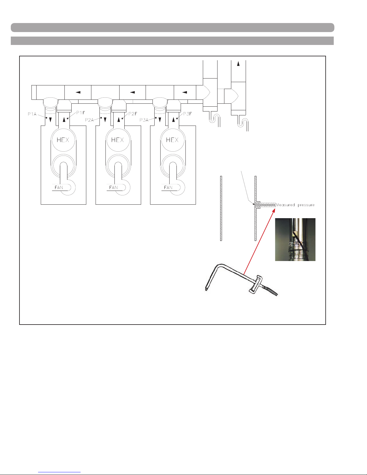
B. ANNUAL INSPECTION CONT.
MAINTENANCE
Try to keep the measuring hose at with
the inner wall of the pipe. Use a small
opening to insure you are measuring
static pressure and not velocity pressure
P (1, 2, 3) A
These will be negative pressures relative to atmosphere
P (1, 2, 3) F
These will be positive pressures relative to atmosphere
Example
P1A = -0.32” wc
P1F = 0.4” wc
Then the total pressure drop is:
∆P total = -(P1A) + P1F = -0.32 + 0.4 = 0.72” wc
Calculations are done with:
• All boilers at high re
• Water temperature 160/180ºF (gives the hottest ue gasses)
• All readings must be taken with boiler front cover installed
Doing the measurements under these conditions will give the most accurate results. There may be minor differences between appliances.
Use of a static pressure
tip for measurement is
also recommended
• A pH test must be performed at the exit point of the condensate neutralizer with litmus paper to test for
acidity. pH level should be within 6.6–7.0. If the pH is less than 6.6, replace neutralizing medium.
• Checking the minimum and maximum settings on the display must be performed as a nal check.
• All ndings and concerns should be discussed with the appliance owner after the inspection is complete.
34000 Autry Street, Livonia, MI 48150 | 800.968.5530 | Fax 734.419.0209 | www.hamiltonengineering.com | LIT91127US REV 5/2018
Page 52
Page 53
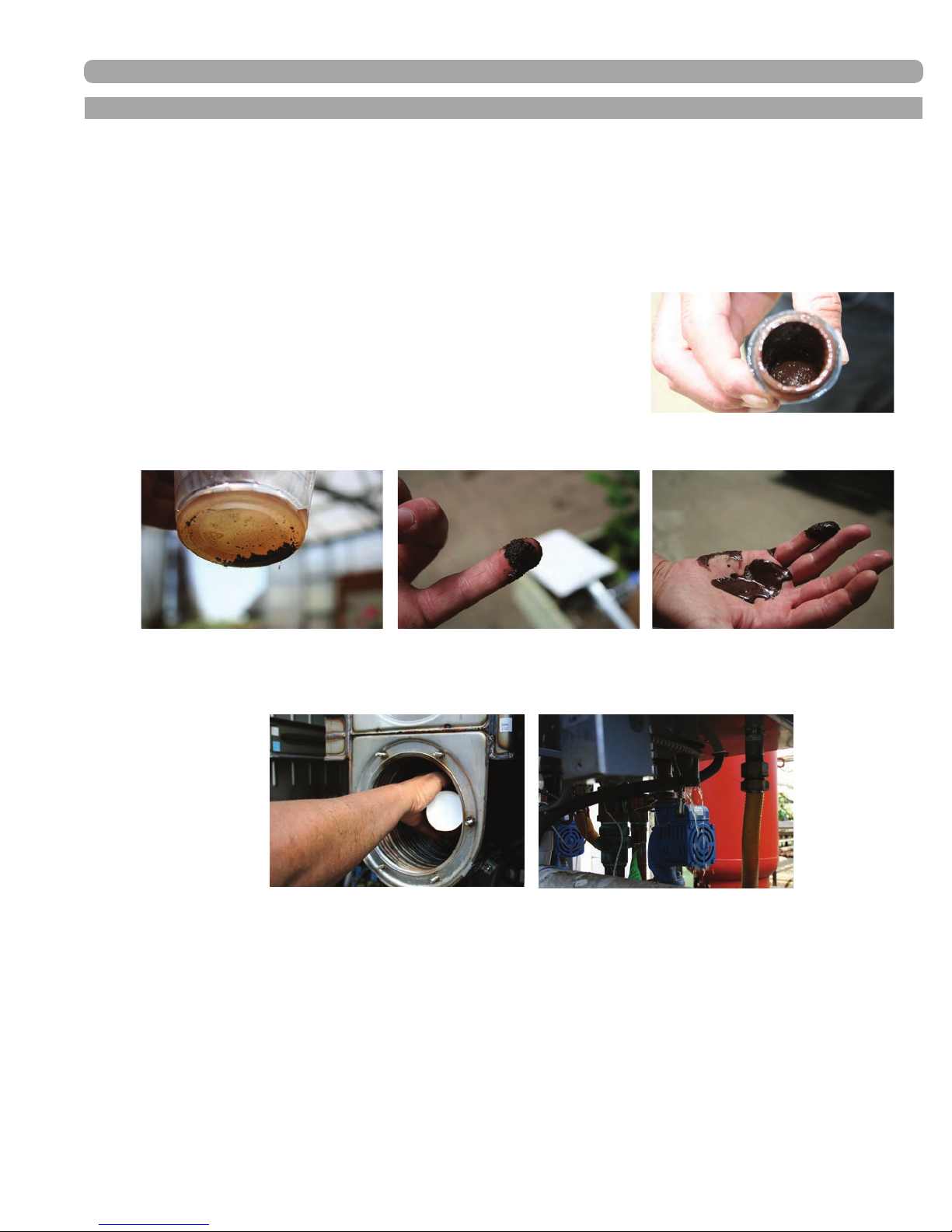
C. CONDENSATE TRAP CLEANING INSTRUCTIONS
The condensate trap and entire drain system attached to it (above the neutralizer) should be cleaned at
least once every year.
1) Turn off the power to the EVO.
2) Place a bucket under the condensate trap. Use caution when removing the clean-out cap,
as the trap is full of condensate and it may be hot.
3) Remove the condensate clean-out cap, and be sure
the bucket is under the open drain trap assembly to
catch the debris and water.
4) Rinse out the clean-out cap in a sink to remove any
dirt or buildup that may have accumulated.
5) Condensate drain assembly should now be checked for non-restricted ow throughout the
entire assembly.
6) Reinstall the clean-out cap on the condensate trap.
7) Turn on the power to the EVO.
8) Make sure the hose from the condensate trap is not submerged too far into the neutralizer,
there should be an air gap between the highest level of condensate and the outlet hose from the trap.
9) Monitor the condensate drain until ow has been established.
34000 Autry Street, Livonia, MI 48150 | 800.968.5530 | Fax 734.419.0209 | www.hamiltonengineering.com | LIT91127US REV 5/2018
Page 53
Page 54
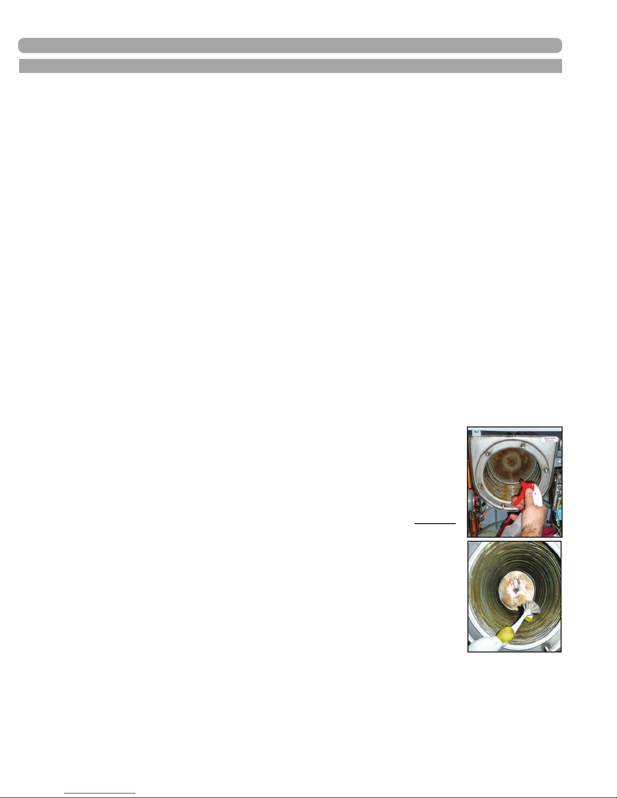
MAINTENANCE
D. COMBUSTION CHAMBER COIL CLEANING INSTRUCTIONS*
*Before beginning this procedure, you must have the following items on hand:
• Nylon brush - DO NOT use brass, stainless or steel brushes.
• Water
• Vacuum cleaner
• Fernox F3 Cleaner
• Fernox F1 Inhibitor Protector (boilers only)
• Fernox DS 40
• Towel for clean up and plastic sheeting to protect electronics.
NOTE: If electronics do get wet, DO NOT turn on power to appliance until they have been
thoroughly dried, as component failure may result.
FIRE SIDE CLEANING
1) Shut down the EVO by using the following steps:
a. Turn off the power, close the gas valve, and shut down the unit. Wait for the unit to be
cool to the touch.
b. Remove the clean-out cap and place drain bucket according to the directions above.
c. Remove the Molex plugs from the fan.
d. Remove the (6) 6mm nuts from the burner plate assembly to access the coils.
e. Pull the entire burner plate assembly towards you and remove rear target wall.
2) Vacuum rst and then use the nylon brush to scrub coils to remove any buildup. Vacuum the
debris from the coils.
3) Using a spray bottle lled with water or a hose under low pressure to avoid water
spraying on electronics (be sure to cover them to protect against water damage),
spray the coils liberally, making sure the water penetrates and funnels down
through the condensate hose. If the condensate hose is blocked, try to knock any
debris loose with a small screwdriver. Replace hose if not completely clean.
4) If surface or coil gap fouling still exists after the above measures have
been taken, the heat exchanger requires additional cleaning. Use a non-acid
based cleaning solution, such as Fernox F3, to thoroughly soak the remaining
residue. Brush clean and then completely rinse all residue and cleaning solution
down the condensate drain assembly. It may take several applications of the F3,
followed by a rinsing, to completely clean the coil surfaces. Use a spray bottle for
each (F3 and clear water). Repeat if necessary.
5) Be sure that water is owing freely through the bottom casing of the heat
exchanger and the drain is not plugged. At this point, the EVO should be ready to
power back up.
6) Before powering up the EVO follow the steps below:
a. Re-install the burner assembly and rear target wall (berboard insulation)
b. Replace the (6) 6mm nuts to the burner plate, following appropriate tightening pattern and torque.
c. Re-connect the Molex plugs.
d. Re-set system thermostats.
e. Replace the clean-out cap.
f. Turn the EVO back on** and monitor the condensate drain until ow has been established.
g. Re-connect the condensate hose to the outside connection.
34000 Autry Street, Livonia, MI 48150 | 800.968.5530 | Fax 734.419.0209 | www.hamiltonengineering.com | LIT91127US REV 5/2018
Page 54
Page 55

MAINTENANCE
D. COMBUSTION CHAMBER COIL CLEANING INSTRUCTIONS*
WATER SIDE CLEANING (de-scaling kit is required for this process, please consult factory)
1) Shut down the EVO and clean by using the following steps for heaters:
a. Turn off the power, close the gas valve, and shut down the unit. Wait for the unit to be
cool to the touch.
b. For water heaters, close both inlet and outlet water valves to isolate the appliance.
c. Open the drain valve to let out all the water from the appliance, and circulate Fernox DS 40
Cleaner in reverse of normal ow, to ush out any build up that may have occurred in the
coils. Note: Fernox DS 40 is a heat activated de-scaling solution. It must be heated
to 160º–180ºF to clean efciently. Follow Fernox instructions to ensure a fully clean
heat exchanger.
d. Flush with water to eliminate any of Fernox DS 40 Cleaner that may have been left behind.
e. Close the drain valve and open the inlet and outlet water valves to put the appliance back online.
2) Shut down the EVO and clean by using the following steps for boilers:
a. Turn off the power, close the gas valve, and shut down the unit. Wait for the unit to be
cool to the touch
b. At the chemical injection point rst add the appropriate number of bottles of Fernox DS 40
Cleaner to the system, based on total system water volume. Follow the cleaning instructions
on the bottle.
c. Open the drain valve to let out all the water from the appliance, and circulate Fernox DS 40
Cleaner in reverse of normal ow, to ush out any build up that may have occurred in the
coils. Note: Fernox DS 40 is a heat activated de-scaling solution. It must be heated
to 160º–180ºF to clean efciently. Follow Fernox instructions to ensure a fully clean
heat exchanger.
d. Flush the system of all the Fernox DS 40.
e. After the system has been ushed, add the Fernox F1 Inhibitor Protector (for closed-loop
boiler applications only) to the system at the chemical injection point and leave in the system.
One bottle of Fernox F1 treats approximately 26 gallons of water. Please follow instructions
on the bottle for specic mixing ratios.
Detailed instructions on Water Side Cleaning can be found in LIT91195 Water Side
Cleaning Procedure, available on our website.
**NOTE: When ring up the boiler for the rst few times you may experience some uttering
of the gas burner that may result in a ame lockout. This is normal and will require you to
re-cycle the unit until this clears up. This is caused by water still present in the combustion
chamber.
After all cleaning has been done, it is recommended that a combustion analysis and testing,
as shown on page 51, be completed. See LIT91111 (Start-Up Checklist) & LIT91133 (Cascade
Start-Up Procedures) for details.
34000 Autry Street, Livonia, MI 48150 | 800.968.5530 | Fax 734.419.0209 | www.hamiltonengineering.com | LIT91127US REV 5/2018
Page 55
Page 56
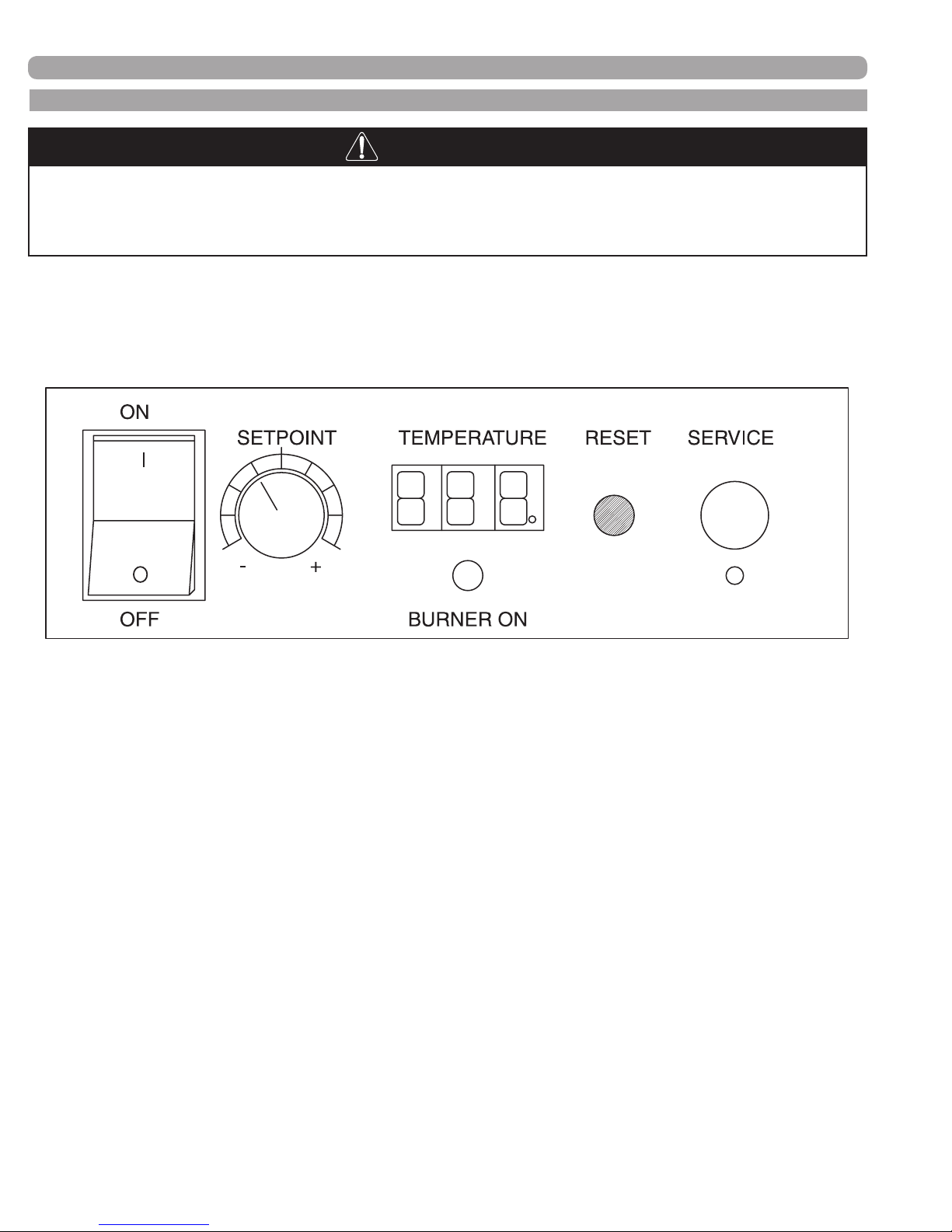
E. EVO CONTROLS
DANGER
It is extremely important that you check for leaks when reconnecting the gas
valve and make sure the exhaust vent is no longer blocked. Failure to do so may
result in severe personal injury or death.
The following components are found on the control panel on the front of the appliance.
(FIGURE 8-3) EVO CONTROL PANEL
Looking at the controls on the front of the appliance,
1) POWER on/off switch
2) SETPOINT knob, temperature control (and fan speed control knob during service mode)
3) TEMPERATURE setpoint display
a. Temperature in °F, corresponding to the SETPOINT knob
b. Display will always read temperature setpoint unless there is a fault code displayed.
c. Cascade indicator light, found in the lower right hand corner of the Temperature display.
This dot will be ashing when this appliance is part of a properly-connected, commonly-
controlled group of EVO products and reading temperature sensors.
d. Display code, not ashing indicates a Soft Lockout
e. When this display is ashing a code, the appliance is in a Hard Lockout and the reset
must be pushed to re-start the appliance.
4) Green indicating light labeled BURNER ON; when this is light is on, the burner is ring.
5) RESET button, used as described in 3e above, as well as to view sensors and set altitude
(see pages 46 & 64 respectively for details).
6) SERVICE port, used for connecting a computer to the appliance to download the service fault
history, as well as factory setting of control board parameters. There is a service button located
just below the service port that must be pressed with a pointed object to get to the service mode.
34000 Autry Street, Livonia, MI 48150 | 800.968.5530 | Fax 734.419.0209 | www.hamiltonengineering.com | LIT91127US REV 5/2018
Page 56
Page 57

MAINTENANCE
F. COIL ANTI-SCALING PREVENTION FEATURE
The EVO controller (FMT 914) contains sophisticated software that enables it to monitor the rate of temperature
rise through the heat exchanger. By doing this, it greatly reduces the possibility of heat exchanger failure due
to scaling or fouling. A set of parameters are programmed in at the factory, to provide a design temperature rise
(∆T) setting on each size unit that is xed. The Anti-Scale is based on an increase over the design ∆T through
the heat exchanger. This Anti-Scale is determined using the inlet and outlet sensors, even if a tank thermistor
is being used. If the Anti-Scale setting is reached, the unit will display A8, shut down and not re-re until it has
cooled. After the rst three times this condition is reached in the FMT 914 reset life cycle (reset life cycle is the
time between factory service history downloads), the FMT 914 control will go into hard Lockout, display E6, and
have to be manually reset. After it has been reset, it will re again, but at a maximum of 50% of rated input in
an attempt to prevent further damage but still provide some hot water. Once the heat exchanger has been acid
cleaned contact the factory for instructions on resetting the unit for full rated BTU input.
Typical causes for repeated E6 indications at start up are air trapped in the heat exchanger (be sure air vent cap
is loose) or contaminates lodging in the piping or heat exchanger during installation, both of these causes can
generally be cleared by isolating the hot water system and ushing water at full city pressure through the drain
valve or relief valve on the heater outlet.
Please note: Scale monitoring feature only available on HWD (water heater) models.
34000 Autry Street, Livonia, MI 48150 | 800.968.5530 | Fax 734.419.0209 | www.hamiltonengineering.com | LIT91127US REV 5/2018
Page 57
Page 58
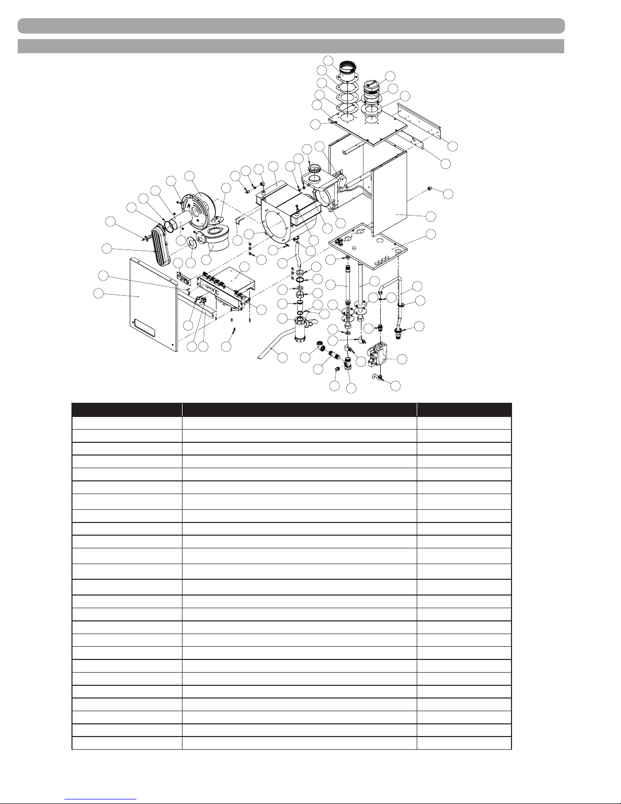
G. EVO HW 79-199.1 PARTS BREAKDOWN
MAINTENANCE
71
69
70
69
67
68
72
73
74
64
29
28
26
23
24
8
14
6
5
4
2
3
13
1
7
9
17
15
12
16
25
11
27
22
10
18
19
76
31
30
75
21
33
36
38
20
40
42
24
32
44
34
35
45
37
47
39
41
49
50
54
53
52
46
48
59
50
51
55
58
56
57
60
61
66
65
63
62
43
NO. ON DRAWING PART DESCRIPTION PART NUMBER
1 Panel Front Door Assembly HW79-199.1 JKD 94100
2 Pilot Spark Electrode Assembly HW79-599 Knurled PLT 94318
3 Burner Air/Gas Mixer Inlet HW79-399 GAS 74802
4 Gasket for Electrode HW79-599
5 Gasket Down Tube/Burner HW79-599 GKT 74029
6 Burner HW179-199.1 - 70mm x 137mm BNR 74030
Burner HW79-129 - 70mm x 105mm
7 Burner Door w/rope and EPDM gasket HW79-599 BNR 74702
8 Burner Door Insulation HW79-599 FIB 74007
9 Gasket Gas/Air Inlet Pipe & Fan-38mm, HW129 GKT 74053
Gasket Gas/Air Inlet pipe & fan-42mm, HW199.1
Gasket Gas/Air Inlet pipe & fan HW179, 299-399
Gasket Gas/Air Inlet pipe & fan-HW79
10 Fan RG 128e HW79-199.1 FAN 74313
11 Venturi HW79-199.1 FAN 74059
12 Cover Protective Assembly HW79-199.1 JKC 94100
13 Pan Head Screw 10-16 x 1/2 Thread Forming PPH 10-16X1/2 Z
14 Limit Temperature Switch Burner Door HW79-599 HLC 74700
15 Cap Front Panel Bushing & Program Port CAP 74000
16 On/Off Switch HW79-1999 SWT 74144
17 Display Assembly HW79-599 RLY 74061
18 Electronics/Display Drawer Assembly, HW79-199.1 PAN 94100
19 Nylon M3x19mm Female Threaded Hex Standoff HWR 74209
20 Control Board HW79-1999 RLY 74062
21 U Clips, Wrapper HW79-199.1, Side Panel HW299-599 HWR 74204
(only needed on PLT 74318) GKT 74018
BNR 74031
GKT 74058
GKT 74049
CF
34000 Autry Street, Livonia, MI 48150 | 800.968.5530 | Fax 734.419.0209 | www.hamiltonengineering.com | LIT91127US REV 5/2018
Page 58
Page 59
G. EVO HW 79-199.1 PARTS BREAKDOWN (CONTINUED)
NO. ON DRAWING PART DESCRIPTION PART NUMBER
22 Fork Clip HW79-199.1 Arms MSC 74020
23 Elbow 1/8"in x 1/8" out for HW79-199.1 High Limit MSC 74024
24 Bushing SS Hi Limit HW79-199.1 G1/8" MSC 74133
25 Hi Limit HW79-1999, 210˚F HLC 74274
Hi Limit HW79-1999, 198˚F HLC 74066
26 Heat Exchanger HW79-129 - ASME H-Stamp HEX 74161
Heat Exchanger HW179-199.1 - ASME H-Stamp HEX 74117
27 Hex Hold Down Clip HW79-199.1 BKT 74101
28 Gasket Flue Bushing HW79-199.1 GKT 74004
29 Flue Outlet Gasket (60 DIA) HW9-199.1 GKT 74301
30 Gasket for ue outlet pipe, HW79-199.1 GKT 74300
31 Flue Outlet Pipe, 7HW9-199.1 ARM 74202
32 Clamp Spring Double Wire 24mm HWR 74100
33 Lower Condensate Drain Hose Assembly HW79-199.1 CDK 94200
34 Reducing Ring HW79-199.1 CDK 74075
35 Sealing Gasket HW79-199.1 Condensate GKT 74037
36 Gasket Siphon HW79-199.1 5/8ID Hose GKT 74132
37 Nut 1.25 HW79-199.1 CDK 74133
38 Tube 1.25 HW79-199.1 CDK 74134
39 Washer Slip Joint 1.25 HW79-199.1 CDK 74135
40 Condensate Drain Assembly. HW79-199.1 CDK 94114
41 Adapter 21mm Air Inlet Hose CDK 74074
42 Drain Hose Condensate Trap to Condensate Manifold CDK 74038 B
43 Bottom Plate HW79-129 - Sheet Metal Only JKB 74100
Bottom Plate HW79-129 - Complete Bottom Assembly JKB 94100
Bottom Plate HW179-199.1 - Sheet Metal Only JKB 74101
Bottom Plate HW179-199.1 - Complete Bottom Assembly JKB 94101
44 O-ring SS HW79-199.1 Arms GKT 74131
45 Arm Outlet Assembly HW79-199.1 ARM 74129 O
46 Arm Inlet Assembly HW79-199.1 ARM 74129 I
47 Switch Flow V-10/at paddle, HW79-199.1 WTR 62056
48 Gasket Outer for Fast connect arms HW79-199.1 GKT 74064
49 EPDM Gasket for Arm HW79-199.1 GKT 74129 C
50 Sensor Inlet/Outlet NTC for HW79-199.1 TST 74395
51 Tee Br Outlet Arm 1" HW79-199.1 Includes items 52, 53 & 54 ARM 94100
52 Plug Brass - 1/2" BRS 95103
53 Nipple Brass - 3/4" X 3" BRS 97079
54 Elbow Brass 90˚ 3/4" BRS 93205
55 Tube Gas HW79-199.1 Inlet GAS 94001
56 Hose Clamp 7/16 to 25/32" HWR 74205
57 Grommet Air Vent Tube GKT 74045
58 Gasket nylon for HW79-199.1 gas valve GKT 74055
MAINTENANCE
34000 Autry Street, Livonia, MI 48150 | 800.968.5530 | Fax 734.419.0209 | www.hamiltonengineering.com | LIT91127US REV 5/2018
Page 59
Page 60
G. EVO HW 79-199.1 PARTS BREAKDOWN (CONTINUED)
NO. ON DRAWING PART DESCRIPTION PART NUMBER
59 Nipple Ftg BSPT Male x NPT Male 1/2" HW79-599 BRS 74100
60 Valve Gas HW79-599
61 Tube Gas HW79-129 Outlet
Tube Gas HW179-199.1 Outlet
62 Cabinet HW79-199.1 - Sheet Metal Only
Cabinet HW79-129 - Complete w/insulation & Brackets
Cabinet HW179-199.1 - Complete w/insulation & Brackets
63 Plastic feet for HW79-199.1
64 Switch P Condensate HW79-599
65 Hanger Bracket Spacer HW79-599
66 Hanger Bracket HW79-599
67 Top Plate HW79-199.1 3+1, H-Stamp Sheet Metal Only
Top Plate HW79-199.1 3+1, H-Stamp Complete w/Intake &
Exhaust Connections
68 Front Panel Pin Guide Bushings, HW79-199.1
69 Gasket Air Inlet connection HW79-199.1
70 Flange Condensate Air Inlet with Nipple HW79-199
71 Flue Air Inlet Pipe HW79-199.1
72 Valve Non-Return HW79-199.1
73 Flue Gas Outlet Assembly HW79-199.1
74 Flange Flue Gas Outlet HW79-199.1
75 Barb Straight for Hex Condensate Drain Hose HW79-199.1
76 Bushing SS Hi Limit G1/4"-M5
Not Shown Valve Relief P 50# .75x.75
Not Shown Valve Relief P 125# .75
Not Shown Flue Gas Analyzer port plug 79-599
Not Shown Hose Condensate Air Intake/PS Drain Hose
Not Shown Bracket Pressure Switch Mount HW79-199.1
Not Shown Fuse 250V-3.15A
Not Shown Nut for Burner Door HW79-1999
Not Shown Fiberboard Back Wall, 16mm
Not Shown Kit Maintenance Heat Exchanger 16mm Knurled
MAINTENANCE
VAL 74050
GAS 94002
GAS 94003
JKR 74400
JKR 94100.1
JKR 94100
MSC 74083
PRS 74326 A
BKT 74205
BKT 74204
JKT 74100
JKT 94100
HWR 74200
GKT 74042
MSC 74017
MSC 74146
VAL 74096
VNT 94100
MSC 74136
MSC 74900
MSC 74134
RLV 10417-50
RLV 03006
GKT 74093
CDK 74001
BKT 74102
FUS 74315
FHN 74100
FIB 74902
MNT 94309A
34000 Autry Street, Livonia, MI 48150 | 800.968.5530 | Fax 734.419.0209 | www.hamiltonengineering.com | LIT91127US REV 5/2018
Page 60
Page 61
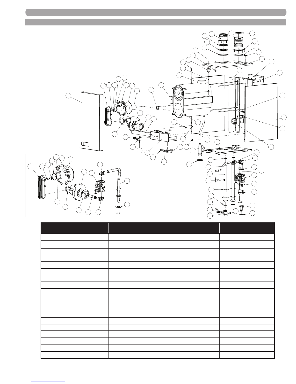
H. EVO HW 299-599 PARTS BREAKDOWN
MAINTENANCE
HW 299/399 Assembly
70
4
3
45
41 42
69
52
40
39
38
34
68
67
66
43
65
64
61
62
60
44
59
58
57
56
55
37
35
36
35
33
14
31
25
32
13
5
3 4
2
1
13
6
5
7
75
72
59
71
9
73
74 75
6
7
8
10
9
12
14
15
77
55
24
22
11
16
17
19
20
43
25
18
23
26
27
29
30
28
46
63
47
48
49
50
54
53
51
NO. ON DRAWING PART DESCRIPTION PART NUMBER
1 Panel Front Door Assembly HW299-399 JKD 94101
Panel Front Door Assembly HW599 JKD 94102
2 Burner Air/Gas Mixer Inlet HW599 BNR 74500
3 Pilot Spark Electrode Assembly HW79-599 Knurled PLT 94318
4 Gasket for Electrode HW79-599
(only needed on PLT 74318) GKT 74018
5 Gasket Down Tube/Burner HW79- 599 GKT 74029
6 Burner Door w/rope and EPDM gasket HW79-599 BNR 74702
7 Burner Door Insulation HW79-599 FIB 74007
8 Burner HW599 - 70mm x 395mm BNR 74029
9 Gasket Fan HW599 GKT 74039
Gasket Gas/Air Inlet pipe & fan HW179, 299-399
10 Fan, RG 175, HW599
GKT 74049
FAN 74070
11 Venturi HW599 FAN 74061
12 On/Off Switch HW79-1999 SWT 74144
13 Limit Temperature Switch, Burner Door HW79-599
14 Cap Front Panel Bushing & Program Port
15 Plastic stand-off for Display Panel HW79-1999
16 Plate Protection Boiler Control HW299-599
HLC 74700
CAP 74000
HWR 74203
JKC 94101
34000 Autry Street, Livonia, MI 48150 | 800.968.5530 | Fax 734.419.0209 | www.hamiltonengineering.com | LIT91127US REV 5/2018
Page 61
Page 62
H. EVO HW 299-599 PARTS BREAKDOWN (CONTINUED)
NO. ON DRAWING PART DESCRIPTION PART NUMBER
17 Electronics/Display Drawer Assembly, HW299-599 PAN 94101
18 Spacer Unthreaded, 4-40 ID x 1/4"OD x5/16" HWR 74206
19 Nylon 6-32 1/4x3/4 Female thread Hex Standoff C/F
20 Control Board HW79-1999 RLY 74062
22 Fork Clip HW599 Arms MSC 74123
Fork Clip HW299 Arms MSC 74021
Fork Clip HW399 Arms MSC 74022
23 Hold Down Heat Exchanger HW299-599 JKR 74169
24 Heat Exchanger HW299 - ASME H-Stamp HEX 74142
Heat Exchanger HW399 - ASME H stamp HEX 74129
Heat Exchanger HW599 - ASME H Stamp HEX 74130
25 Stainless Inlet/Outlet Sensor HW79-1999 TST 74287 S
26 Bushing SS Hi Limit G1/4"-M5 MSC 74134
27 Hi Limit HW79-1999, 210˚F HLC 74274
Hi Limit HW79-1999, 198˚F HLC 74066
28 Drain Hose Lower HW599 CDK 94202
Drain Hose Lower HW299-399 CDK 94201
29 Condensate Drain Assembly HW299-599 CDK 94097
30 Grommet Cabinet/Condensate Clean-out - HW299-599 GKT 74044
31 Vent Air 1/8 Automatic HW299-599 HYD 72400
32 Tube Air Vent HW299-599 MSC 74008
33 Plastic bushing Front Panel Mount HW299-599 MSC 74085
34 Plate Top HW599 - Sheet Metal Only JKT 74102
Plate Top HW299-399 - Sheet Metal Only JKT 74101
Plate Top HW599 - Complete Assembly JKT 94103
Plate Top HW299-399 - Complete Assembly JKT 94101
35 Gasket HW299-599 Air Inlet connection GKT 74041
36 Flange Condensate Air Inlet with Nipple HW599 MSC 74009
Flange Condense with Nipple HW299-399 MSC 74050
37 Air Inlet Connection HW599 MSC 74049
Air Inlet Connection HW299-399 MSC 74047
38 Grommet Air Vent Tube HW299-599 GKT 74045
39 Gasket Silicon Flue gas outlet HW599 GKT 74056
Gasket Silicon Flue gas outlet HW299-399 GKT 74081
40 Flue Gas Outlet Flange HW599 MSC 74166
Flue Gas Outlet Flange HW299-399 MSC 74118
41 Flue Gas Outlet HW599 Assembly VNT 94102
Flue Gas Outlet HW299-399 Assembly VNT 94101
MAINTENANCE
34000 Autry Street, Livonia, MI 48150 | 800.968.5530 | Fax 734.419.0209 | www.hamiltonengineering.com | LIT91127US REV 5/2018
Page 62
Page 63
H. EVO HW 299-599 PARTS BREAKDOWN (CONTINUED)
NO. ON DRAWING PART DESCRIPTION PART NUMBER
42 Valve Non-Return HW599 VAL 74098
Valve Non-Return HW299-399 VAL 74097
43 Panel Side HW299-399 Left Side JKS 94100
Panel Side HW299-399 Right Side JKS 94101
Panel Side HW599 Left Side JKS 94102
Panel Side HW599 Right Side JKS 94103
44 Arm Inlet HW599 ARM 74599 I
Arm Inlet HW399 ARM 74399 I
Arm Inlet HW299 ARM 74299 I
45 Plate Bottom HW599 - Sheet Metal Only JKB 74103
Plate Bottom HW299-399 - Sheet Metal Only JKB 74102
Plate Bottom HW599 - Complete Assembly JKB 94103
Plate Bottom HW299-399 - Complete Assembly JKB 94102
46 O-ring SS HW299 Arms GKT 74032
O-ring SS HW399 Arms GKT 74033
O-ring SS HW599 Arms GKT 74034
47 Arm Outlet HW599 ARM 74599 O
Arm Outlet HW399 ARM 74399 O
Arm Outlet HW299 ARM 74299 O
48 Switch Flow V-10/at paddle, HW299 WTR 62057
Switch Flow V-10/at paddle, HW399-599 WTR 62058
49 Gasket Outer for Fast Connect Arms HW299-599 GKT 74065
50 EPDM Gasket for Arm, HW399-599 GKT 74399 B
EPDM Gasket for Arm, HW399-599 GKT 74299 B
51 Tee Br Outlet Arm 1 1/2" HW299 Includes items 52, 53 & 54 ARM 94101
Tee Br Outlet Arm 2" HW399-599 Includes items 52, 53 & 54 ARM 94102
52 Plug Brass - 1/2" BRS 95103
53 Nipple Brass - 3/4" X 3" BRS 97079
54 Elbow Brass 90˚ 3/4" BRS 93205
55 Gasket, Gas Inlet Manifold mt. plate to cabnt HW299-599 GKT 74040
56 Manifold Gas 599 Inlet GAS 74090 A
57 Fitting 3/4" comp. x 1/2" MPT, HW599 GV Inlet GAS 74006
58 Nipple Ftg BSPT Male x NPT Male 1/2" HW79-599 BRS 74100
59 Valve Gas HW79-599 VAL 74050
MAINTENANCE
60 3/4 Straight. Flange, 0-rings & screws-VAL 74050 VAL 74259
61 Manifold Gas HW599 Outlet GAS 74091 A
62 Fitting 1" Comp. x 1" FPT, HW599 Outlet BRS 74102
34000 Autry Street, Livonia, MI 48150 | 800.968.5530 | Fax 734.419.0209 | www.hamiltonengineering.com | LIT91127US REV 5/2018
Page 63
Page 64
H. EVO HW 299-599 PARTS BREAKDOWN (CONTINUED)
NO. ON DRAWING PART DESCRIPTION PART NUMBER
63 Tube Gas HW599 Outlet GAS 94092 B
64 Switch P Condensate HW79-599 PRS 74326 A
65 Gas Valve Mount Bracket Lower HW599 BKT 74501
66 Heat Ex. Hold Down Rods HW599 25.125" Long JKR 74710
Heat Ex. Hold Down Rods HW399 17" Long JKR 74709
Heat Ex. Hold Down Rods HW299 12.812" Long JKR 74708
67 Hanger Bracket Space HW79-599 BKT 74205
68 Hanger Bracket HW79-599 BKT 74204
69 Panel Rear HW599 C/F
Panel Rear HW299-399 C/F
70 Burner Air/Gas Mixer Inlet HW79-399 GAS 74802
71 Burner HW299 - 70mm x 210mm BNR 74025 B
Burner HW399 - 70mm x 296mm BNR 74027 C
72 Fan RG 148 HW299-399 FAN 74069
73 Venturi HW299 FAN 74055
Venturi HW399 FAN 74058
74 Tube Gas HW299-399 Outlet GAS 94056
75 3/4" 90˚ Flange, O-ring, screws - VAL 74050 VAL 74258
Not Shown
Not Shown
Not Shown
Not Shown
Not Shown
Not Shown
Not Shown
Not Shown
Not Shown
Not Shown
Not Shown
Not Shown
Not Shown
Not Shown
Not Shown
Not Shown
Not Shown
Not Shown
Not Shown Hi Limit rear Wall 299-1999 HLC 74500
Valve Relief P 50# .75x.75 RLV 10417-50
Valve Relief P 125# .75 RLV 03006
Gas Valve Mount Bracket Upper HW599 C/F
O-Ring RG175 Fan HW599 ORG 74070
Flue Gas Analyzer port plug HW79-599 GKT 74093
U Clips, Wrapper 79-199.1, Side Panel HW299-599 HWR 74204
Insulation Side Panel HW599 JKR 74091
Insulation Side Panel HW299-399 JKR 74092 D
Hose Condensate Air Intake/PS Drain Hose CDK 74001
Drain Hose Condensate Trap to Condensate Manifold CDK 74038 B
Adapter 21mm Air Inlet Hose CDK 74074
Bracket Pressure Switch Mount HW299-599 BKT 74202
Insulation Front Panel HW599 JKR 74105
Insulation Front Panel HW299-399 JKR 74104
Fuse 250V-3.15A FUS 74315
Nut for Burner Door HW79-1999 FHN 74100
Fiberboard Back Wall, 16mm FIB 74117
Kit Maintenance Heat Exchanger 16mm Knurled MNT 94309
MAINTENANCE
34000 Autry Street, Livonia, MI 48150 | 800.968.5530 | Fax 734.419.0209 | www.hamiltonengineering.com | LIT91127US REV 5/2018
C/F = Consult Factory
Page 64
Page 65
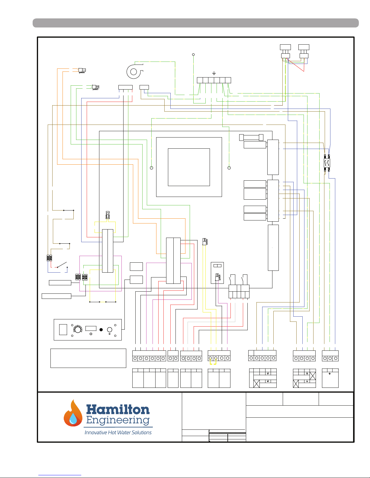
UNIVERSAL WIRING DIAGRAM
03/23/09
34000 Autry St.
Livonia, MI 48150
PH: (800) 968-5530
Fax: (734) 419-0209
Description:
Dwg. By:
Date:
Scale:
Customer:
HAMILTON
ENGINEERING
Dwg.
No.:
Checked.
By:
NTS
K0
K1
K2
K3
K4
=white
=yellow
=brown
=green
=grey
=orange
=blue
=red
=black
=purple
K5
K6
K7
K8
K9
K10
=yellow/green
+-
SETPOINT
TEMPERATURE
BURNER ON
RESET
SERVICE
X 3
21 3 4 5 6
28
2623 2522
L1
L1
Sensor
Indirect
Sensor
Outdoor
Divertor Valve Indirect
L1
Power Supply
Gas Valve-1
X 1
X 2
X 4
X5
X 8
X 9
X 10
Fuse 3.15A
Transformer
1 2 3
4 5 6
fan
2
3
4
5
6
1
1
3
2
6
5
4
1
3
2
6
5
4
7
8
9
10
2
3
4
5
6
7
8
9
1 10
11
12
13
14
15
16
17
18
Gas Valve-2
9
1
8
7
6
5
4
3
2
18
17
16
15
14
13
12
11
10
19
20
fan-1
fan-2
AMP universal
MALE N LOK 350766-1
S1
S2
Main
ST-4
ST-2 ST-6 ST-7
K6
K3
K5
K6
K2
K6
K2
Sensor
or
Aquastat
Pump 2-indirect
OPEN THERM PCB
BURNER
L1
24
ST-3
8
7
Thermostat
Remote
Additional
Heat
Source
Dry
Contact
Dry
Contact
Signal
Lock Out
External
L2
K2
Pressure
switch
Open switch
indicates as H-1
High limit
thermostat
Open switch
indicatesas H-1
1211109
+ -
Cascade
Connection
ST-1
19
17
161513 14
Pump 3
L2
Bridge
+ 0-10
VDC
20
21
1
2
1
2
Molex2121
L2
Pump 1
208-240 Vac
18 27
X7
1 2 543
X6
operating
fault
Pump-2/close
Pump-1
open
Pump-2/comm.
K6
Pump-3
Pump-3
Pump-1
L1L2
K2K2K6
K10
K2K6K10
switch
Gasvalve
Gasvalve
K2
K6
K2
K2
supply L2
supply L1
K2
K6
K10
K10
K10
K10
K10
K10
K10
1A
2A
2
1
open
close
com.
L1L2
K0
K9
21
Cascade PCB
1
2
Thermostat X1/9-18
or OpenTherm PCB X3
Molex2020
Molex2020
ST-5
K10K2K6
K2
K1
K1
flow sensor
K5
K3
return sensor
K2
K2
K2
K2
K2
K9
K9
power supply
fan
pwm/hall
signal
K4
K8
K7
K7
K4
K8
K7
K7
K1
K9
K9
K8
not in use
K8
K8
K7K7K7
K8K0K7
1
2
Molex2020
12
Molex2020
+
-
K2
K10
K1
K3
K1
Universal Wiring Diagram
HW 79 - 599
LowWater Cut Off
K2
Water Flow switch
Open switch
indicates as H-1
Additional Safety Devices
Rear wall
high limit
thermostat
Burner door
high limit
thermostat
34000 Autry Street, Livonia, MI 48150 | 800.968.5530 | Fax 734.419.0209 | www.hamiltonengineering.com | LIT91127US REV 5/2018
Page 65
Page 66

SPECIAL INSTALLATION REQUIREMENTS
PART 9. SPECIAL INSTALLATION REQUIREMENTS
A. INSTALLATION REQUIREMENTS - MASSACHUSETTS
Requirements for installation – Commonwealth of Massachusetts
For all side wall horizontally vented gas fueled equipment installed in every dwelling, building or structure used
in whole or in part for residential purposes, including those owned or operated by the Commonwealth and where
the side wall exhaust vent termination is less than seven (7) feet above nished grade in the area of the venting,
including but not limited to decks and porches, the following requirements shall be satised:
1. INSTALLATION OF CARBON MONOXIDE DETECTORS. At the time of installation of the side wall
horizontal vented gas fueled equipment, the installing plumber or gastter shall observe that a hard wired
carbon monoxide detector with an alarm and battery back-up is installed on the oor level where the gas
equipment is to be installed. In addition, the installing plumber or gastter shall observe that a battery oper-
ated or hard wired carbon monoxide detector with an alarm is installed on each additional level of the dwelling,
building or structure served by the side wall horizontal vented gas fueled equipment. It shall be the responsibility
of the property owner to secure the services of qualied licensed professionals for the installation of hard wired
carbon monoxide detectors
a. In the event that the side wall horizontally vented gas fueled equipment is installed in a
crawl space or an attic, the hard wired carbon monoxide detector with alarm and battery
back-up may be installed on the next adjacent oor level.
b. In the event that the requirements of this subdivision can not be met at the time of completion
of installation, the owner shall have a period of thirty (30) days to comply with the above requirements;
provided, however, that during said thirty (30) day period, a battery operated carbon
monoxide detector with an alarm shall be installed.
2. APPROVED CARBON MONOXIDE DETECTORS. Each carbon monoxide detector as required in
accordance with the above provisions shall comply with NFPA 720 and be ANSI/UL 2034 listed and IAS certied.
3. SIGNAGE. A metal or plastic identication plate shall be permanently mounted to the exterior of the building at
a minimum height of eight (8) feet above grade directly in line with the exhaust vent terminal for the horizontally
vented gas fueled heating appliance or equipment. The sign shall read, in print size no less than one-half (1/2)
inch in size, “GAS VENT DIRECTLY BELOW. KEEP CLEAR OF ALL OBSTRUCTIONS”.
4. INSPECTION. The state or local gas inspector of the side wall horizontally vented gas fueled equipment shall
not approve the installation unless, upon inspection, the inspector observes carbon monoxide detectors and
signage installed in accordance with the provisions of 248 CMR 5.08(2)(a)1 through 4.
(b) EXEMPTIONS: The following equipment is exempt from 248 CMR 5.08(2)(a)1 through 4:
1. The equipment listed in Chapter 10 entitled “Equipment Not Required To Be Vented” in the
most current edition of NFPA 54 as adopted by the Board; and
2. Product Approved side wall horizontally vented gas fueled equipment installed in a room or
structure separate from the dwelling, building or structure used in whole or in part for residential
purposes.
34000 Autry Street, Livonia, MI 48150 | 800.968.5530 | Fax 734.419.0209 | www.hamiltonengineering.com | LIT91127US REV 5/2018
Page 66
Page 67

SPECIAL INSTALLATION REQUIREMENTS
B. INSTALLATION AT HIGH ALTITUDES
This appliance is equipped with an automatic combustion characteristic adjustment system, provided the
installed elevation above sea level is entered into the operating control (FMT 914) when the height is greater
than 2,000 feet and less than or equal to 9,000 feet. To enter the operating elevation:
• Press the reset button continuously for 3 seconds, the appliance shows the adjusted altitude
of the appliance (0 = sea level). Each time the service button is pressed, the value increases by
100 feet (20 through 90 = 2,000 through 9,000 feet). After reaching the maximum value, the
counter returns to the minimum value (example: when the value is 90 and the service button is
pressed, the new value will be 20). When the right altitude has been set (example: 53 = 5,300
feet of elevation above sea level), press the reset button for one second and the value will be
programmed. The factory default is 20 (which equals 2,000 feet), and there is no need to adjust
below that. See Figure 8-3 on page 56 for the button locations.
• The adjusted altitude entered is internally converted to an offset on top of the maximum fan
speed.
• By adjusting the combustion characteristics as described above, there is no de-rate
required at altitudes up to 9,000 feet. For elevations in excess of 9,000 feet or gas BTU
content levels below 950 BTU/cubic foot, consult the factory at 734.419.0200 or 800.968.5530
for adjustments and de-rating information.
PART 10. WARRANTY INFORMATION
A. WARRANTY CONTACT INFORMATION
Hamilton Engineering, Inc. warrants each EVO™ Water Heater and Boiler to be free from defects in material
and workmanship according to terms, conditions and time periods. Unless otherwise noted, these warranties
commence on the date of installation. If required periodic maintenance is not performed, warranty coverage
may be voided.
Warranty information specic to each model can be found on our website www.hamiltonengineering.com,
requested via email at [email protected], or in our printed Product Catalogs.
If you have any questions or comments, please contact us at 800.968.5530. If you need emergency technical
support after hours, we are available 24 hours a day, 7 days a week by calling this number.
Please keep the following information on hand when calling about warranty information:
Model: ___________________________ Serial #: _______________________________________________
Installer Name: ____________________ Phone #: ___________________ Install Date: _______________
34000 Autry Street, Livonia, MI 48150 | 800.968.5530 | Fax 734.419.0209 | www.hamiltonengineering.com | LIT91127US REV 5/2018
Page 67
 Loading...