

Page 1
1
Bedienungsanleitung
Operating Manual
EVN SmartHome
Cube
LAN Gateway (S. 2)
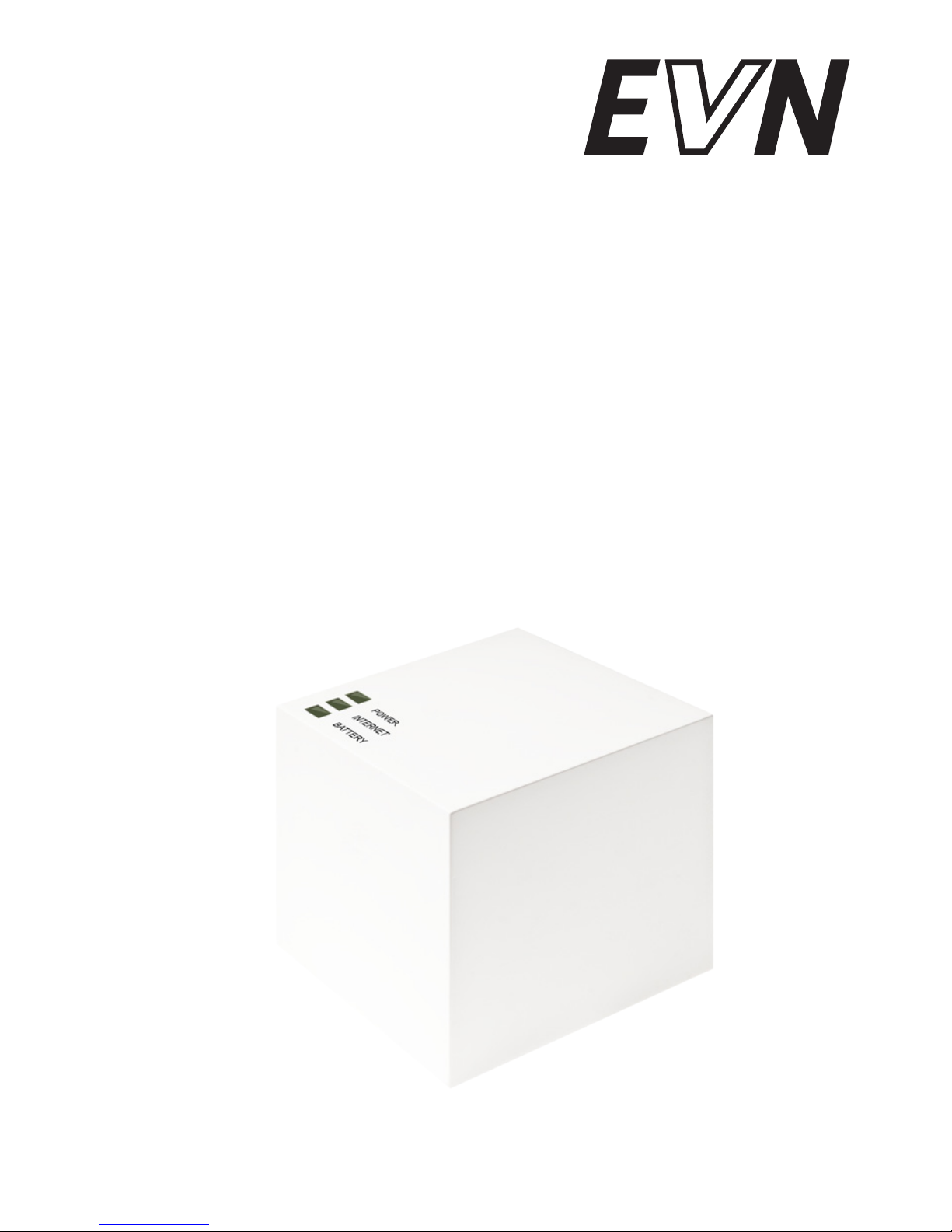
EVN SmartHome Cube
LAN Gateway (p. 12)
eQ-3 AG I BC-LGW-O-TW-EV
Page 2

2
Inhaltsverzeichnis
1. Bestimmungsgemäßer Einsatz ...................................3
2. Übersicht .....................................................................4
3. Sicherheitshinweise ....................................................5
4. Entsorgungshinweise .................................................. 5
5. Montage ......................................................................5
6. Anlernen an das System ............................................. 6
7. Stromversorgung.........................................................6
8. Installation der Gerätesoftware &
Systemvoraussetzungen ............................................7
9. Internetverbindung ......................................................8
10. Werkseinstellungen wieder herstellen ........................8
11. LED-Blinkfolgen und Sendeverhalten ........................9
12. Hinweise zum Funkbetrieb ........................................10
13. Wartung und Reinigung ............................................10
14. Technische Eigenschaften ........................................ 11
Lesen Sie diese Anleitung sorgfältig, bevor Sie das Gerät in Betrieb
nehmen. Bewahren Sie die Anleitung zum späteren Nachlesen auf.
1. Ausgabe Deutsch 10/2011
Dokumentation © 2011 eQ-3 Ltd., Hong Kong.
Alle Rechte vorbehalten.
V1.0
Page 3

3
1. Bestimmungsgemäßer Einsatz
Der Cube ermöglicht die komfortable Konguration der
Komponenten mit der Software und dem Portal. Des
Weiteren lässt sich der Status der einzelnen Komponenten
über den Cube abrufen. Das Gerät ist somit als LAN
Gateway die Datenschnittstelle des Systems und fungiert
zudem als Speicher aller Konfigurationsdaten. Die
Funkkommunikation der Komponenten untereinander
erfolgt bidirektional. Somit ist dafür gesorgt, dass gesendete
Informationen den Empfänger erreichen. Das System
lässt sich bei einer bestehenden Internetverbindung auf
verschiedene Weisen steuern. Auf den Cube kann durch
einen Browser über das Internetportal, über SmartphoneApplikationen sowie über die lokale Software zugegriffen
werden.
Konfigurationen für alle Endgeräte werden bequem
in der Software vorgenommen und lassen sich für
einzelne Räume individuell gestalten. Einstellungen (z.B.
Wochenprole) werden an die Heizkörperthermostate im
System übertragen, damit diese auch autark ohne den
Cube funktionieren.
Betreiben Sie das Gerät nur in Innenräumen und ver-
meiden Sie den Einuss von Feuchtigkeit, Staub sowie
Sonnen- oder Wärmebestrahlung. Jeder andere Einsatz
als in dieser Bedienungsanleitung beschriebene ist
nicht bestimmungsgemäß und führt zu Garantie- und
Haftungsausschluss. Dies gilt auch für Umbauten und
Veränderungen. Die Geräte sind ausschließlich für den
privaten Gebrauch gedacht.
Weitere Informationen zum System und den verfügbaren
Komponenten erhalten Sie auf der Webseite Ihres Vertragspartners.
Page 4
4
2. Übersicht
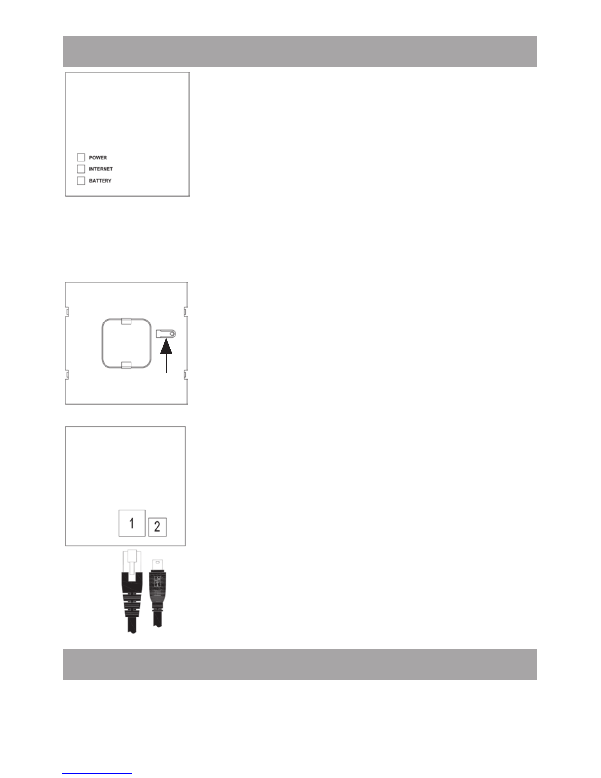
Oberseite:
Power: Die LED zeigt an, ob eine Strom-
versorgung besteht und das Gerät betriebsbereit ist.
Internet: Die LED signalisiert, ob eine Verbindung zum LAN/Internet besteht.
Battery: Die LED zeigt an, ob bei einer Komponente die Batterie auszutauschen ist.
Unterseite:
Reset-Taste: Zum Wiederherstellen der
Werkseinstellung.
Seite:
(1) Netzwerkanschluss zur Verbindung mit
einem Router.
(2) Anschluss für USB Versorgungsspannung (siehe Kapitel 6).
3. Sicherheitshinweise
Die Geräte sind keine Spielzeuge, erlauben Sie Kindern
nicht damit zu spielen. Lassen Sie das Verpackungsmaterial nicht achtlos liegen, dies kann für Kinder zu einem ge-
Page 5
5
fährlichen Spielzeug werden. Öffnen Sie das Gerät nicht,
es enthält keine durch den Anwender zu wartenden Teile. Im Fehlerfall schicken Sie das Gerät an den Service.
4. Entsorgungshinweise
Gerät nicht im Hausmüll entsorgen!
Elektronische Geräte sind entsprechend der Richtlinie
über Elektro- und Elektronik-Altgeräte über die
örtlichen Sammelstellen für Elektronik-Altgeräte
zu entsorgen!
Das CE-Zeichen ist ein Freiverkehrszeichen, das
sich ausschließlich an die Behörden wendet und
keine Zusicherung von Eigenschaften beinhaltet.
5. Montage
Der Cube kann an der Wand befestigt oder, auf seinen
Füßen stehend, aufgestellt werden.
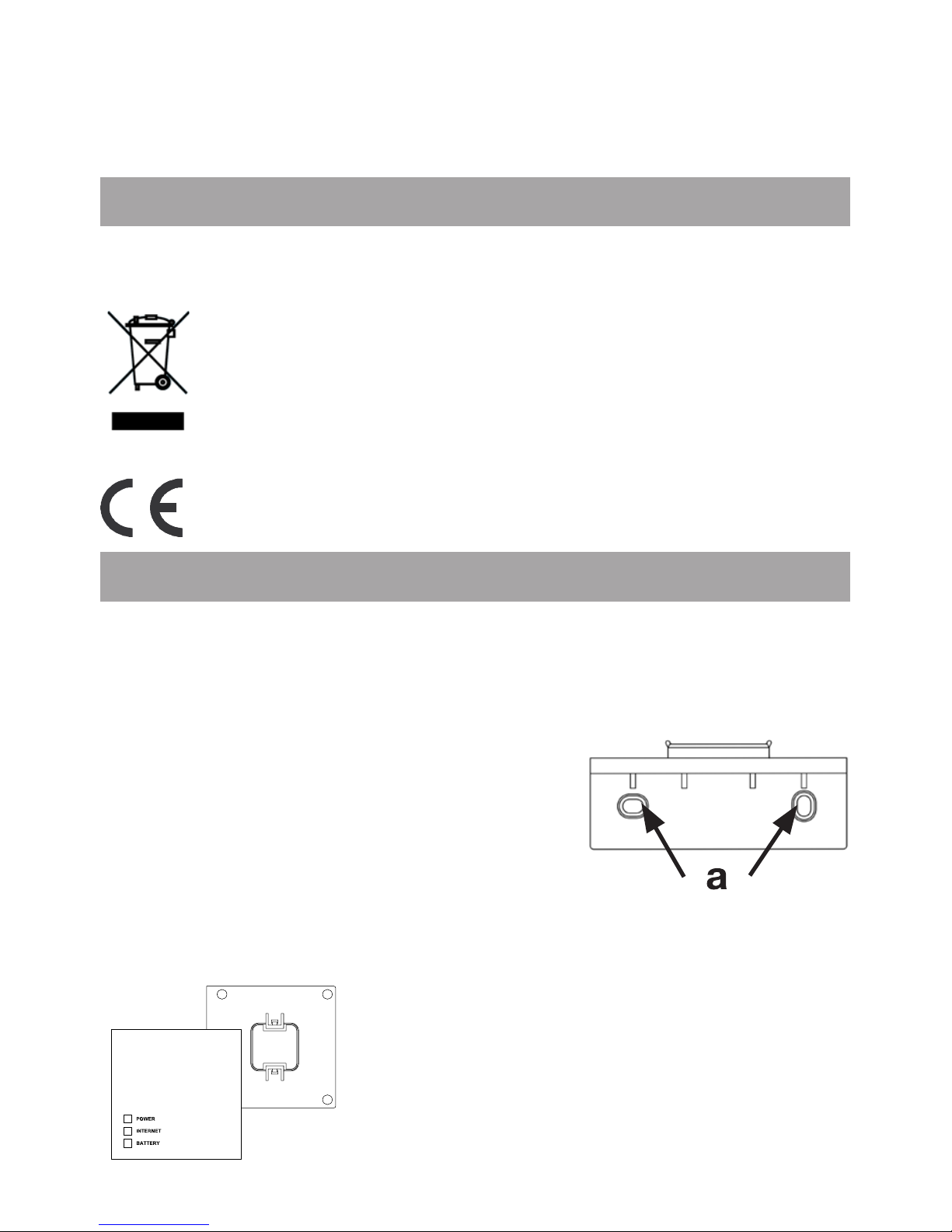
Zur Wandmontage des Cubes verwenden Sie die Wandhalterung:
• Markieren Sie die Bohrlöcher (a)
mit einem Stift an der Wand.
• Bohren Sie die angezeichneten
Löcher (a) mit einem Bohrer.
• Verwenden Sie zur Befestigung der Wandhalterung die
mitgelieferten
Schrauben und Dübel.
• Nach Befestigung der Wandhalterung kann der Cube von oben
mit der Öffnung nach unten auf die
Wandhalterung aufgesetzt werden.
Page 6
6
6. Anlernen an das System
Damit Komponenten miteinander kommunizieren können,
müssen sie aneinander angelernt sein.
Das Anlernen am Cube erfolgt komfortabel über die PC
Software.
7. Stromversorgung
Die Stromversorgung des Cube erfolgt mit dem mitgelieferten Steckernetzteil.
• Stecken Sie das mitgelieferte USB-Netzteil in eine
Steckdose.
• Verbinden Sie den Cube und das Netzteil mit dem USBKabel. Verwenden Sie hierzu die seitlich ange-brachte
USB-Anschlussbuchse (2).
Die Stromversorgung des Cube ist alternativ
auch über den USB Anschluss eines Computers
oder eines Routers möglich. Beachten Sie dabei,
dass bei einigen Modellen die USB Spannung
nach Ausschalten des Gerätes nicht mehr zur Verfügung steht.
Sollte die Stromversorgung zum Cube unterbrochen
sein, regeln die Thermostate die Temperatur in
den Räumen autark weiter. Der Cube dient nur als
Schnittstelle zur Software, zu einem Eco Taster und
als zentraler Datenspeicher.
Achtung: Um Schäden am Gerät zu vermeiden,
benutzen Sie bitte ausschließlich das mitgelieferte
Originalnetzteil für die Stromversorgung.
Page 7
7
8. Installation der PC Software &
Systemvoraussetzungen
Der Cube muss für die Installation der Software
mit Strom versorgt und mit einem Router verbunden sein.
Bei der Inbetriebnahme des Cubes muss DHCP
beim Router aktiviert sein.
Das PC Programm benötigen Sie, um über den Cube Komponenten anzulernen, zu kongurieren und um Statusmeldungen der Geräte abzurufen.
• Verbinden Sie den Cube mit einem Router. Stecken Sie
dazu das mitgelieferte Netzwerkkabel in die dafür vorgesehene Buchse seitlich am Cube. Das andere Ende
stecken Sie in einen freien Steckplatz Ihres Routers.
• Öffnen Sie den Internet-Browser Ihres PCs, auf dem das
PC Programm installiert werden soll.
• Zum Download Ihres PC Programms rufen Sie die EVN
SmartHome Anmeldemaske unter http://loginsmarthome.
evn.at auf und folgen Sie den Hinweisen.
• Starten Sie das heruntergeladene Programm und folgen
Sie den Installationshinweisen.
Systemvoraussetzungen:
• Betriebssystem: Windows XP®, Windows Vista™,
Windows 7
• Browser: Internet Explorer® ab Version 7.0,
Mozilla Firefox® ab Version 3.6.16,
Safari ab Version 5, Google Chrome
ab Version 8
Page 8
8
9. Internetverbindung
Die Konfiguration des Systems erfordert eine lokale
Verbindung zum Heimnetzwerk (LAN) und eine
bestehende Spannungsversorgung des Cube. Um mit
Ihrem Smartphone oder Notebook über das Portal aus
eine Verbindung herzustellen, muss zusätzlich der
Internetzugriff freigeschaltet sein.
Zur dauerhaften Stromversorgung des Cubes sollten Sie das mitgelieferte USB-Netzteil verwenden.
10. Werkseinstellungen wieder herstellen
Der Auslieferungszustand des Cube kann manuell
wieder hergestellt werden. Dabei gehen alle
vorgenommenen Einstellungen und Informationen
über angelernte Geräte unwiderruich verloren.
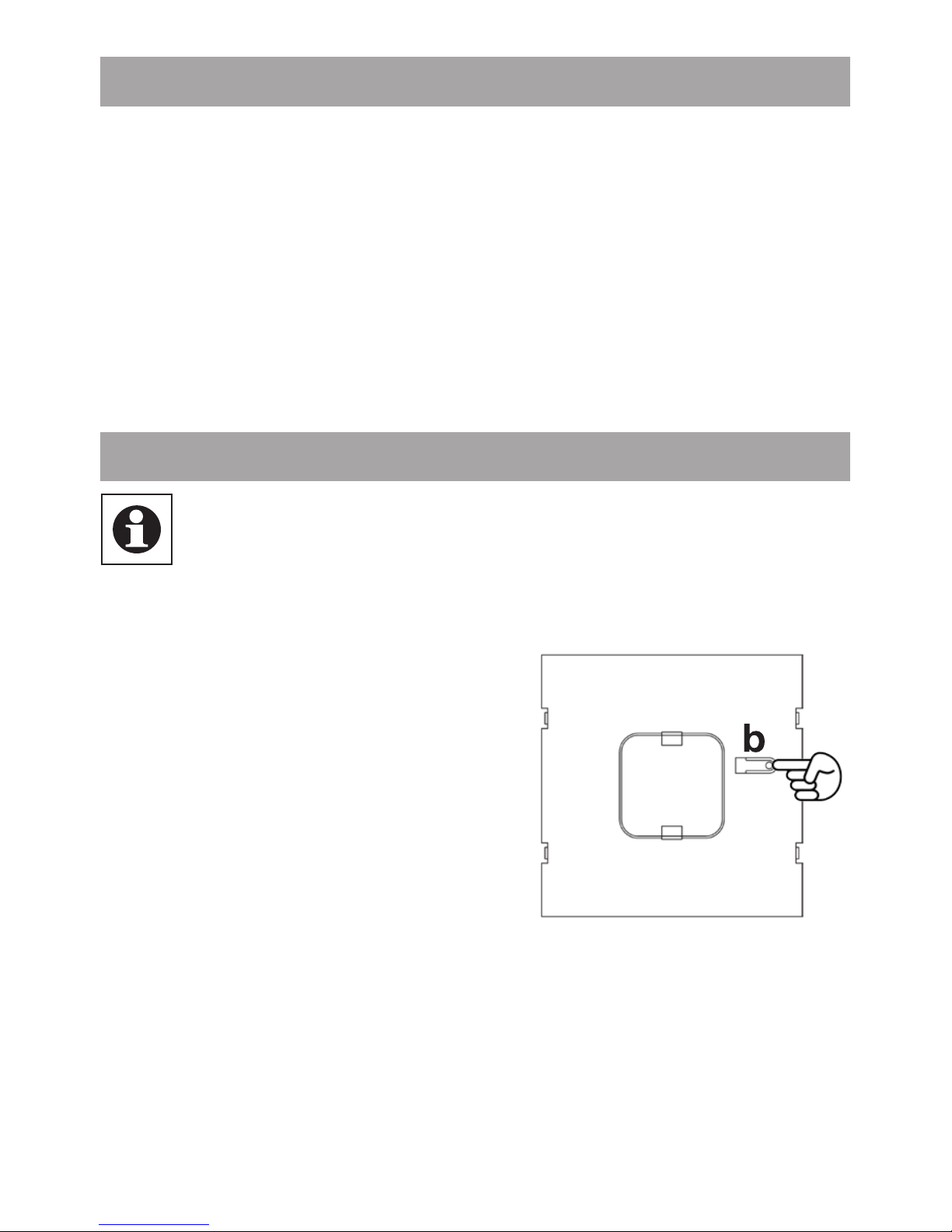
• Trennen Sie den Cube von der
Stromversorgung und warten
Sie 1 Minute.
• Halten Sie nun die Reset-
Taste (b) gedrückt.
• Stellen Sie gleichzeitig die
Stromversorgung wieder her.
• Halten Sie die Reset-Taste
weiterhin gedrückt.
• Die LED leuchtet und beginnt anschließend zu blinken.
Die LED leuchtet wieder permanent.
• Die Werkseinstellungen sind nun wieder hergestellt.
Page 9
9
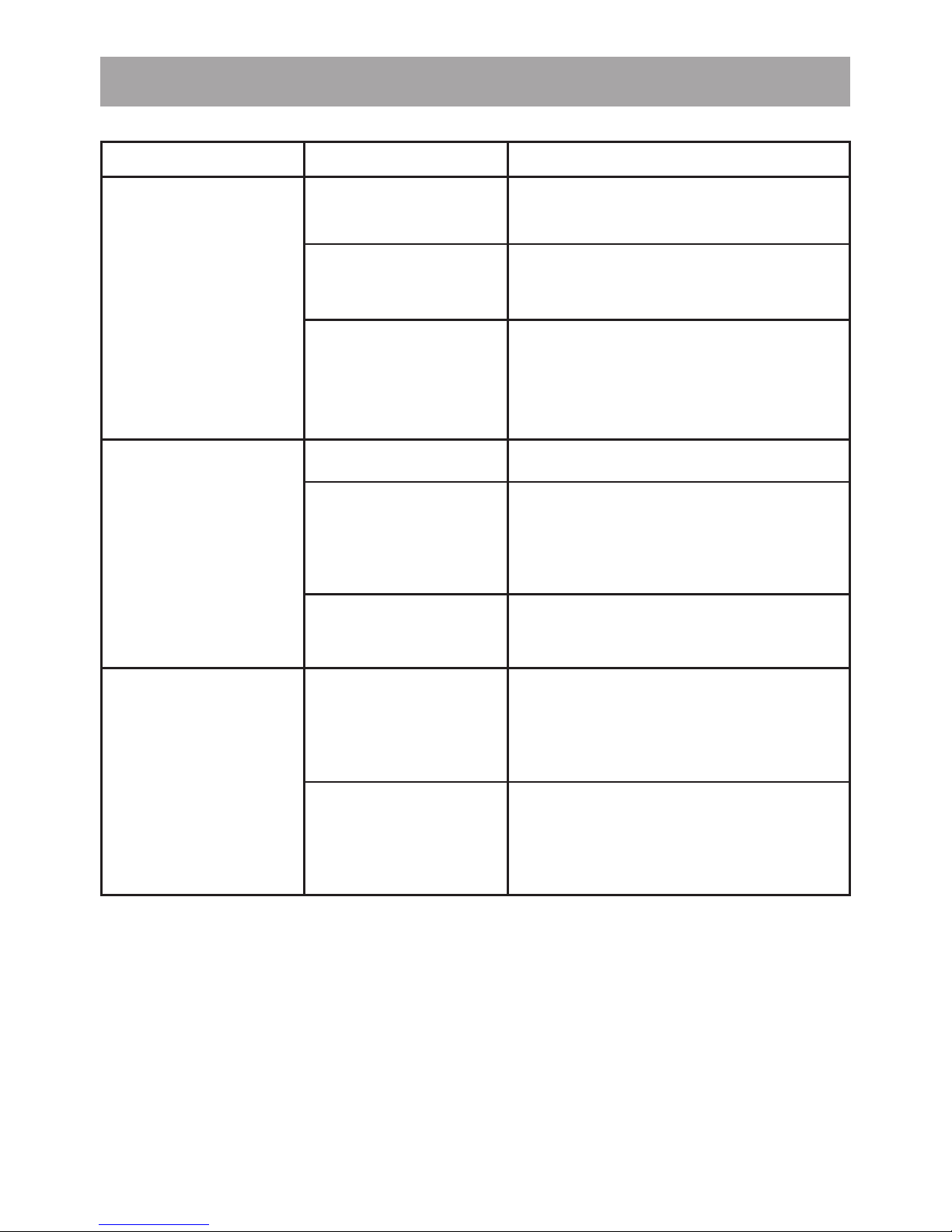
11. LED-Blinkfolgen und Sendeverhalten
LED Zustand Bedeutung
Power-LED LED aus Stromversorgung
unterbrochen
LED blinkt Cube startet und führt
Selbsttest durch
LED leuchtet
dauerhaft
Selbsttest erfolgreich
abgeschlossen und die
Stromversorgung besteht
Internet-LED LED aus Keine Verbindung aktiv
LED blinkt LAN Verbindung zum Router
besteht, keine Verbindung
zum Internet
LED leuchtet
dauerhaft
Verbindung zum Router und
zum Internet aktiv
Battery-LED LED aus Alle Komponenten
haben ausreichend
Batteriespannung
LED blinkt Batterien einer Komponente
müssen ausgetauscht werden
Page 10

10
12. Hinweise zum Funkbetrieb
Die Funkübertragung wird auf einem nicht exklusiven
Übertragungsweg realisiert, weshalb Störungen nicht
ausgeschlossen werden können. Störeinüsse können
u. a. durch Schaltvorgänge, Elektromotoren oder auch
defekte Elektrogeräte hervorgerufen werden.
Die Reichweite in Gebäuden kann stark von der im Freifeld
abweichen. Außer der Sendeleistung und den Empfangs-
eigenschaften der Empfänger spielen Umwelteinüsse
wie Luftfeuchtigkeit neben baulichen Gegebenheiten eine
wichtige Rolle.
Hiermit erklärt die eQ-3 Entwicklung GmbH, dass sich
dieses Gerät in Übereinstimmung mit den grundlegenden
Anforderungen und den anderen relevanten Vorschriften
der Richtlinie 1999/5/EG befindet. Die vollständige
Konformitätserklärung nden Sie unter www.eQ-3.de.
13. Wartung und Reinigung
Das Produkt ist wartungsfrei. Überlassen Sie eine
Reparatur einer Fachkraft. Reinigen Sie das Produkt mit
einem weichen, sauberen, trockenen und fusselfreien
Tuch. Für die Entfernung von stärkeren Verschmutzungen
kann das Tuch leicht mit lauwarmem Wasser angefeuchtet
werden. Verwenden Sie keine lösungsmittelhaltigen
Reinigungsmittel, das Kunststoffgehäuse und die
Beschriftung können dadurch angegriffen werden.
Trennen Sie das Gerät vor der Reinigung vom
Stromnetz.
Page 11

11
14. Technische Eigenschaften
Spannungsversorgung: Input:100 V - 240 V~ / 350 mA
Output: 5V= / 550mA
Gehäusemaße (BxHxT): 80 x 80 x 80 mm
Funkfrequenz: 868,3 MHz
Empfängerklasse: SRD Class 2
Schutzart: IP20
Typische Freifeldreichweite: 100m
Schnittstelle: RJ-45 (Ethernet)
Farbe: weiß
Technische Änderungen sind vorbehalten.
Page 12

12
Table of contents
1. Intended use ..............................................................13
2. Overview ...................................................................14
3. Safety instructions ....................................................15
4. Instructions for disposal ............................................ 15
5. Mounting ....................................................................15
6. Teaching-in to the system..........................................16
7. Power supply ............................................................. 16
8. Installation of device software &
system requirements .................................................17
9. Internet connection ...................................................18
10. Restoring the factory settings ................................... 18
11.
LED ashing sequences and transmission behaviour .1
9
12. Information about radio operation ............................20
13. Maintenance and cleaning ........................................20
14. Technical characteristics ..........................................21
Read this manual carefully before starting to use the device. Keep
the manual so you can refer to it at a later date should you need to.
1st English edition 10/2011
Documentation © 2011 eQ-3 Ltd., Hong Kong.
All rights reserved. V1.0
Page 13

13
1. Intended use
The Cube provides a user-friendly means of conguring
Components with the Software and the Portal. It can also
be used to query the status of the individual components.
As a LAN gateway, the device is thus the data interface
of the system. Furthermore, it provides a storage location
for all conguration data. Radio communication between
Components is bi-directional. This ensures that the information sent reaches the recipient.
With an existing Internet connection, there are various ways
of controlling the system. The Cube can be accessed using a browser via the Internet portal, using a smartphone
application and with the local software.
Conguration settings for all terminals are made via the
user-friendly Software. Different settings can be made for
individual rooms. Settings (e.g. weekly proles) are transmitted to the Radiator Thermostats in the system (so these
also function independently without the Cube).
The device may only be operated indoors and must be
protected from the effects of damp and dust, as well as
solar or heat radiation. Using this device for any purpose
other than that described in this operating manual does not
fall within the scope of intended use and shall invalidate
any warranty or liability. This also applies to any conversion
or modication work. This device is intended for private
use only.
For more information about the System and the available
components, please go to the website of your contracting partner.
Page 14
14
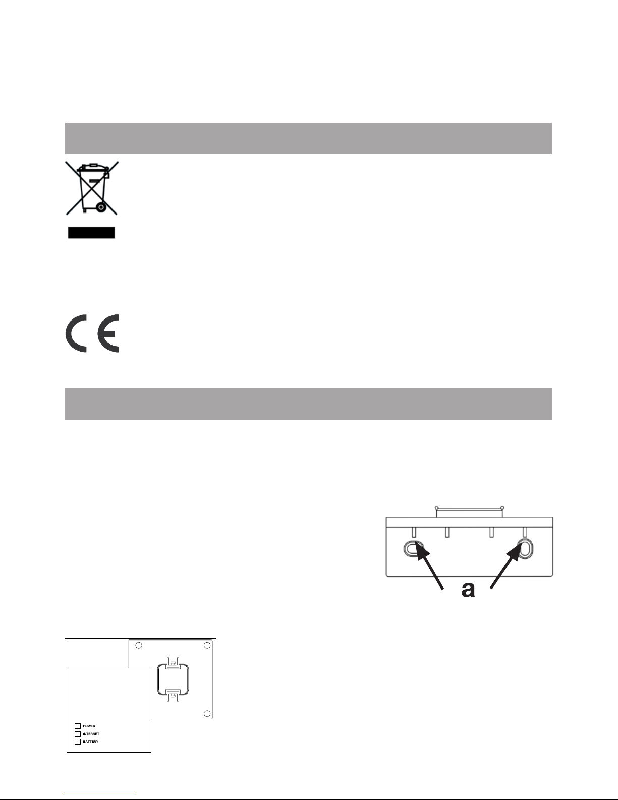
2. Overview
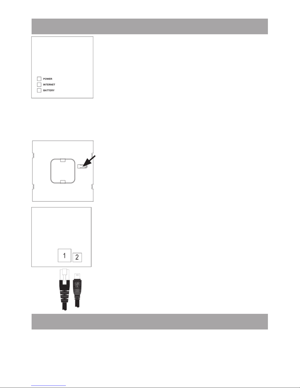
Top:
Power: The LED indicates whether a pow-
er supply is present and if the device is
ready for operation.
Internet: The LED indicates whether a
connection to the LAN/Internet exists.
Battery: The LED indicates whether the
battery needs to be replaced on a Component.
Underside:
Reset button: Restores the factory
setting.
Side:
(1) Network port to connect to a router
(2) Port for for USB power supply (see
Section 6)
3. Safety instructions
This device is not a toy; do not allow children to play with
it. Do not leave packaging material lying around, as it can
be dangerous in the hands of a child. Do not open the
Page 15
15
device: it does not contain any components that need to be
serviced by the user. In the event of an error, please return
the device to our service department.
4. Instructions for disposal
Do not dispose of the device with regular domestic waste!
Electronic equipment must be disposed of at
local collection points for waste electronic equipment in compliance with the Waste Electrical and
Electronic Equipment Directive.
The CE Marking is simply an official symbol
relating to the free movement of a product; it does
not warrant a product’s characteristics.
5. Mounting
The Cube can be installed fastened to the wall or stood
up on its feet.
Use the wall bracket if you wish to mount the Cube on a wall:
• Use a pen to mark the bore hole posi-
t i o n s ( a) o f t h e w a l l m o u n t o n t h e w a l l .
• Use a drill to make the holes as
illustrated (a).
• Use the screws and plugs supplied
to fasten the bracket to the wall.
• Once the wall bracket is in place,
the Cube can be attached to the wall
bracket from above, with the opening
pointing down.
Page 16
16
6. Teaching-in Components
In order to enable communication between Components,
the devices have to be taught-in to one another.
Devices are taught-in on the Cube with the user-friendly
PC software.
7. Power supply
The Cube draws its power supply from the plug-in main
adapter included in the scope of supply.
• Plug the USB main adapter supplied into a socket
outlet.
• Connect the Cube and the main adapter with the USB
cable. Use the USB port on the side of the device (2) for
this purpose.
Alternatively, power can be supplied to the Cube
via the USB port on a computer or a router. Please
note that in the case of some models, the USB voltage is no longer available once the device has been
switched off.
If the power supply to the Cube is interrupted, the
thermostats in the rooms continue to regulate the
temperature independently. The Cube serves solely
as the interface to the Software, to a Eco Switch and
as a central data store.
Attention: To avoid damaging the device, please
only use the original main adapter supplied with the
device for the power supply.
Page 17
17
8. Installation of PC software &
system requirements
The Cube must be supplied with power and connected to router for the installation of the Software.
For the installation of your Cube, the DHCP of your
router has to be activated.
You need the PC program to teach-in Components via
the Cube, for conguration purposes and to call up device
status messages.
• Connect the cube to a router by plugging the network cable supplied with the device into the designated port on
the side of the Cube. Connect the other end of the cable
to a free slot on your router.
• Open the Internet browser on your PC (the one on which
the Software is to be installed).
• To download the PC Program, please open the EVN
SmartHome website http://loginsmarthome.evn.at and
follow the corresponding instructions.
• Start the program you have downloaded and follow the
installation instructions.
System requirements:
• Operating system: Windows XP®, Windows Vista™,
Windows 7
• Browser: Internet Explorer® Version 7.0 or
higher, Mozilla Firefox® Version
3.6.16 or higher, Safari Version 5
or higher, Google Chrome Version
8 or higher
Page 18
18
9. Internet connection
The c onguration of the System requires a local c o nnection
to the home network (LAN) and an existing power supply
to the Cube. To use your smartphone or notebook to
establish a connection via the Portal, Internet access must
also be enabled.
You should use the USB main adapter supplied with the
device for a permanent power supply to the Cube.
10. Restoring the factory settings
The Cube can be reset to the initial state manually.
When the initial state is restored, all information about
taught-in devices and all settings made are lost and
cannot be retrieved.
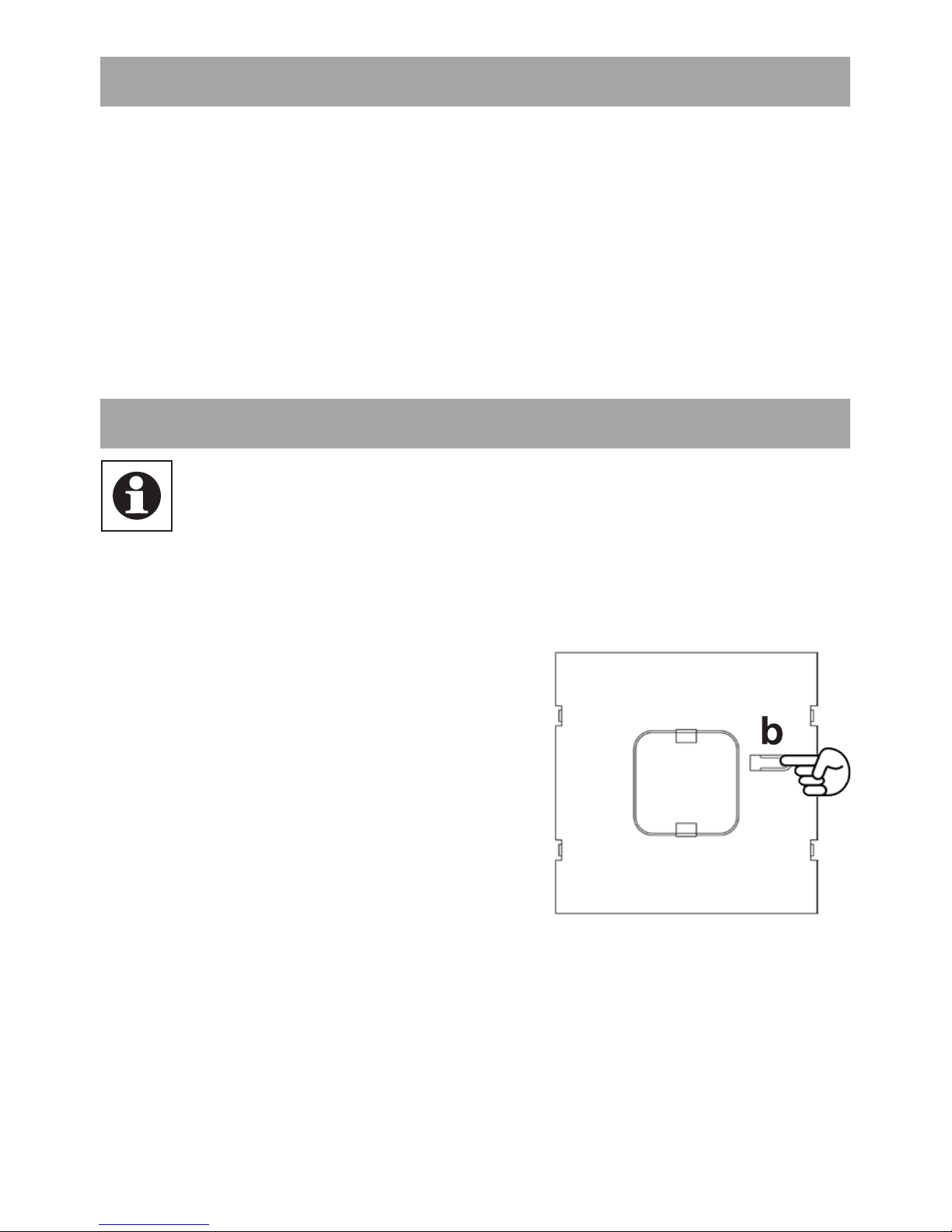
• Start by disconnecting the Cube from the power supply.
• Wait 1 minute.
• Then press and hold down the
Reset button (b).
• At the same time, reconnect the
Cube to the power supply.
• Still hold down the Reset button. The Power LED lights up
and begins to ash.
• The Power LED stays lit now.
• The factory settings are restored.
Page 19
19
11. LED ashing sequences
and transmission behaviour
LED State Meaning
Power LED LED off Power supply interrupted
LED ashing Cube starting up and
performing self-test
LED permanently
lit
Self-test completed
successfully and power
supply present
Internet LED LED off No connection active
LED ashing LAN connection to router
established, no connection
to Internet
LED permanently
lit
Connection to router and to
Internet active
Battery LED LED off All Components have
sufcient battery voltage
LED ashing Batteries of a Component
need to be replaced
Page 20

20
12. Information about radio operation
Radio transmission is performed on a non-exclusive
transmission path, which means that there is a possibility
of interference occurring. Interference can also be caused
by switching operations, electrical motors or defective
electrical devices.
The range of transmission within buildings can differ greatly
from that available in the open air. Besides the transmitting
power and the reception characteristics of the receiver,
environmental factors such as humidity in the vicinity
have an important role to play, as do on-site structural/
screening conditions.
eQ-3 Entwicklung GmbH hereby declares that this device
complies with the essential requirements and other relevant
regulations of Directive 1999/5/EC. You can nd the full
declaration of conformity at www.eQ-3.de.
13. Maintenance and cleaning
The product does not require any maintenance. Enlist the
help of an expert to carry out any repairs. Clean the product
using a soft, lint-free cloth that is clean and dry. You may
dampen the cloth a little with lukewarm water in order to
remove more stubborn marks. Do not use any detergents
containing solvents, as they could corrode the plastic
housing and label.
Disconnect the device from the power supply system
before commencing cleaning.
Page 21

21
14. Technical characteristics
Power supply: Input: 100 V - 240 V~ / 350 mA
Output: 5 V= / 550 mA
Housing dimensions
(W x H x D): 80 x 80 x 80 mm
Radio frequency: 868.3 MHz
Receiver class: SRD Class 2
Degree of protection: IP20
Typical open air range: 100 m
Interface: RJ-45 (Ethernet)
Colour: White
Subject to technical changes.
Page 22

22
Page 23

23
Page 24

24
Hersteller:
eQ-3 AG
Maiburger Straße 29
26789 Leer
www.eQ-3.com
 Loading...