

Evinrude & Johnson ICON 764909, ICON 765381, ICON 764911, ICON 765383, ICON 764912 Instructions Manual
...
Outboard Engines
EVINRUDE® ICON™ BINNACLE MOUNT REMOTE CONTROL KITS
P/N 764909 / 765381, 764910 / 765382, 764911 / 765383, 764912 / 765384, 764913 / 765385
APPLICATION
Use this instruction sheet when installing the above remote control kits on 2008 and newer Evinrude
E-TEC
®
outboards, equipped with the ICON system. DO NOT install on any other models.
SAFETY INFORMATION
The following symbols and/or signal words
may be used in this document:
DANGER
Indicates a hazardous situation which, if
not avoided, will result in death or serious
injury.
WARNING
Indicates a hazardous situation which, if
not avoided, could result in death or serious injury
CAUTION
Indicates a hazardous situation which, if
not avoided, could result in minor or moderate personal injury.
NOTICE
not followed, could severely damage engine
components or other property.
These safety alert signal words mean:
ATTENTION!
BECOME ALERT!
YOUR SAFETY IS INVOLVED!
For safety reasons, this kit must be installed by an
authorized Evinrude
instruction sheet is not a substitute for work
experience. Additional helpful information may be
found in other service literature.
Indicates an instruction which, if
®
/Johnson® dealer. This
DO NOT perform any work until you have read and
understood these instructions completely.
Torque wrench tightening specifications must
strictly be adhered to.
Should removal of any locking fastener (lock tabs,
locknuts, or patch screws) be required, always
replace with a new one.
When replacement parts are required, use
Evinrude/Johnson Genuine Parts or parts with
equivalent characteristics, including type, strength
and material. Use of substandard parts could result
in injury or product malfunction.
Always wear EYE PROTECTION AND
APPROPRIATE GLOVES when using power tools.
Unless otherwise specified, engine must be OFF
when performing this work.
Always be aware of parts that can move, such as
flywheels, propellers, etc.
Some components may be HOT. Always wait for
engine to cool down before performing work.
If you use procedures or service tools that are not
recommended in this instruction sheet, YOU
ALONE must decide if your actions might injure
people or damage the outboard.
This instruction sheet may be translated into other
languages. In the event of any discrepancy, the
English version shall prevail.
TO THE INSTALLER: Give this sheet and the
operating instructions to the owner. Advise the
owner of any special operation or maintenance
information contained in the instructions.
TO THE OWNER: Save these instructions in your
owner’s kit. This sheet contains information
important for the use and maintenance of your
engine.
Printed in the United States.
© 2009 BRP US Inc. All rights reserved.
TM, ® and the BRP logo are registered trademarks of Bombardier Recreational Products Inc. or its affiliates.
DSS09392I REV 1 1 of 20
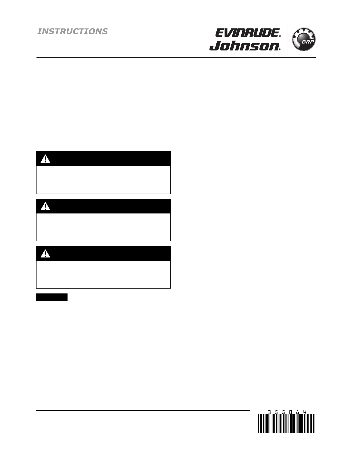
ICON SINGLE LEVER BINNACLE MOUNT REMOTE CONTROL
y
g
g
g
g
p
g
pt (
p
9
10
13
15
14
16, 17
18, 19, 20
12
11
3
4
5
1
2
7, 8
6
007917
Ref P/N Name of Part QtyRef P/N Name of Part Qt
1 764909 CONTROL, Single binnacle - ICON 1 11 ***SCREW, Handle covers 3
2765316 *HARDWARE KIT, Installation 1 12 ***COVER, Inside handle 1
3 **STUD, Control mountin
4 **WASHER, Mountin
5**NUT, Mountin
6 **SEAL, Control mountin
7765355 *CONNECTOR, Switch
8 765356 *TERMINAL 3 183011709 *CONNECTOR, 3 Pin Rc
9765317 *CONTROL HANDLE AY 1 19 3011711 *TERMINAL, Pin 3
10 765319 **HANDLE GRIP KIT 1 20 3011710 *LOCKWEDGE, 3 Pin Rc
2 of 20
anel 1 17 3011713 *LOCKWEDGE, 3 Socket plu
3 13 765318 **SWITCH, Trim/Tilt 1
3 14 3011714 ***TERMINAL, Socket 3
3 15 765354 *SCREW, Handle 1
1163011712 *CONNECTOR, 3 Socket plug (Trim sw)1
1
Trim harness1
t 1
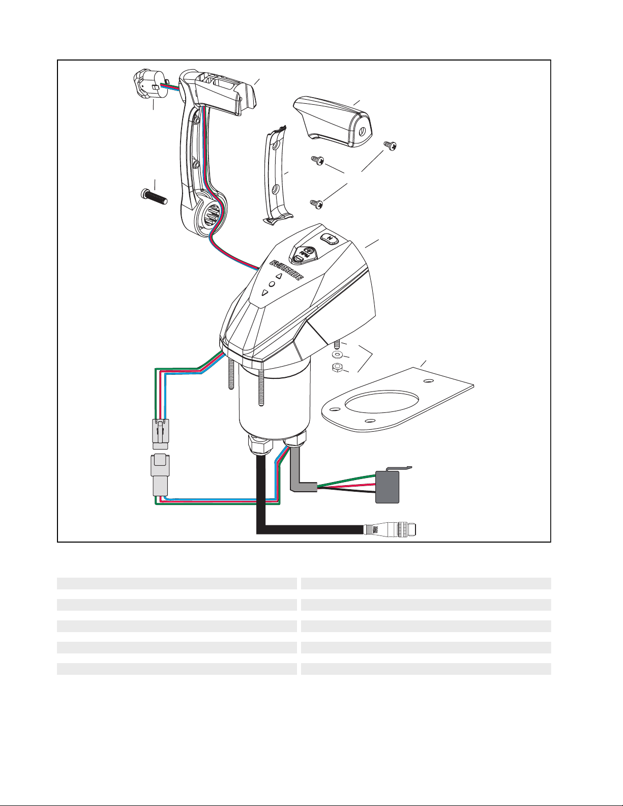
ICON DUAL LEVER BINNACLE MOUNT REMOTE CONTROL
y
g
g
g
g
plug
plug
plug
p
11
15
17
16
10
13
12
13
11
13
1
12
10
14
17
3
2
4
6
5
18, 19
20, 21, 22
7, 8, 9
007918
Ref P/N Name of Part QtyRef P/N Name of Part Qt
1 764910 CONTROL, Single binnacle - ICON 1 12 ***SCREW, Handle covers 3
2765316 *HARDWARE KIT, Installation 1 13 ***COVER, Inside handle 1
3 **STUD, Control mountin
4 **WASHER, Mountin
5**NUT, Mountin
6 **SEAL, Control mountin
7 3011715 *CONNECTOR, 12 Socket
83011714 *TERMINAL, Socket 3 19 3011713 *LOCKWEDGE, 3 Socket
9 3011716 LOCKWEDGE, 12 Socket
10 765317 *CONTROL H AN DLE AY 1 21 3011711 *TERMINAL, Pin 3
11 765319 **HANDLE GRIP KIT 1 22 3011710 *LOCKWEDGE, 3 Pin Rc
4 14 ***COVER, Starboard lever 1
415765318 **SWITCH, Trim/Tilt 1
4163011714 ***TERMINAL, Socket 3
117765354 *SCREW, Handle 1
1183011712 *CONNECTOR, 3 Socket plug (Trim sw)1
20 3011709 *CONNECTOR, 3 Pin Rcpt (Trim harness1
t 1
1
3 of 20
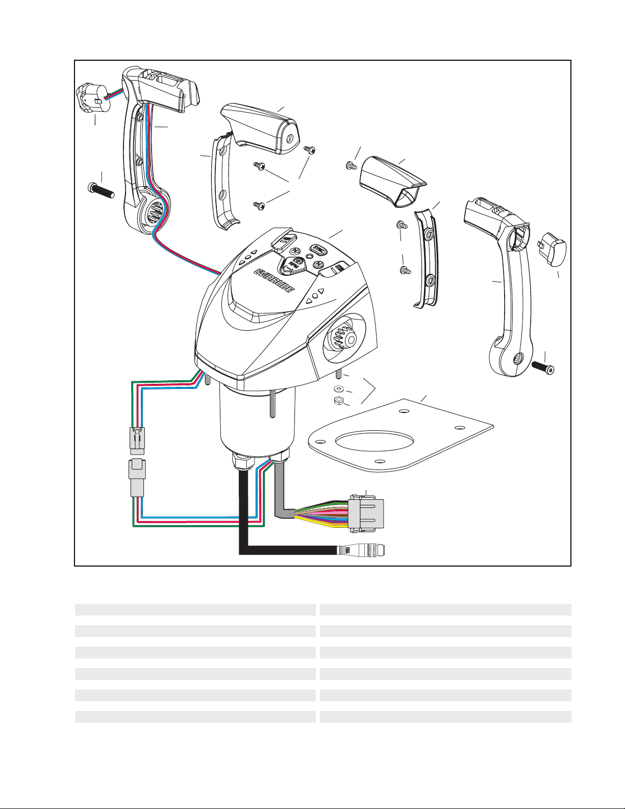
ICON REMOTE CONTROL TRIM PLATES
If upgrading from BRP cable-type binnacle mount remote controls (P/N’s 5006186, 5006184, or
5006182), to an ICON remote control, ICON remote control trim plates are available.
Trim plates cover existing mounting holes and provide pre-drilled mounting for the ICON remote
control.
2 31
Ref P/N Name of Part Qty
1 765075 TRIM PLATE, Single binnacle to ICON (white) 1
1 765076 TRIM PLATE, Single binnacle to ICON (off-white) 1
2 765077 TRIM PLATE, Single binnacle with key switch to ICON (white) 1
2 765078 TRIM PLATE, Single bi nnacle with key switch to IC ON (off-white) 1
3 765079 TRIM PLATE, Dual binnacle to ICON (white) 1
3 765080 TRIM PLATE, Dual binnacle to ICON (off-white) 1
007919
4 of 20
INSTALLATION PROCEDURE
Refer to the ICON System Quick Connection
Guide, P/N 764953 for ICON System Diagram.
Disconnect the battery cables at the battery.
Test remote control operation after installation is
complete.
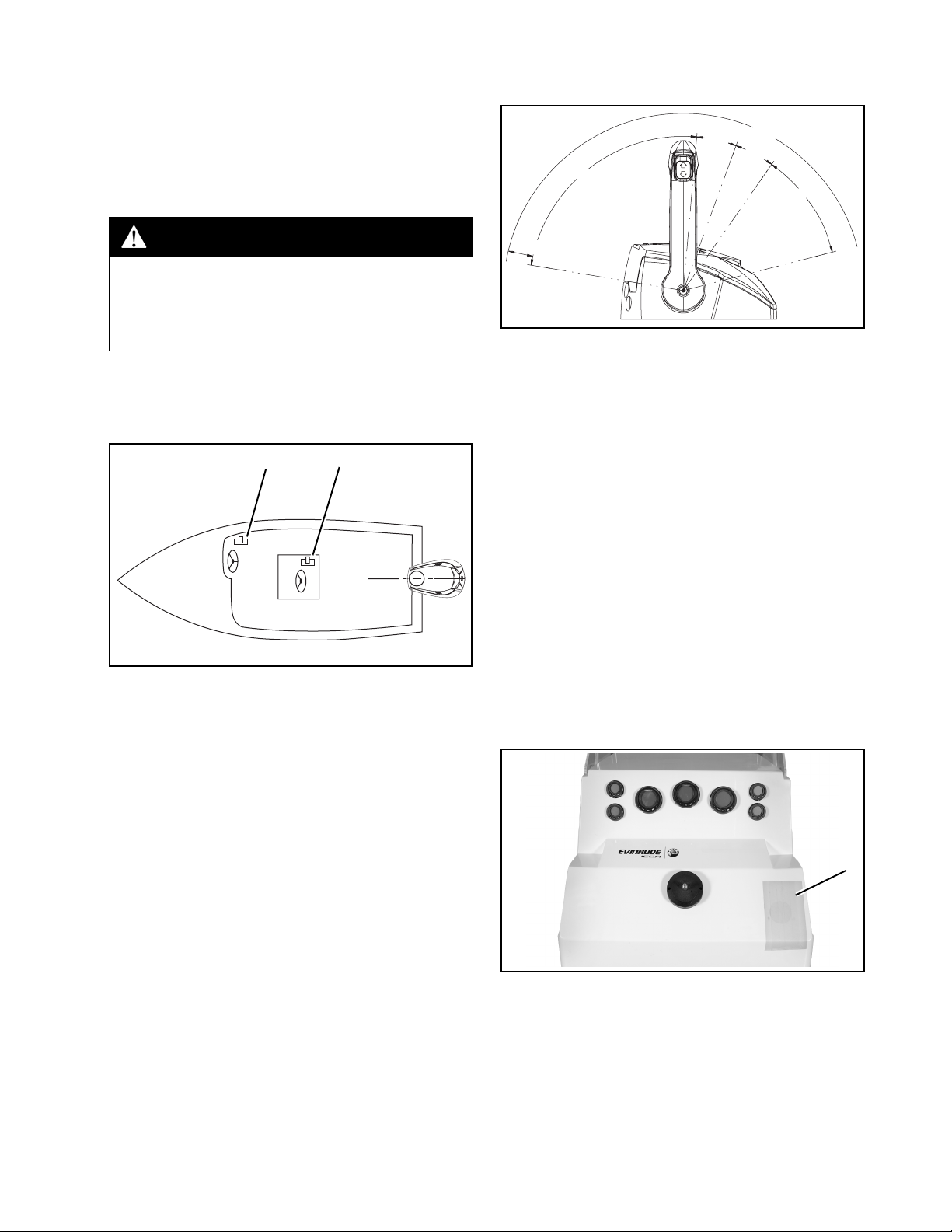
part of the boat throughout the control lever
travel.
FWD
NEUTRAL
15.0°
15.0°
REV
85.5°
40.5°
WARNING
Failure to properly install and test remote
control operation may result in remote
control malfunction and the loss of boat
control.
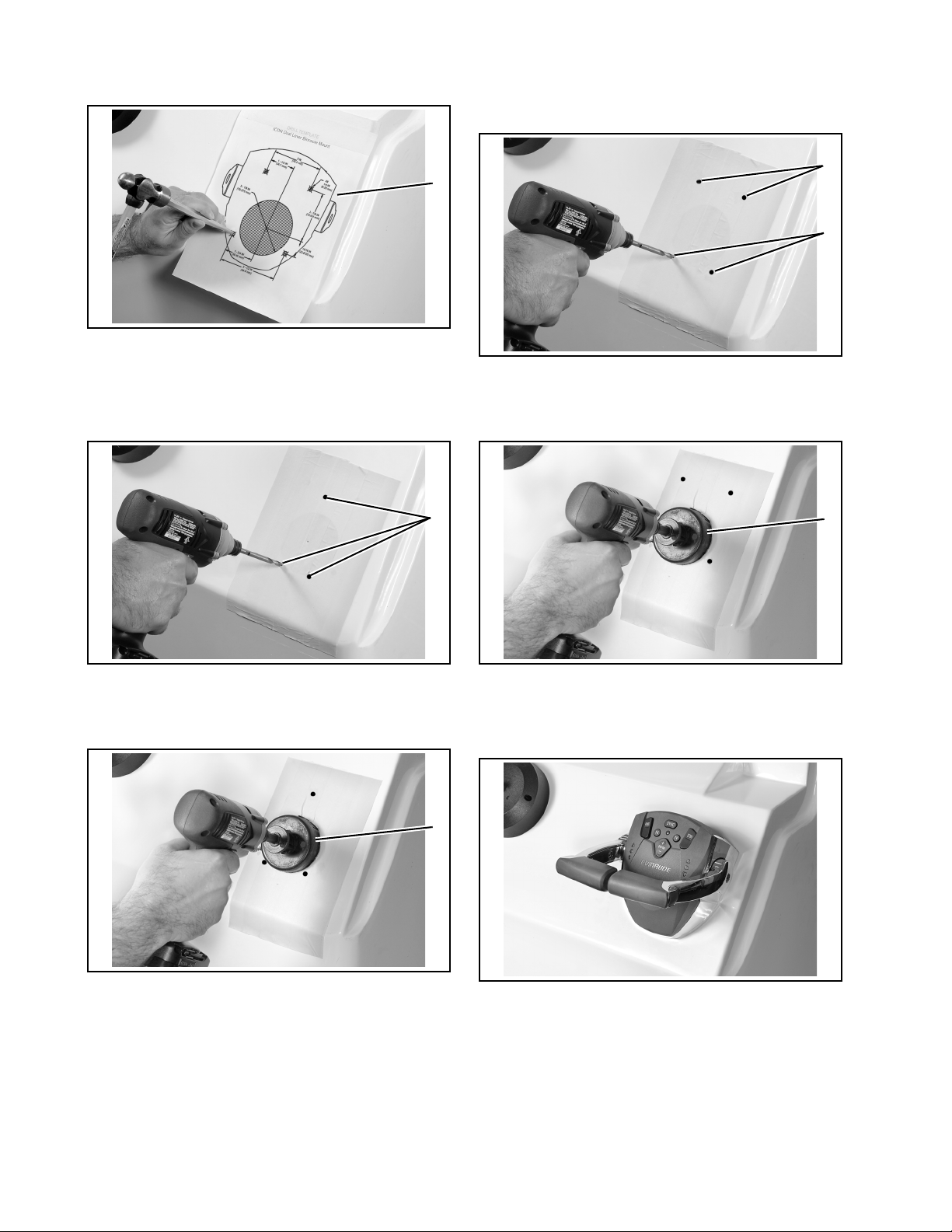
Mounting Location
Select an appropriate location based on the boat
configuration.
1 2
1. Side console
2. Center console
IMPORTANT: The mounting location must be a
flat surface and must be strong enough to provide rigid support. Strengthen mounting surface
as necessary.
005471
2.5 in (64 mm)
007920
There must be at least 5 in. (127 mm) of clear
space below the control for the housing and
network cable routing.
Mounting Holes
Refer to ICON SINGLE BINNACLE REMOTE
CONTROL - DRILL TEMPLATE on page 17 and
ICON DUAL LEVER BINNACLE REMOTE
CONTROL - DRILL TEMPLATE on page 19.
Use appropriate drill template to cut mounting
holes.
IMPORTANT: Make sure the mounting location
has all the required clearances before drilling or
cutting.
Protect mounting surfaces from damage while
drilling. Apply masking tape to fiberglass
surfaces. Use appropriate protection for other
surfaces.
Refer to ICON SINGLE BINNACLE REMOTE
CONTROL PROFILE DRAWING on page 14
and ICON DUAL LEVER BINNACLE REMOTE
CONTROL PROFILE DRAWING on page 15
Place remote control at proposed location and
check clearance around remote control lever at
full throttle in FORWARD and then at full throttle
in REVERSE. There must be at least 2.5 in. (64
mm) of clearance between the handle and any
1
1. Masking tape 007921
5 of 20
Position template. Use center punch to mark the
centers of drill locations.
Dual Lever Binnacle Mount Controls
Drill four (4) 1/4 in. (6.3 mm) holes at the four
mounting stud locations.
1
1. Template 007922
Single Lever Binnacle Mount Controls
Drill three (3) 1/4 in. (6.3 mm) holes at the three
mounting stud locations.
1
1
1
1. Four mounting stud locations 007934
Use a 3-1/8 in (79 mm) hole saw to cut out for the
control base.
1
1. Three mounting stud locations 007923
Use a 3 in (76 mm) hole saw to cut out for the
control base.
1
1. 3-inch hole saw 007933
1. 3 1/8-inch hole saw 007924
Mounting Control
Install control on console.
007925
6 of 20
From under console, install washers and #10
locknuts on studs of control. Tighten locknuts to
a torque of 24 to 36 in. lbs. (2.7 to 4 N·m).
1
Carefully push connectors together and tighten
locking rings finger tight.
1
2
1. Large tabs
2. Small tabs
007883
1. Locknuts 007926
IMPORTANT: Make sure remote control assembly is secured to console and does not move
during operation.
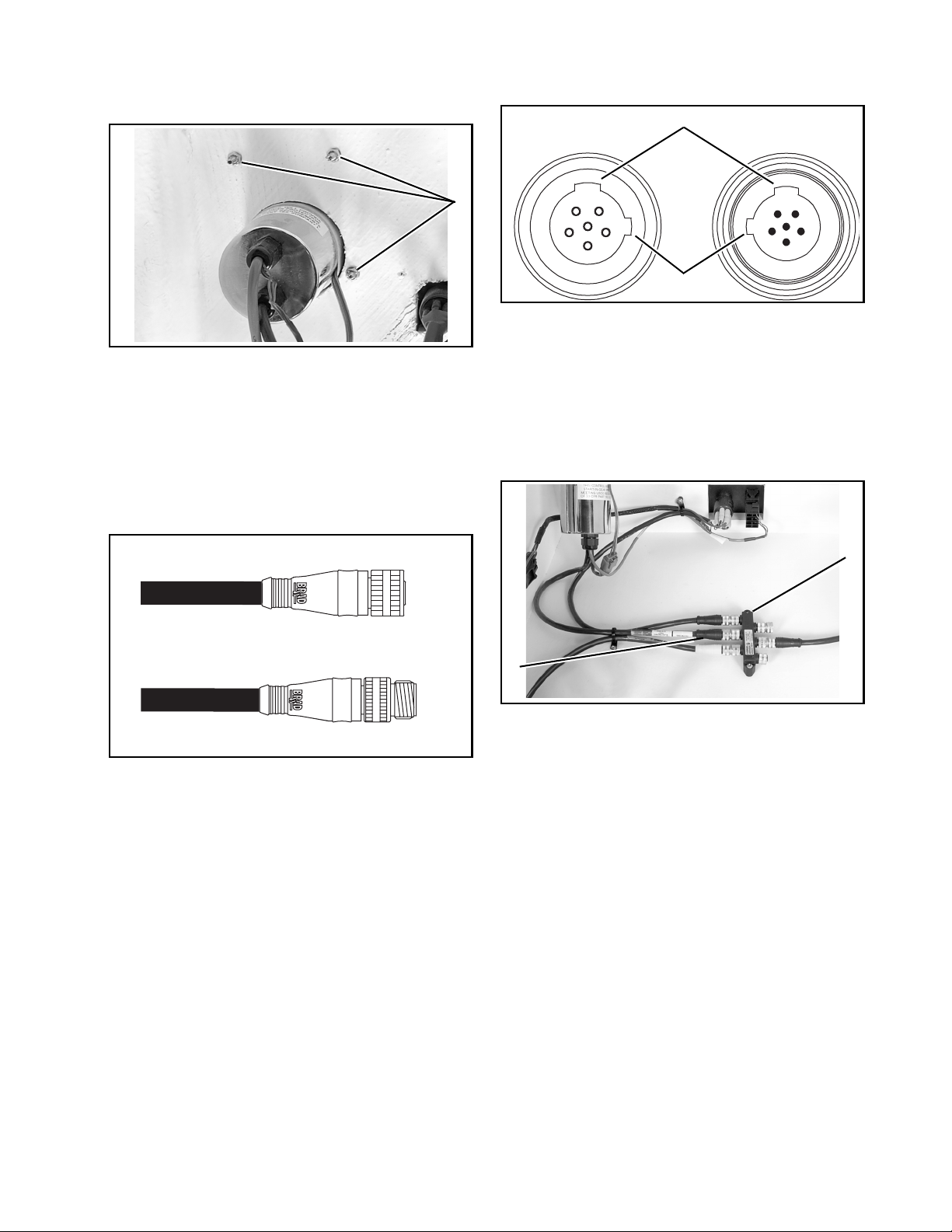
ICON Network Buss Cables
ICON network buss cables use a proprietary
6-pin threaded, Molex-type connector.
1. ICON buss cable connectors 007882
IMPORTANT: Do not force connectors or locking rings. Properly aligned connectors should assemble easily.
ICON Remote Control Connection
Connect remote control buss cable to ICON
network hub.
If the installation requires a buss cable
extension, use no more than one extension.
2
1
1. Remote control buss cable connector
2. ICON network hub
Check operation and movement of control
levers. Make sure remote control shift and
throttle functions operate smoothly. Refer to
REMOTE CONTROL OPERATION TESTS on
page 11.
007884
Do not use Electrical Grease on ICON buss
cable connectors.
Align the tabs of the buss cable connectors.
7 of 20
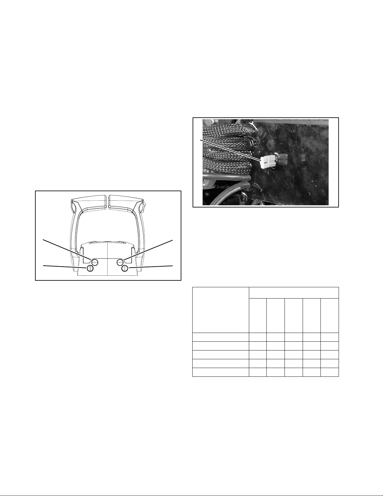
ICON Remote Control Electrical Connections
After all connections are made, connect the battery cables at the battery.
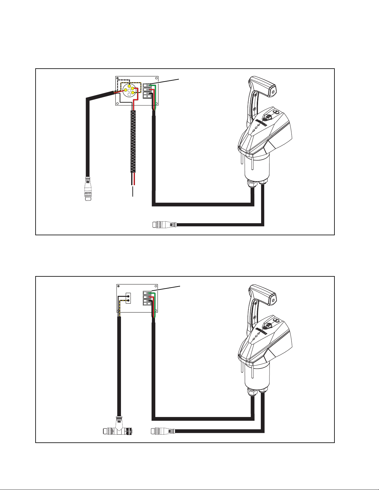
Single Lever Binnacle Mount Control (Single Station)
Install connector from remote control onto START/STOP switch until latched.
1
M
B
A
M
2
3
2
1. Connector
2. To ICON network buss cable/hub
Single Lever Binnacle Mount Control (Second Station)
Install connector from remote control onto START/STOP switch until latched.
3. To gateway module/network power cable
1
007927
2
1. Connector 2. To ICON network buss cable/hub
8 of 20
007929

Dual Lever Binnacle Mount Control (Single Station)
Apply a light coat of Electrical Grease™ onto the seal of the Deutsch connector. Push connectors
together until latched.
M
B
A
M
1
2
3
4
1. Seal
2. Connector
3
3. To ICON network buss cable/hub
4. To gateway module/network power cable
007928
Dual Lever Binnacle Mount Control (Second Station)
Apply a light coat of Electrical Grease™ onto the seal of the Deutsch connector. Push connectors
together until latched.
1
2
1. Seal
2. Connector
3
007930
3. To ICON network buss cable/hub
9 of 20
Control Lever Friction Adjustments
SET ENGINE IDENTITY (Instance)
Check control lever friction. When properly
adjusted, the control lever(s) should have low
friction to allow easy movement in FORWARD
throttle range, and not allow vibration to change
throttle setting.
Use a flat tip screwdriver to adjust friction
adjustment screws. Turn adjustment screws
clockwise to increase the friction or
counterclockwise to reduce the friction.
Shift Friction
This adjustment is used to increase or reduce the
force required to move the control lever to the
FORWARD and REVERSE gear positions only.
Throttle Friction
This adjustment is used to increase or reduce the
force required to move the control lever through
the throttle range.
If this kit is being installed on an outboard in a
multi-engine application, the transom position of
the outboard must be identified on the network.
Engine identity is set by an Engine Identity Plug
installed in the ESM. Outboards are identified as
Instance 0 through 4, from port to starboard, up
to five engines.
Each identity plug is stamped with its instance
number.
1
1. Engine Identity plug 007505
1
2
1. Shift friction adjustment screws
2. Throttle friction adjustment screws
1
2
007931
If the outboard is a single engine or the port
engine in a multi-engine application, no changes
are required.
For all other outboards, engine identity must be
set by replacing the original plug (0) with the plug
that corresponds to the outboard’s position on
the transom.
Identity Numbers
Number of
Outboards
Port
Port
Center
Center
10
20 1
3012
40123
5 01234
Center
Starboard
Starboard
IMPORTANT: The Engine Identity Plug over-
rides any previous EMM instance setting.
10 of 20

REMOTE CONTROL OPERATION TESTS
Emergency Stop Test
NOTICE
DO NOT run outboard without a
water supply to the outboard’s cooling system. Cooling system and/or powerhead damage could occur. Be sure the water intake
screens are below the water surface.
Check Start in Gear Protection
WARNING
Make certain starter will not operate when
the outboard is in gear. The start-in-gear
prevention feature is required by the
United States Coast Guard to help prevent
injuries.
Refer to the ICON User’s Guide or outboard’s
operator’s guide for start procedure and remote
control operation.
Start the outboard and shift into FORWARD
gear.
Turn outboard OFF while remote control is in
FORWARD.
Main Station
Check emergency stop function. Push clip of
emergency stop lanyard onto master power
switch/key switch.
IMPORTANT: If boat is equipped with an optional second or remote station an emergency
stop lanyard must be installed on the emergency
stop switch of the second station. Engine(s) will
not start without emergency stop clip in place.
Refer to Second or Remote Station.
Start the outboard(s). Refer to ICON User’s
Guide.
RUN
OFF
1
Try to restart the outboard. Outboard should not
start.
Shift into NEUTRAL and restart outboard.
Shift into REVERSE gear. Turn outboard OFF
while remote control is in REVERSE.
Try to restart the outboard. Outboard should not
start.
1. Clip of emergency stop lanyard 007895
1
1
2
1. Clip of emergency stop lanyard 007896
With outboard(s) running, remove emergency
stop lanyard. Outboard(s) must STOP. If
outboard does not stop, check master power/key
switch and wiring. Repair as needed.
Reinstall clip on master power/key switch.
11 of 20
Second or Remote Station
Push clip of emergency stop lanyard onto
emergency stop switch. Restart outboard(s).
1
Push clip of emergency stop lanyard onto master
power switch.
1
RUN
OFF
2
1. Clip of emergency stop lanyard 007897
1
1. Clip of emergency stop lanyard 007898
With outboard(s) running remove emergency
stop lanyard from second station emergency
stop switch. Outboard(s) must STOP. If outboard
does not stop, check emergency stop switch and
wiring. Repair as needed.
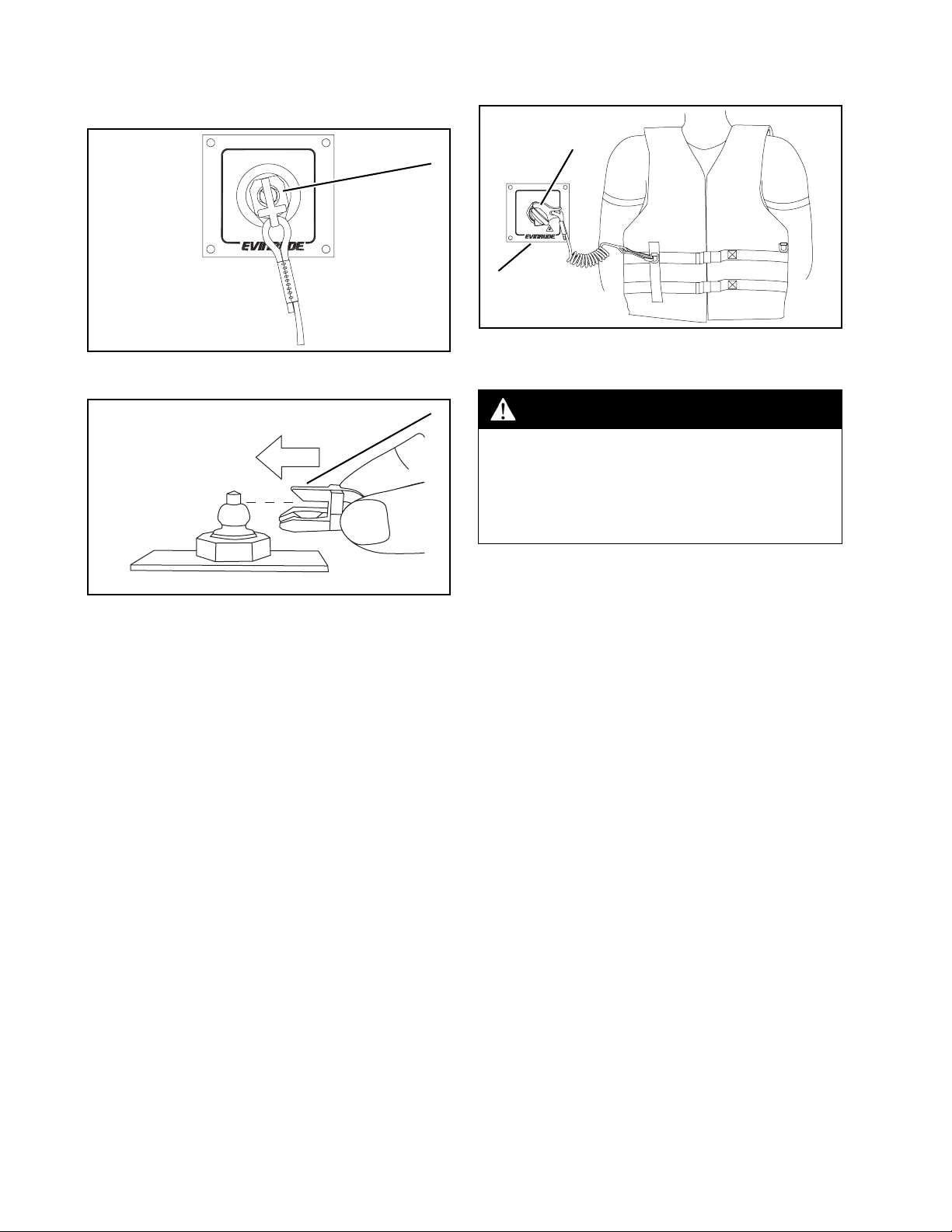
On Water Test
Secure boat to dock to prevent motion. Snap the
emergency stop lanyard to a secure place on the
operators clothing or life vest – not where it might
tear away instead of activating the stop switch.
1. Clip
2. Master power switch
005499A
WARNING
Lanyard MUST be securely attached to
operator, and clip MUST be installed on
master power switch. DO NOT operate
outboard with clip removed from switch,
except in an emergency.
Refer to the ICON User’s Guide for remote
control operation.
Position control lever(s) in the NEUTRAL
position to start or stop outboard.
Turn master power/key switch to RUN position.
Press START symbol of START/STOP switch.
Release switch as soon as outboard starts.
Check shift operation. Check that outboard shifts
into FORWARD gear when control is shifted to
FORWARD, and shifts to REVERSE gear when
control is shifted to REVERSE.
12 of 20
 Loading...