

Evinrude & Johnson E90DPLSCB, E90DPXSCB, E75DSLSCS, E75DPLSCB, E90WDELSCS Service Manual
...
Service Manual
75, 90 HP


BRP US Inc.
Technical Publications
250 Sea Horse Drive
Waukegan, Illinois 60085 United States
† AMP, Superseal 1.5, Super Seal, Power Timer, and Pro-Crimper II
are registered trademarks of Tyco International, Ltd.
† Amphenol is a registered trademark of The Amphenol Corporation.
† Champion is a registered trademark of Federal-Mogul Corporation.
† Deutsch is a registered trademark of The Deutsch Company.
† Dexron is a registered trademark of The General Motors Co rporation.
† Fluke is a registered trademark of The Fluke Corporation
† GE is a registered trademark of The General Electric Company.
† GM is a registered trademark of The General Motors Corporation.
† Locquic and Loctite are registered trademarks of The Henkel Group.
† Lubriplate is a registered trademark of Fiske Brothers Refining Company.
† NMEA is a registered trademark of the National Marine Electronics Association.
† Oetiker is a registered trademark of Hans Oetiker AG Maschinen.
† Packard is a registered trademark of Delphi Automotive Systems.
† Permatex is a registered trademark of Permatex.
† STP is a registered trademark of STP Products Company.
† Snap-on is a registered trademark of Snap-on Technologies, Inc.
The following trademarks are the property of BRP US Inc. or its affiliates:
Evinrude
Johnson
Evinrude
®
®
®
E-TEC
®
Nut Lock™
Screw Lock™
Ultra Lock™
FasTrak™ Gel-Seal II™
S.A.F.E.™ Moly Lube™
SystemCheck™
Triple-Guard
®
Grease
I-Command™ DPL™ Lubricant
Evinrude
Evinrude
Evinrude
®
/ Johnson ® XD30™ Outboard Oil 2+4 ® Fuel Conditioner
®
/ Johnson ® XD50™ Outboard Oil
®
/ Johnson ® XD100™ Outboard Oil
Carbon Guard™
HPF XR™ Gearcase Lubricant
Twist Grip™
Printed in the United States.
© 2007 BRP US Inc. All rights reserved.
TM, ® Trademarks and registered trademarks of Bombardier Recreational Products Inc. or its affiliates.

TABLE
OF
CONTENTS
SECTION . . . . . . . . . . . . . . . . . . . . . . . . . . . . . . . . . . . . . PAGE
INTRODUCTION . . . . . . . . . . . . . . . . . . . . . . . . . . . . . . . . . . . 3
1 SPECIAL TOOLS . . . . . . . . . . . . . . . . . . . . . . . . . . . . . . 13
2 INSTALLATION AND PREDELIVERY . . . . . . . . . . . . . . 25
3 MAINTENANCE . . . . . . . . . . . . . . . . . . . . . . . . . . . . . . . 65
4 ENGINE COVER SERVICE . . . . . . . . . . . . . . . . . . . . . . 81
5 ENGINE MANAGEMENT MODULE (EMM) . . . . . . . . . . 85
6 SYSTEM ANALYSIS . . . . . . . . . . . . . . . . . . . . . . . . . . . 103
7 ELECTRICAL AND IGNITION . . . . . . . . . . . . . . . . . . . . 117
8 FUEL SYSTEM . . . . . . . . . . . . . . . . . . . . . . . . . . . . . . . 153
9 OILING SYSTEM . . . . . . . . . . . . . . . . . . . . . . . . . . . . . 175
10 COOLING SYSTEM . . . . . . . . . . . . . . . . . . . . . . . . . . . 189
11 POWERHEAD . . . . . . . . . . . . . . . . . . . . . . . . . . . . . . . . 199
12 MIDSECTION . . . . . . . . . . . . . . . . . . . . . . . . . . . . . . . . 235
13 GEARCASE . . . . . . . . . . . . . . . . . . . . . . . . . . . . . . . . . 257
14 TRIM AND TILT . . . . . . . . . . . . . . . . . . . . . . . . . . . . . . . 287
SAFETY . . . . . . . . . . . . . . . . . . . . . . . . . . . . . . . . . . . . . . .S–1
INDEX . . . . . . . . . . . . . . . . . . . . . . . . . . . . . . . . . . . . . . . . . .I–1
TROUBLE CHECK CHART . . . . . . . . . . . . . . . . . . . . . . . . T–1
DIAGRAMS
EMM SERVICE CODE CHART
2

INTRODUCTION
INTRODUCTION
CONTENTS
ABBREVIATIONS USED IN THIS MANUAL . . . . . . . . . . . . . . . . . . . . . . . . . . . . . . . . . . . . . . . . . . . . . . . .6
UNITS OF MEASUREMENT . . . . . . . . . . . . . . . . . . . . . . . . . . . . . . . . . . . . . . . . . . . . . . . . . . . . . . . . . . . .6
LIST OF ABBREVIATIONS . . . . . . . . . . . . . . . . . . . . . . . . . . . . . . . . . . . . . . . . . . . . . . . . . . . . . . . . . . . . . 6
ENGINE EMISSIONS INFORMATION . . . . . . . . . . . . . . . . . . . . . . . . . . . . . . . . . . . . . . . . . . . . . . . . . . . . .7
MANUFACTURER’S RESPONSIBILITY . . . . . . . . . . . . . . . . . . . . . . . . . . . . . . . . . . . . . . . . . . . . . . . . . . . .7
DEALER’S RESPONSIBILITY . . . . . . . . . . . . . . . . . . . . . . . . . . . . . . . . . . . . . . . . . . . . . . . . . . . . . . . . . . .7
OWNER’S RESPONSIBILITY . . . . . . . . . . . . . . . . . . . . . . . . . . . . . . . . . . . . . . . . . . . . . . . . . . . . . . . . . . .7
EPA EMISSION REGULATIONS . . . . . . . . . . . . . . . . . . . . . . . . . . . . . . . . . . . . . . . . . . . . . . . . . . . . . . . . .7
MODEL DESIGNATION . . . . . . . . . . . . . . . . . . . . . . . . . . . . . . . . . . . . . . . . . . . . . . . . . . . . . . . . . . . . . . . .8
MODELS COVERED IN THIS MANUAL . . . . . . . . . . . . . . . . . . . . . . . . . . . . . . . . . . . . . . . . . . . . . . . . . . .9
IDENTIFYING MODEL AND SERIAL NUMBERS . . . . . . . . . . . . . . . . . . . . . . . . . . . . . . . . . . . . . . . . . . . . . .9
SERVICE SPECIFICATIONS . . . . . . . . . . . . . . . . . . . . . . . . . . . . . . . . . . . . . . . . . . . . . . . . . . . . . . . . . . .10
STANDARD TORQUE SPECIFICATIONS . . . . . . . . . . . . . . . . . . . . . . . . . . . . . . . . . . . . . . . . . . . . . . . .12
PRODUCT REFERENCE AND ILLUSTRATIONS . . . . . . . . . . . . . . . . . . . . . . . . . . . . . . . . . . . . . . . . . . .12
3
SAFETY INFORMATION
Before working on any part of the outboard, read the SAFETY section at the end of this manual.
This manual is written for qualified, factory-trained
technicians who are already familiar with the use
of Evinrude
ual is not a substitute for work experience. It is an
organized guide for reference, repair, and maintenance of the outboard(s).
This manual uses the following signal words identifying important safety messages.
®
/Johnson® Special Tools. This man-
DANGER
Indicates an imminently hazardous situation which, if not avoided, WILL result in
death or serious injury.
WARNING
Indicates a potentially hazardous situation
which, if not avoided, CAN result in severe
injury or death.
Always follow common shop safety practices. If
you have not had training related to common shop
safety practices, you should do so to protect yourself, as well as the people around you.
It is understood that this manual may be translated into other languages. In the event of any discrepancy, the English version shall prevail.
To reduce the risk of personal injury, safety warnings are provided at appropriate times throughout
the manual.
DO NOT make any repairs until you have read the
instructions and checked the pictures relating to
the repairs.
Be careful, and never rush or guess a service procedure. Human error is caused by many factors:
carelessness, fatigue, overload, preoccupation,
unfamiliarity with the product, and drugs and alcohol use, to name a few. Damage to a boat and
outboard can be fixed in a short period of time, but
injury or death has a lasting effect.
CAUTION
Indicates a potentially hazardous situation
which, if not avoided, MAY result in minor
or moderate personal injury or property
damage. It also may be used to alert
against unsafe practices.
IMPORTANT: Identifies information that will help
prevent damage to machinery and appears next
to information that controls correct assembly and
operation of the product.
These safety notices mean:
ATTENTION!
BECOME ALERT!
YOUR SAFETY IS INVOLVED!
When replacement parts are required, use
Evinrude/Johnson Genuine Parts or parts with
equivalent characteristics, including type, strength
and material. Using substandard parts could result
in injury or product malfunction.
Torque wrench tightening specifications must be
strictly followed. Replace any locking fastener
(locknut or patch screw) if its locking feature
becomes weak. Definite resistance to turning
must be felt when reusing a locking fastener. If
replacement is specified or required because the
locking fastener has become weak, use only
authorized Evinrude/Johnson Genuine Parts.
If you use procedures or service tools that are not
recommended in this manual, YOU ALONE must
decide if your actions might injure people or damage the outboard.

DANGER
Contact with a rotating propeller is likely to result in serious injury or death. Assure the
engine and prop area is clear of people and objects before starting engine or operating boat.
Do not allow anyone near a propeller, even when the engine is off. Blades can be sharp and
the propeller can continue to turn even after the engine is off. Remove propeller before servicing and when running the outboard on a flushing device.
DO NOT run the engine indoors or without adequate ventilation or permit exhaust fumes to
accumulate in confined areas. Engine exhaust contains carbon monoxide which, if inhaled,
can cause serious brain damage or death.
WARNING
Wear safety glasses to avoid personal injury, and set compressed air to less than 25 psi (172
kPa).
The motor cover and flywheel cover are machinery guards. Use caution when conducting
tests on running outboards. DO NOT wear jewelry or loose clothing. Keep hair, hands, and
clothing away from rotating parts.
During service, the outboard may drop unexpectedly. Avoid personal injury; always support
the outboard’s weight with a suitable hoist or the tilt support bracket during service.
To prevent accidental starting while servicing, disconnect the battery cables at the battery.
Twist and remove all spark plug leads.
The electrical system presents a serious shock hazard. DO NOT handle primary or secondary
ignition components while outboard is running or flywheel is turning.
Gasoline is extremely flammable and highly explosive under certain conditions. Use caution
when working on any part of the fuel system.
Protect against hazardous fuel spray. Before starting any fuel system service, carefully
relieve fuel system pressure.
Do not smoke, or allow open flames or sparks, or use electrical devices such as cellular
phones in the vicinity of a fuel leak or while fueling.
Keep all electrical connections clean, tight, and insulated to prevent shorting or arcing and
causing an explosion.
Always work in a well ventilated area.
Replace any locking fastener (locknut or patch screw) if its locking feature becomes weak.
Definite resistance to tightening must be felt when reusing a locking fastener. If replacement
is indicated, use only authorized replacement or equivalent.

INTRODUCTION
ABBREVIATIONS USED IN THIS MANUAL
ABBREVIATIONS USED IN THIS MANUAL
Units of Measurement List of Abbreviations
A Amperes
amp-hr Ampere hour
fl. oz. fluid ounce
ft. lbs. foot pounds
HP horsepower
in. inch
in. Hg inches of mercury
in. lbs. inch pounds
kPa kilopascals
ml milliliter
mm millimeter
N·m Newton meter
P/N part number
psi pounds per square inch
RPM revolutions per minute
°C degrees Celsius
°F degrees Fahrenheit
ms milliseconds
µs microseconds
Ω Ohms
VVolts
VAC Volts Alternating Current
VDC Volts Direct Current
ABYC American Boat & Yacht Council
ATDC after top dead center
AT air temperature sensor
BPS barometric pressure sensor
BTDC before top dead center
CCA cold cranking amps
CPS crankshaft position sensor
EMM Engine Management Module
ICOMIA International Council of Marine
Industry Associations
MCA marine cranking amps
MWS modular wiring system
NMEA National Marine Electronics Assoc.
NTC negative temperature coefficient
PTC positive temperature coefficient
ROM read only memory
S.A.F.E.™ speed adjusting failsafe electronics
SAC start assist circuit
SAE Society of Automotive Engineers
SYNC synchronization
TDC top dead center
TPS throttle position sensor
WOT wide open throttle
WTS water temperature sensor
6

INTRODUCTION
ENGINE EMISSIONS INFORMATION
ENGINE EMISSIONS
INFORMATION
Maintenance, replacement, or repair of the
emission control devices and systems may be
performed by any marine SI (spark ignition)
engine repair establishment or individual.
Manufacturer’s Responsibility
Beginning with 1999 model year outboards, manufacturers of marine outboards must determine
the exhaust emission levels for each outboard
horsepower family and certify these outboards
with the United States of America Environmental
Protection Agency (EPA). An emissions control
information label, showing emission levels and
outboard specifications, must be placed on each
outboard at the time of manufacture.
Dealer’s Responsibility
When performing service on all 1999 and more
recent Evinrude/Johnson outboards that carry an
emissions control information label, adjustments
must be kept within published factory specifications.
Replacement or repair of any emission related
component must be executed in a manner that
maintains emission levels within the prescribed
certification standards.
Dealers are not to modify the outboard in any
manner that would alter the horsepower or allow
emission levels to exceed their predetermined
factory specifications.
Exceptions include manufacturer’s prescribed
changes, such as altitude adjustments, for example.
Owner’s Responsibility
The owner/operator is required to have outboard
maintenance performed to maintain emission levels within prescribed certification standards.
The owner/operator is not to, and should not allow
anyone to, modify the outboard in any manner
that would alter the horsepower or allow emissions levels to exceed their predetermined factory
specifications.
Tampering with the fuel system to change horsepower or modify emission levels beyond factory
settings or specifications will void the product warranty.
EPA Emission Regulations
All new 1999 and more recent Evinrude/Johnson
outboards are certified to the EPA as conforming
to the requirements of the regulations for the control of air pollution from new watercraft marine
spark ignition outboards. This certification is contingent on certain adjustments being set to factory
standards. For this reason, the factory procedure
for servicing the product must be strictly followed
and, whenever practical, returned to the original
intent of the design. The responsibilities listed
above are general and in no way a complete listing of the rules and regulations pertaining to the
EPA requirements on exhaust emissions for
marine products. For more detailed information on
this subject, you may contact the following locations:
VIA U.S. POSTAL SERVICE:
Office of Mobile Sources
Engine Programs and Compliance Division
Engine Compliance Programs Group (6403J)
401 M St. NW
Washington, DC 20460
VIA EXPRESS or COURIER MAIL:
Office of Mobile Sources
Engine Programs and Compliance Division
Engine Compliance Programs Group (6403J)
501 3rd St. NW
Washington, DC 20001
EPA INTERNET WEB SITE:
www.epa.gov
7
INTRODUCTION
MODEL DESIGNATION
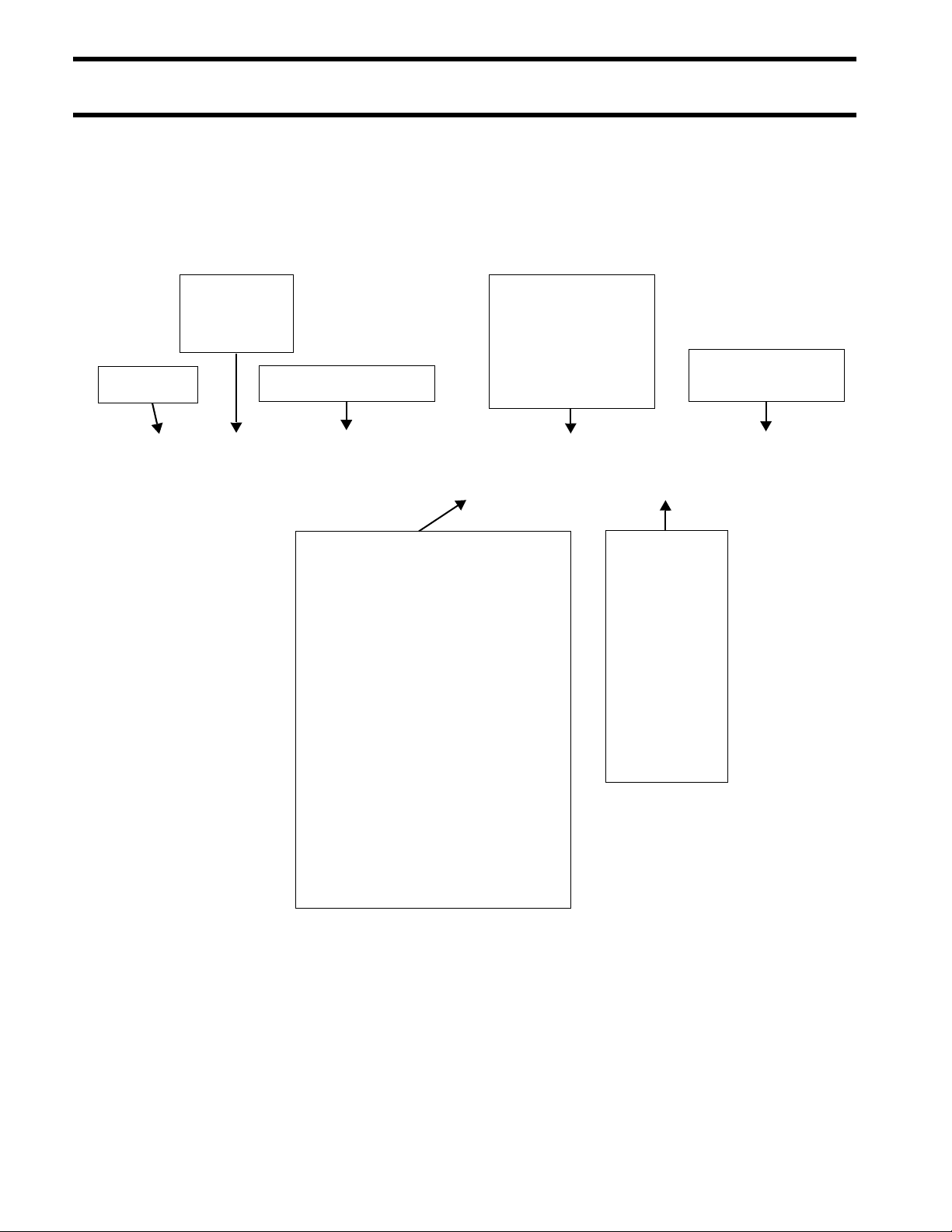
MODEL DESIGNATION
PREFIX
STYLE:
J = Johnson
E = Evinrude
HORSEPOWER
LENGTH:
= 15” Std.
L = 20” Long
Y = 22.5” Special
X = 25” X-long
Z = 30” XX-long
MODEL RUN
or SUFFIX
B E 200 DP X SC A
DESIGN FEATURES:
AP = Advanced Propulsion
B = Blue Paint
C = Counter Rotation
D = Evinrude E-TEC™
E = Electric Start w/Remote Steering
F = Direct-Injection
G = Graphite Paint
H = High Output
J = Jet Drive
M = Military
P = Power Trim and Tilt
R = Rope Start w/Tiller Steering
S = Saltwater Edition
T = Tiller Steering
TE = Tiller Electric
V = White Paint
W = Commercial Model
MODEL YR:
I= 1
N= 2
T= 3
R= 4
O= 5
D= 6
U= 7
C= 8
E= 9
S= 0
Ex: SC = 2008
8
INTRODUCTION
MODELS COVERED IN THIS MANUAL
MODELS COVERED IN
THIS MANUAL
This manual covers service information on all 79
®
cubic inch, 3-Cylinder Evinrude E-TEC
Model Number Shaft Color Gearcase
E75DPLSCB 20” BL “S”
E75DSLSCS 20” WH “S”
E90DPLSCB 20” BL “S”
E90DSLSCM 20” WH “S”
E90DPXSCB 25” WH “O”
E90WDELSCS 20” BL “S”
E90WDEXSCS 25” WH “O”
models.
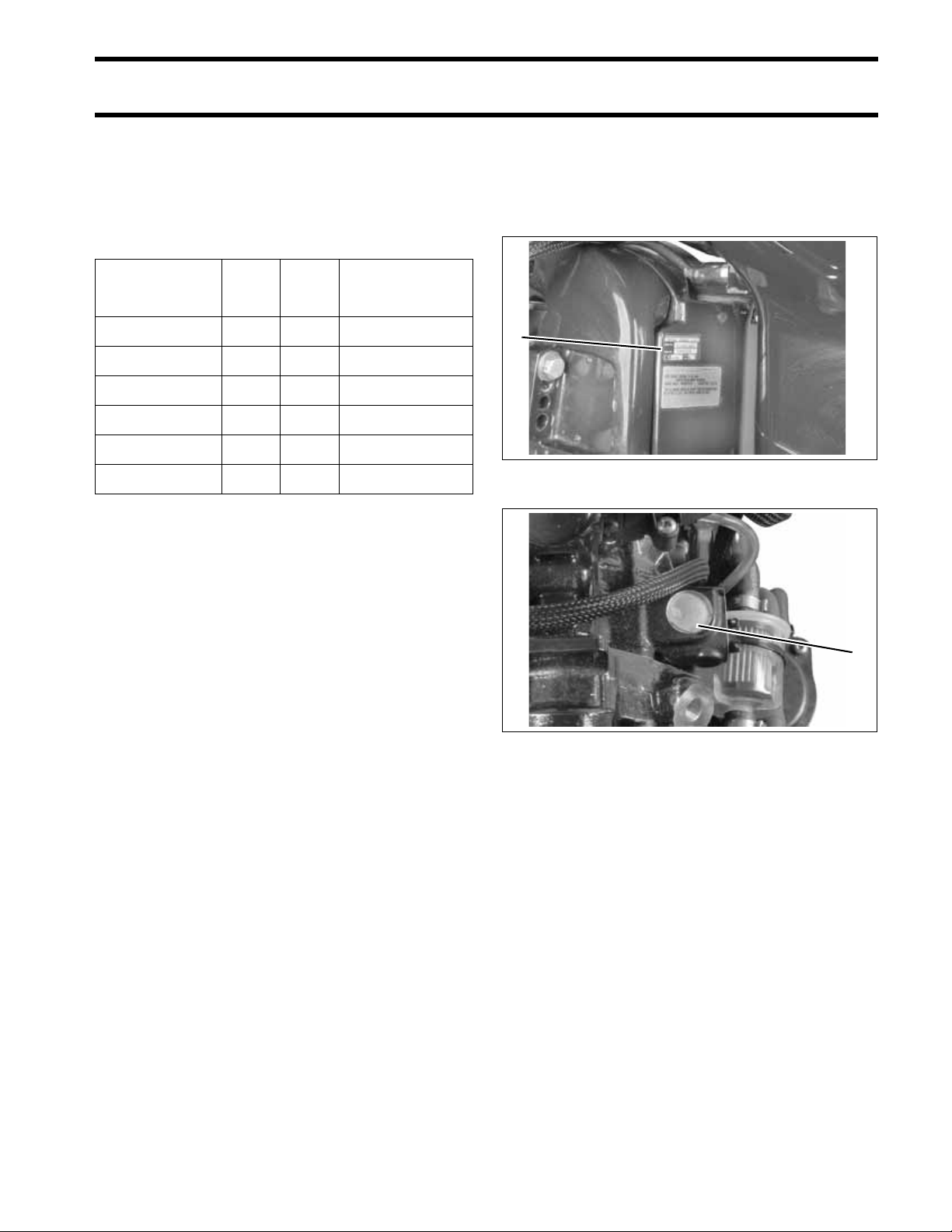
Identifying Model and Serial Numbers
Outboard model and serial numbers are located
on the swivel bracket and on the powerhead.
1
1. Model and serial number 002147
1
1. Serial number 002226
9

INTRODUCTION
SERVICE SPECIFICATIONS
SERVICE SPECIFICATIONS
75 – 90 HP E-TEC Models
Full Throttle
Operating Range RPM
Power
Idle RPM in Gear 700 ± 50 EMM Controlled
Idle RPM in Neutral 600 ± 50 EMM Controlled
Test Propeller
Weight
(may vary depending
on model)
Lubrication
ENGINE
Minimum (High) Fuel Pressure 24 to 28 psi (165 to 193 kPa)
Maximum Fuel Inlet Vacuum 4 in. Hg.
FUEL
Engine Type In-line, 3 Cylinder, T wo-Cycle
Displacement 79.1 cu. in. (1296 cc)
Bore 3.601 in (91.47 mm)
Stroke 2.588 in. (65.74 mm)
Standard Bore
Top Crankshaft Journal 2.1870 to 2.1875 in. (55.55 to 55.56 mm)
Center Crankshaft Journa l s 2.1870 to 2.1875 in. (55.55 to 55.56 m m)
Bottom Crankshaft Journal 1.5747 to 1.5752 in. (40.0 to 40.01 mm)
Rod Crankpin 1.3757 to 1.3762 in. (34.94 to 34.96 mm)
Piston Ring End Gap, Both 0.011 to 0.0 23 in. (0.28 to 0.58 mm)
Fuel/Oil Control EMM Controlled
Starting Enrichment EMM Controlled
Minimum Fuel Lift
Pump Pressure
Minimum Octane 87 AKI (R+M)/2 or 90 RON
Additives
To bore oversize, add piston oversize dimension to standard bore
See Fuel Requirements on p. 51 for additional information
Evinrude/Johnson XD100, XD50, XD30; or
3.6005 to 3.6015 in. (91.45 to 91.48 mm)
2+4 ® Fuel Conditioner, Fuel System Cleaner
Use of other additives may result in engine damage.
4500 to 5500 RPM
75 HP (56 kw) @ 5000 RPM
90 HP (67.1 kw) @ 5000 RPM
(L) Models: P/N 386246
(X) Models: P/N 387388
(L) Models: 320 lbs. (145 kg)
(X) Models: 335 lbs. (152 kg)
NMMA TC-W3 certified
3 psi (21 kPa)
10

75 – 90 HP E-TEC Models
Minimum Battery
Requirements
Alternator 25-Amp fully regulated
Tachometer Setting 6 pulse (12 pole)
ELECTRICAL
Engine Fuse P/N 967545 – 10 A
Maximum Temperature 212°F (100°C)
Thermostat 143°F (62°C)
640 CCA (800 MCA) or 800 CCA (1000 MCA) below 32° F (0° C)
INTRODUCTION
SERVICE SPECIFICATIONS
COOLING
Crankshaft Position Sensor Air
IGNITION
GEARCASE
Water pressure 16 psi minimum @ 5000 RPM
Type Capacitor Discharge
Firing Order 1-2-3
Ignition Timing EMM Controlled
RPM Limit in Gear 6250
RPM Limit in Neutral 1800
Gap
Spark Plug
Gear Ratio
Lubricant HPF XR Gearcase Lube
Capacity
Shift Rod Height
Shift Cable Stroke 1.125 to 1.330 in. (28.6 to 33.8 mm) measured between NEUTRAL and FORWARD
Lubrication Single Piston System–Evinrude/Johnson Biodegradable TNT Fluid
Fluid Capacity 21 fl. oz. (620 ml)
20 in. (L) Models: 13:26 (.500)
25 in. (X) Models: 12:27 (.444)
Refer to Emission Control Information Label
†
Champion
20 in. (L) Models: 21.25 (539.75 mm) ± one-half turn
25 in. (X) Models: 26.25 (666.75 mm) ± one-half turn
QC10WEP @ 0.028 ± .003 in. (0.71 mm)
20 in. (L) Models: 31.6 fl. oz. (935 ml)
25 in. (X) Models: 32.8 fl. oz. (970 ml)
Fixed
2:1
2.25:1
Trim Range 0° to 15°
Tilt Range 16° to 65°
POWER TRIM/TILT
11
INTRODUCTION
STANDARD TORQUE SPECIFICATIONS
STANDARD TORQUE
SPECIFICATIONS
Size In. Lbs. Ft. Lbs. N·m
No. 6 7–10 0.58–0.83 0.8–1.1
No. 8 15–22 1.25–1.83 1.7–2.5
No. 10 24–36 2–3 2.7–4.0
No. 12 36–48 3–4 4.0–5.4
1/4 in. 60–84 5–7 7-9.5
5/16 in. 120–144 10–12 13.5–16.5
3/8 in. 216–240 18–20 24.5–27
7/16 in. 336–384 28–32 38–43.5
IMPORTANT: These values apply only when
a specific torque for a specific fastener is not
listed in the appropriate section. When tightening two or more screws on the same part, DO
NOT tighten screws completely, one at a time.
WARNING
PRODUCT REFERENCE AND ILLUSTRATIONS
BRP US Inc. reserves the right to make changes
at any time, without notice, in specifications and
models and also to discontinue models. The right
is also reserved to change any specifications or
parts, at any time, without incurring any obligation
to equip same on models manufactured prior to
date of such change. Specifications used are
based on the latest product information available
at the time of publication.
The continuing accuracy of this manual cannot be
guaranteed.
All photographs and illustrations used in this manual may not depict actual models or equipment,
but are intended as representative views for reference only.
Certain features or systems discussed in this
manual might not be found on all models in all
marketing areas.
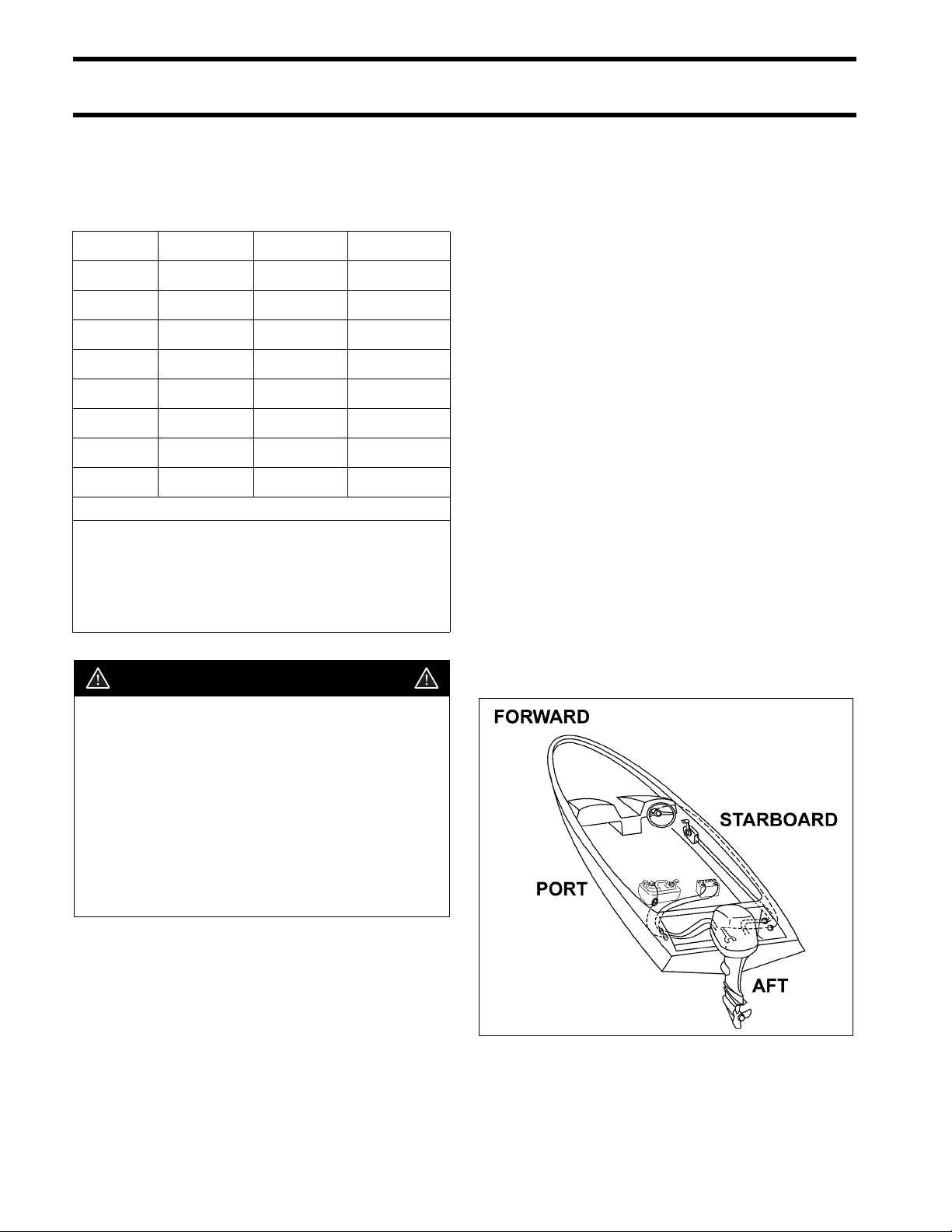
All service technicians must be familiar with nautical orientation. This manual often identifies parts
and procedures using these terms.
Torque wrench tightening specifications
must be strictly adhered to. Replace any
locking fastener (locknut or patch screw)
if its locking feature becomes weak. Definite resistance to turning must be felt
when reusing a locking fastener.
If replacement is specified or required
because the locking fastener has become
weak, use only authorized Evinrude/
Johnson Genuine Parts.
Nautical Orientation 006411
12

SPECIAL TOOLS
SPECIAL TOOLS
TABLE OF CONTENTS
DIAGNOSTIC TOOLS . . . . . . . . . . . . . . . . . . . . . . . . . . . . . . . . . . . . . . . . . . . . . . . . . . . . . . . . . . . . . . . .14
UNIVERSAL TOOLS . . . . . . . . . . . . . . . . . . . . . . . . . . . . . . . . . . . . . . . . . . . . . . . . . . . . . . . . . . . . . . . . .14
ELECTRICAL / IGNITION TOOLS . . . . . . . . . . . . . . . . . . . . . . . . . . . . . . . . . . . . . . . . . . . . . . . . . . . . . . .16
FUEL /OIL SYSTEM TOOLS . . . . . . . . . . . . . . . . . . . . . . . . . . . . . . . . . . . . . . . . . . . . . . . . . . . . . . . . . . .17
POWERHEAD TOOLS . . . . . . . . . . . . . . . . . . . . . . . . . . . . . . . . . . . . . . . . . . . . . . . . . . . . . . . . . . . . . . . .17
GEARCASE TOOLS . . . . . . . . . . . . . . . . . . . . . . . . . . . . . . . . . . . . . . . . . . . . . . . . . . . . . . . . . . . . . . . . . 18
TRIM AND TILT TOOLS . . . . . . . . . . . . . . . . . . . . . . . . . . . . . . . . . . . . . . . . . . . . . . . . . . . . . . . . . . . . . .20
SHOP AIDS . . . . . . . . . . . . . . . . . . . . . . . . . . . . . . . . . . . . . . . . . . . . . . . . . . . . . . . . . . . . . . . . . . . . . . . .21
NOTES . . . . . . . . . . . . . . . . . . . . . . . . . . . . . . . . . . . . . . . . . . . . . . . . . . . . . . . . . . . . . . . . . . . . . . . . . . . .24
1
13
SPECIAL TOOLS
DIAGNOSTIC TOOLS
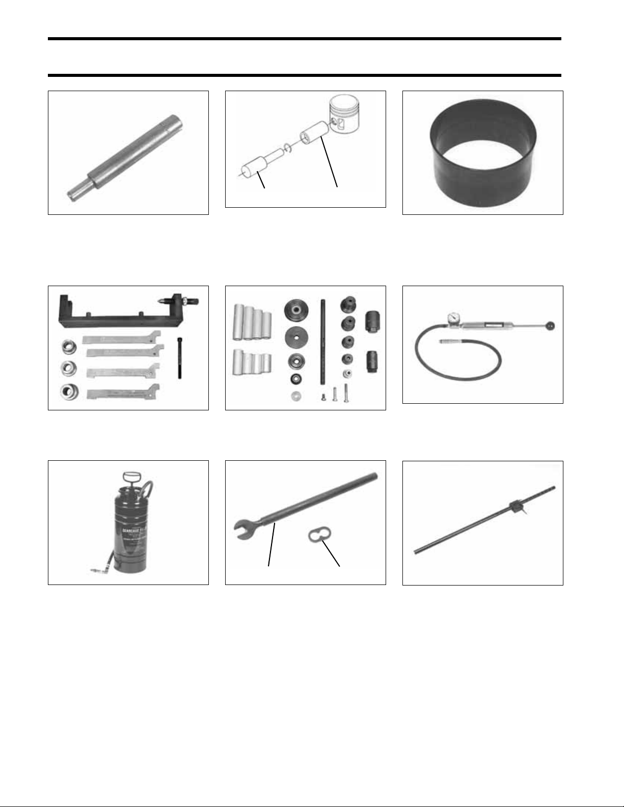
DIAGNOSTIC TOOLS
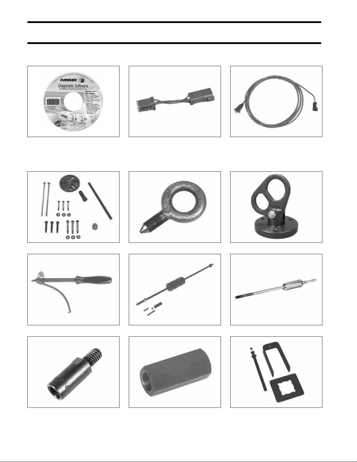
Diagnostic Software P/N 764642 764642 Bootstrap tool P/N 586551 002276 Interface cable P/N 437955 45583
UNIVERSAL TOOLS
Universal Puller Set P/N 378103 32885
Flywheel holder P/N 771311 42938
Slide hammer adapter P/N 340624 39435
Lifting eye P/N 321537 23701
Slide hammer P/N 391008 CO1577
Slide hammer adapter P/N 390898 15356
Lifting ring assembly P/N 396748 000669
Slide hammer P/N 432128 15345
Puller Bridge – 432127 23146
14
SPECIAL TOOLS
UNIVERSAL TOOLS
1
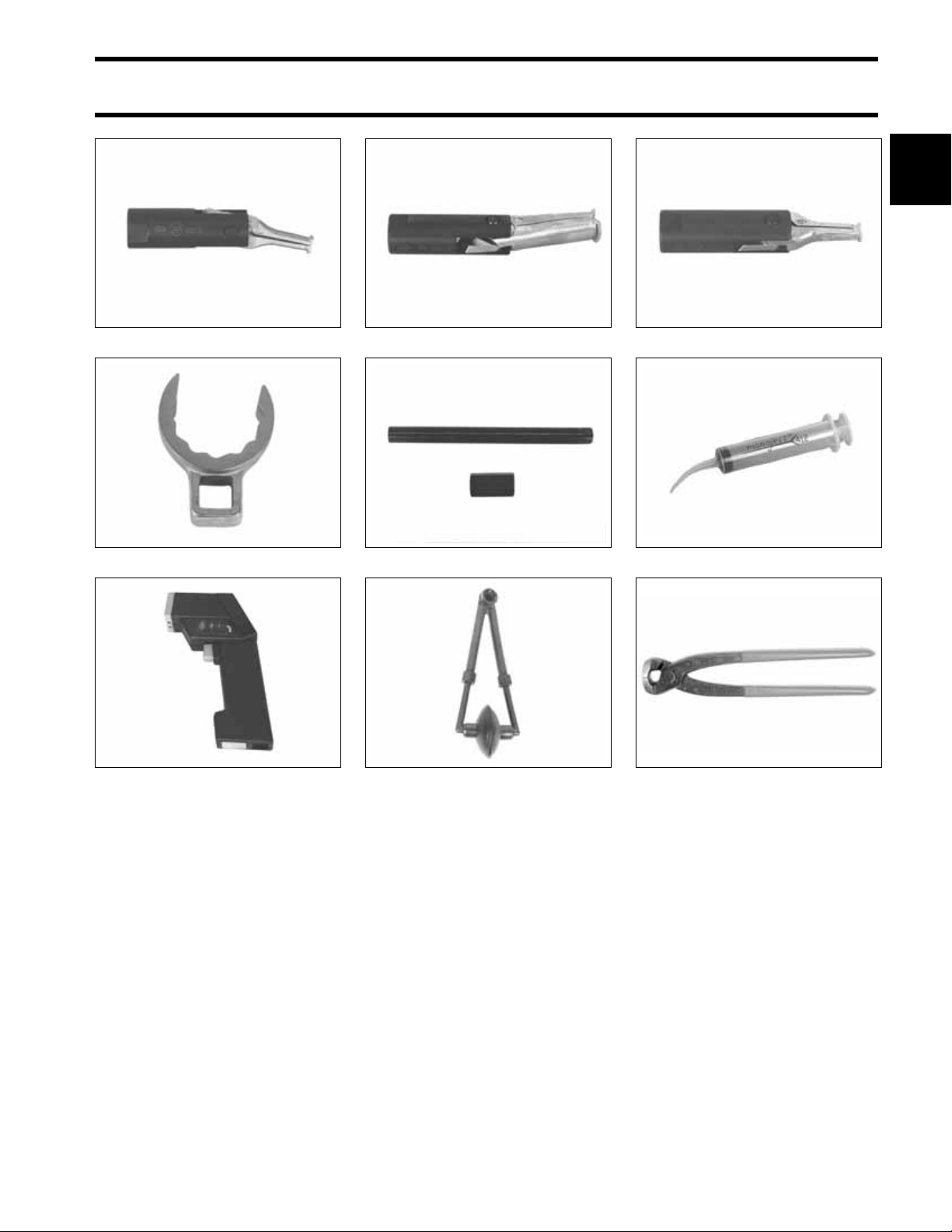
Small puller jaws P/N 432131 23150
Tilt tube nut wrench P/N 342680 46879
Temperature gun P/N 772018 45240
Large puller jaws P/N 432129 23148
Tilt tube service kit P/N 434523 33249
Fresh water flusher P/N 500542 50110
Bearing puller jaws P/N 432130 23149
Syringe P/N 346936 50243
†
pincers, P/N 787145
Oetiker
001081
15
SPECIAL TOOLS
ELECTRICAL / IGNITION TOOLS
ELECTRICAL / IGNITION TOOLS
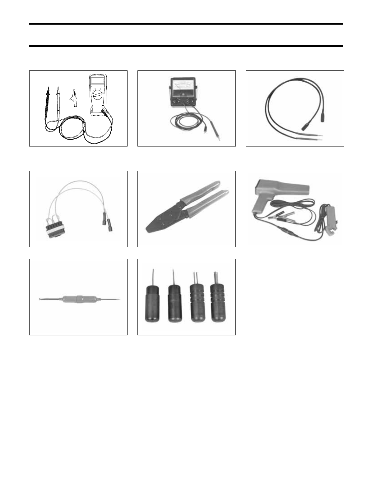
Digital multimeter
Ohms resolution 0.01
Purchase through local supplier
Stator Test Adapter P/N 5005799 002273
DRC7265
Peak reading voltmeter
P/N 507972
Crimping pliers P/N 322696 30387
49799
Test probe kit P/N 342677 45241
Tachometer/timing light P/N 507980 49789
Connector tool P/N 342667 42004
16
†
connector tools
AMP
Primary Lock Tool P/N 777077
Secondary Lock Tool P/N 777078
Release Tool P/N 351413
Lock Installer P/N 777079
002277
FUEL /OIL SYSTEM TOOLS
SPECIAL TOOLS
FUEL /OIL SYSTEM TOOLS
1
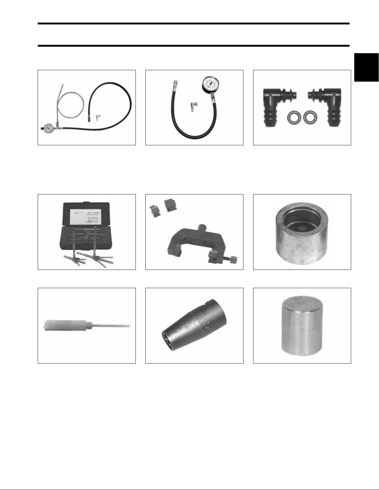
Fuel pressure gauge (60 PSI)
P/N 5007100
90° fitting, P/N 353322
005339
Fuel pressure gauge (15 PSI)
P/N 5006397
90° fitting, P/N 353322
POWERHEAD TOOLS
Cylinder bore gauge P/N 771310 45303
Rod cap alignment fixture
P/N 396749
004560
21596
Injector test fitting kit
P/N 5005844
Crankshaft bearing and sleeve
installer P/N 338647
002465
21953B
Piston stop tool P/N 342679
Replacement tip P/N 5006098
46543
Torquing socket P/N 331638 000797
Wrist pin bearing installer
P/N 336660
41029
17
SPECIAL TOOLS
GEARCASE TOOLS
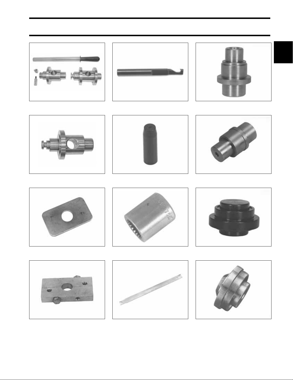
1 2
Wrist pin pressing tool
P/N 326356
23668
1. Wrist pin retaining ring driver
2. Wrist pin cone P/N 318600
GEARCASE TOOLS
P/N 318599
DR1641
Ring compressor – standard
·P/N 336314
CO3768
Universal Driveshaft Shimming Tool
P/N 5005925
1. Lower Driveshaft Shimming Bolt
(S2 gearcase) P/N352878
Gearcase filler
P/N 501882
1
002601
49790
Universal Pinion Bearing Remover
and installer kit P/N 5005927
1 2
1. Pinion nut holder P/N 334455
2. Wrench retainer P/N 341438
002805
40371
Gearcase pressure tester
P/N 507977 (Stevens P/N S-34)
Gearcase vacuum tester
P/N 507982 (Stevens P/N V-34)
Universal shift rod height gauge
P/N 389997
49794
32872
18
SPECIAL TOOLS
GEARCASE TOOLS
1
Gearcase Alignment Gauge Kit
P/N 5006349
Gauging Head, “S” Type
Gearcases, P/N 352879
004315
005072
Lower Driveshaft Puller P/N 342681 47257
Driveshaft seal protector
P/N 318674
23692
Bearing Installer P/N 326562 32962
Prop shaft bearing installer
P/N 339750
32880
Backing plate P/N 325867 23621
Driveshaft Puller P/N 390706 32884
Driveshaft socket P/N 311875 23261
Pinion nut starting tool P/N 342216 40372
Prop shaft housing seal installer
P/N 326551, P/N 336311
Seal installation tool P/N 330268 32924
32973
19
SPECIAL TOOLS
TRIM AND TILT TOOLS
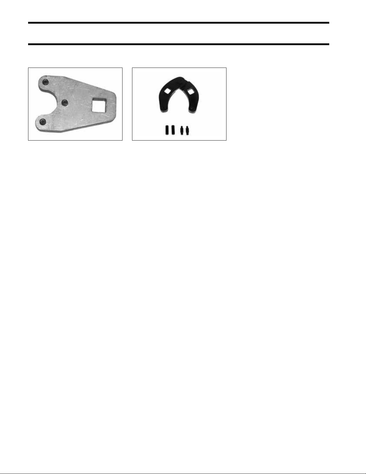
TRIM AND TILT TOOLS
Tilt cylinder end cap remover
P/N 352932, for single-piston
tilt systems
005340
Spanner wrench P/N 912084 32213
20

SHOP AIDS
SPECIAL TOOLS
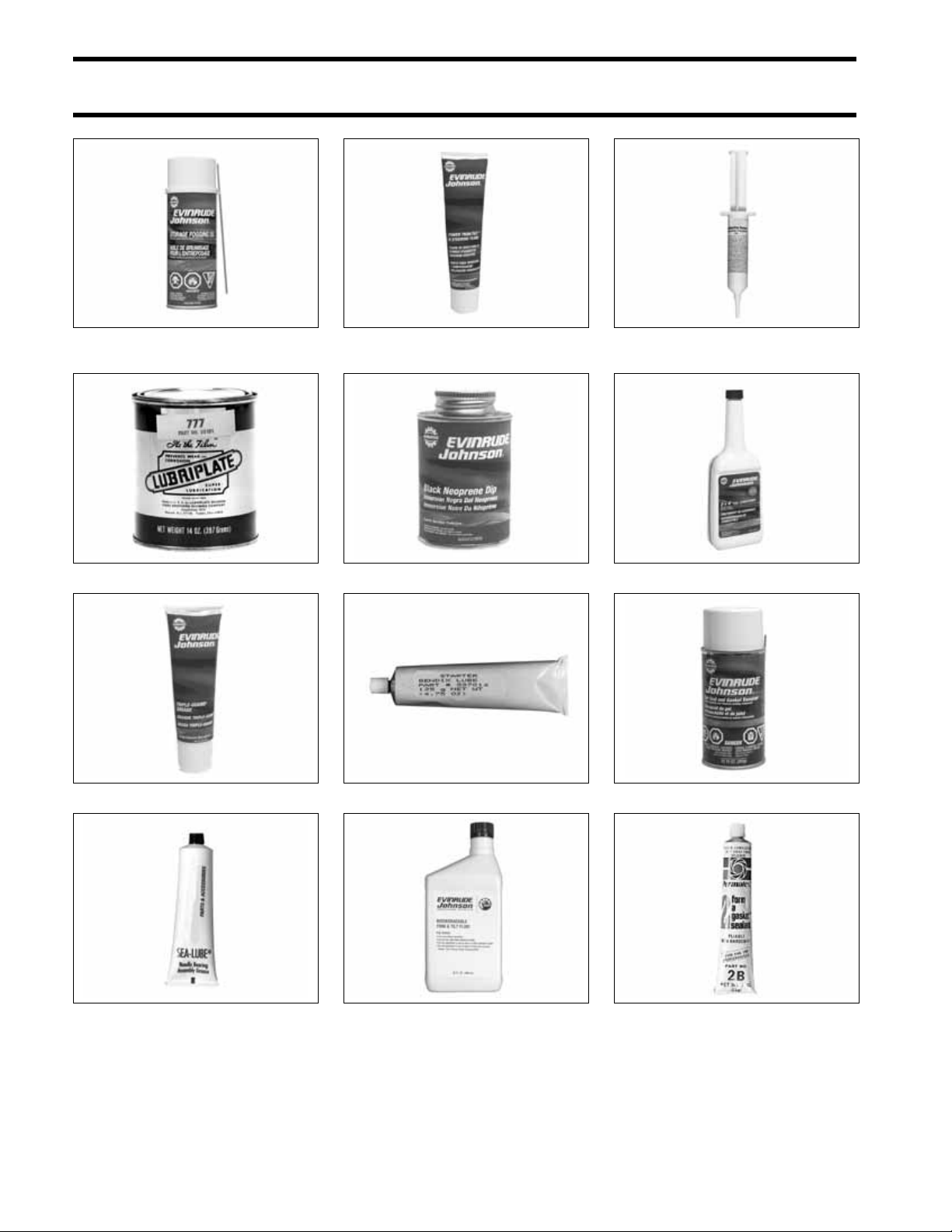
SHOP AIDS
1
Cleaning Solvent P/N 771087
“6 in 1” Multi-Purpose Lubricant P/N 777192
Oil - XD100™ P/N 777118
D.P.L. Spray P/N 777183
Oil - XD50™ P/N 777225
Anti-Corrosion Spray P/N 777193
Oil - XD30™ P/N 777219
HPF XR™ Gear Lube P/N 778755
HPF PRO Gearcase Lube P/N 778755
Engine Tuner P/N 777185
Silicone spray P/N 775630
Moly Lube P/N 175356
21
SPECIAL TOOLS
SHOP AIDS
Storage Fogging Oil
P/N 777186
Lubriplate† 777 P/N 317619
Power Trim/Tilt and Power Steering Fluid
P/N 775612
Black Neoprene Dip P/N 909570
Electrical Grease P/N 503243
2 + 4™ Fuel conditioner P/N 775613
Triple-Guard® Grease P/N 508298
Needle Bearing Grease, P/N 378642
22
Starter Bendix Lube P/N 337016
Biodegradeable TNT Fluid
P/N 763439
Gel-Seal and Gasket Remover P/N 771050
†
Permatex
No. 2, P/N 910032

SPECIAL TOOLS
SHOP AIDS
1
RTV Silicone Sealant P/N 263753
Fuel System Cleaner P/N 777184
Gel·Seal II P/N 327361
Gasket Sealing Compound P/N 317201
Pipe Sealant with Teflon P/N 910048
Locquic Primer P/N 772032
Thermal Joint Compound P/N 322170
Instant Bonding Adhesive P/N 509955
1 2 3
1. Screw Lock P/N 500417
2. Nut Lock P/N 500421
3. Ultra Lock P/N 500423
†
Purple 222 equivalent
(Loctite
(Loctite Blue 242 Equivalent)
(Loctite Red 271 Equivalent)
Carbon Guard™ P/N 775629
Adhesive 847 P/N 776964
23

SPECIAL TOOLS
NOTES
NOTES
Technician’s Notes Related Documents
Bulletins
Instruction Sheets
Other
24

INSTALLATION AND PREDELIVERY
INSTALLATION AND PREDELIVERY
TABLE OF CONTENTS
BOAT RIGGING . . . . . . . . . . . . . . . . . . . . . . . . . . . . . . . . . . . . . . . . . . . . . . . . . . . . . . . . . . . . . . . . . . . . .26
REMOTE CONTROLS . . . . . . . . . . . . . . . . . . . . . . . . . . . . . . . . . . . . . . . . . . . . . . . . . . . . . . . . . . . . . . . 26
BATTERY INSTALLATION . . . . . . . . . . . . . . . . . . . . . . . . . . . . . . . . . . . . . . . . . . . . . . . . . . . . . . . . . . . . 27
BATTERY SWITCHES AND MULTIPLE BATTERIES . . . . . . . . . . . . . . . . . . . . . . . . . . . . . . . . . . . . . . . . . .28
BATTERY AND SWITCH WIRING DIAGRAMS . . . . . . . . . . . . . . . . . . . . . . . . . . . . . . . . . . . . . . . . . . . . . .30
FUEL SYSTEM REQUIREMENTS . . . . . . . . . . . . . . . . . . . . . . . . . . . . . . . . . . . . . . . . . . . . . . . . . . . . . . .32
CABLE AND HOSE INSTALLATION . . . . . . . . . . . . . . . . . . . . . . . . . . . . . . . . . . . . . . . . . . . . . . . . . . . . .34
OUTBOARD INSTALLATION . . . . . . . . . . . . . . . . . . . . . . . . . . . . . . . . . . . . . . . . . . . . . . . . . . . . . . . . . .38
HULL PREPARATION . . . . . . . . . . . . . . . . . . . . . . . . . . . . . . . . . . . . . . . . . . . . . . . . . . . . . . . . . . . . . . .38
TRANSOM MEASURING AND DRILLING . . . . . . . . . . . . . . . . . . . . . . . . . . . . . . . . . . . . . . . . . . . . . . . . . . 40
LIFTING THE OUTBOARD . . . . . . . . . . . . . . . . . . . . . . . . . . . . . . . . . . . . . . . . . . . . . . . . . . . . . . . . . . . .43
STEERING SYSTEMS . . . . . . . . . . . . . . . . . . . . . . . . . . . . . . . . . . . . . . . . . . . . . . . . . . . . . . . . . . . . . . . 43
OUTBOARD MOUNTING . . . . . . . . . . . . . . . . . . . . . . . . . . . . . . . . . . . . . . . . . . . . . . . . . . . . . . . . . . . . .45
OUTBOARD RIGGING . . . . . . . . . . . . . . . . . . . . . . . . . . . . . . . . . . . . . . . . . . . . . . . . . . . . . . . . . . . . . . . .46
CABLE, HOSE, AND WIRE ROUTING . . . . . . . . . . . . . . . . . . . . . . . . . . . . . . . . . . . . . . . . . . . . . . . . . . . . 46
CONTROL CABLE ADJUSTMENTS . . . . . . . . . . . . . . . . . . . . . . . . . . . . . . . . . . . . . . . . . . . . . . . . . . . . .46
ELECTRICAL HARNESS CONNECTIONS . . . . . . . . . . . . . . . . . . . . . . . . . . . . . . . . . . . . . . . . . . . . . . . . . 48
WATER PRESSURE GAUGE . . . . . . . . . . . . . . . . . . . . . . . . . . . . . . . . . . . . . . . . . . . . . . . . . . . . . . . . . .48
CANBUS CONNECTIONS . . . . . . . . . . . . . . . . . . . . . . . . . . . . . . . . . . . . . . . . . . . . . . . . . . . . . . . . . . . .49
FUEL AND OIL PRIMING . . . . . . . . . . . . . . . . . . . . . . . . . . . . . . . . . . . . . . . . . . . . . . . . . . . . . . . . . . . . .51
FUEL REQUIREMENTS . . . . . . . . . . . . . . . . . . . . . . . . . . . . . . . . . . . . . . . . . . . . . . . . . . . . . . . . . . . . . .51
FUEL SYSTEM PRIMING . . . . . . . . . . . . . . . . . . . . . . . . . . . . . . . . . . . . . . . . . . . . . . . . . . . . . . . . . . . . .52
OIL REQUIREMENTS . . . . . . . . . . . . . . . . . . . . . . . . . . . . . . . . . . . . . . . . . . . . . . . . . . . . . . . . . . . . . . .52
OIL INJECTION RATE . . . . . . . . . . . . . . . . . . . . . . . . . . . . . . . . . . . . . . . . . . . . . . . . . . . . . . . . . . . . . . .53
BREAK-IN OILING . . . . . . . . . . . . . . . . . . . . . . . . . . . . . . . . . . . . . . . . . . . . . . . . . . . . . . . . . . . . . . . . . 54
OIL SUPPLY PRIMING . . . . . . . . . . . . . . . . . . . . . . . . . . . . . . . . . . . . . . . . . . . . . . . . . . . . . . . . . . . . . .54
BEFORE START-UP . . . . . . . . . . . . . . . . . . . . . . . . . . . . . . . . . . . . . . . . . . . . . . . . . . . . . . . . . . . . . . . . .55
RUNNING CHECKS . . . . . . . . . . . . . . . . . . . . . . . . . . . . . . . . . . . . . . . . . . . . . . . . . . . . . . . . . . . . . . . . . .56
ENGINE MONITORING SYSTEM . . . . . . . . . . . . . . . . . . . . . . . . . . . . . . . . . . . . . . . . . . . . . . . . . . . . . . . . 56
FUEL SYSTEM . . . . . . . . . . . . . . . . . . . . . . . . . . . . . . . . . . . . . . . . . . . . . . . . . . . . . . . . . . . . . . . . . . . .56
EMERGENCY STOP / KEY SWITCH . . . . . . . . . . . . . . . . . . . . . . . . . . . . . . . . . . . . . . . . . . . . . . . . . . . . . 56
REMOTE CONTROL OPERATION . . . . . . . . . . . . . . . . . . . . . . . . . . . . . . . . . . . . . . . . . . . . . . . . . . . . . . 56
START-IN-GEAR PREVENTION . . . . . . . . . . . . . . . . . . . . . . . . . . . . . . . . . . . . . . . . . . . . . . . . . . . . . . . . 56
TACHOMETER PULSE SETTING . . . . . . . . . . . . . . . . . . . . . . . . . . . . . . . . . . . . . . . . . . . . . . . . . . . . . . .56
WATER PUMP OVERBOARD INDICATOR . . . . . . . . . . . . . . . . . . . . . . . . . . . . . . . . . . . . . . . . . . . . . . . . .57
PROPELLERS . . . . . . . . . . . . . . . . . . . . . . . . . . . . . . . . . . . . . . . . . . . . . . . . . . . . . . . . . . . . . . . . . . . . . .58
PROPELLER SELECTION . . . . . . . . . . . . . . . . . . . . . . . . . . . . . . . . . . . . . . . . . . . . . . . . . . . . . . . . . . . .58
PROPELLER HARDWARE INSTALLATION . . . . . . . . . . . . . . . . . . . . . . . . . . . . . . . . . . . . . . . . . . . . . . . .59
FINAL ADJUSTMENTS . . . . . . . . . . . . . . . . . . . . . . . . . . . . . . . . . . . . . . . . . . . . . . . . . . . . . . . . . . . . . . .60
TILT LIMIT SWITCH ADJUSTMENT . . . . . . . . . . . . . . . . . . . . . . . . . . . . . . . . . . . . . . . . . . . . . . . . . . . . . .60
TRIM SENDING UNIT ADJUSTMENT . . . . . . . . . . . . . . . . . . . . . . . . . . . . . . . . . . . . . . . . . . . . . . . . . . . .61
TRIM TAB ADJUSTMENT . . . . . . . . . . . . . . . . . . . . . . . . . . . . . . . . . . . . . . . . . . . . . . . . . . . . . . . . . . . .62
DUAL-OUTBOARD ALIGNMENT . . . . . . . . . . . . . . . . . . . . . . . . . . . . . . . . . . . . . . . . . . . . . . . . . . . . . . .63
NOTES . . . . . . . . . . . . . . . . . . . . . . . . . . . . . . . . . . . . . . . . . . . . . . . . . . . . . . . . . . . . . . . . . . . . . . . . . . . .64
2
25
INSTALLATION AND PREDELIVERY
BOAT RIGGING
BOAT RIGGING
Remote Controls
Control Selection
WARNING
The remote control used must have startin-gear prevention. This feature can prevent injuries resulting from unexpected
boat movement when the outboard starts.
Remote control and wiring harness options are
described in the Evinrude/Johnson Genuine Parts
and Accessories Catalog.
The remote control and wiring harness combination must have the following features:
• Start-in-gear prevention
• Emergency stop / key switch
• Shift stroke must measure 1.125 to 1.330 in.
(28.6 to 33.8 mm) between NEUTRAL and
FORWARD
• Throttle stroke must PUSH for open
• Connections for engine monitor warning sys-
tem.
• Dual-outboard controls require separate key
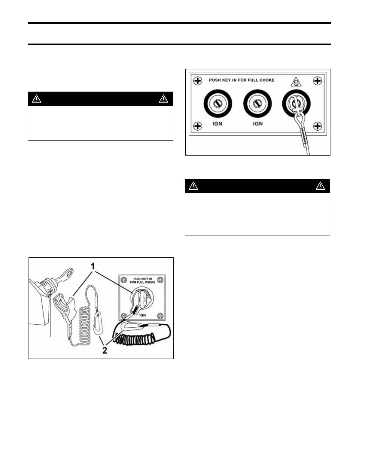
switches with a single emergency stop switch.
Dual-outboard key switches with emergency stop
switch
DRC40118
WARNING
Always install and recommend use of an
emergency stop/key switch. Doing so will
reduce the risk of personal injury or death
should the operator fall away from the controls or out of the boat.
Engine Monitoring System
3
1. Emergency stop clip
2. Safety lanyard
3. Key switch with emergency stop feature
IMPORTANT: Outboards with remote controls
must be equipped with an I-Command system, a
SystemCheck gauge, or an equivalent engine
monitor. Operating the out board without an engine
monitor will void the warranty for failures related to
monitored functions.
Refer to ENGINE MONITORING SYSTEM on
p. 93.
002817
26
INSTALLATION AND PREDELIVERY
BOAT RIGGING
Control Installation
Plan the installation of remote controls carefully,
following all instructions provided with the remote
control.
Make sure the following items are checked:
• Correct length, type and quality of control
cables and wiring harnesses
• Proper routing of cables and harnesses
• Slack in front of the outboard for remote control
cables
• Positioning and securing of cables and har-
nesses along their lengths to prevent movement
or damage.
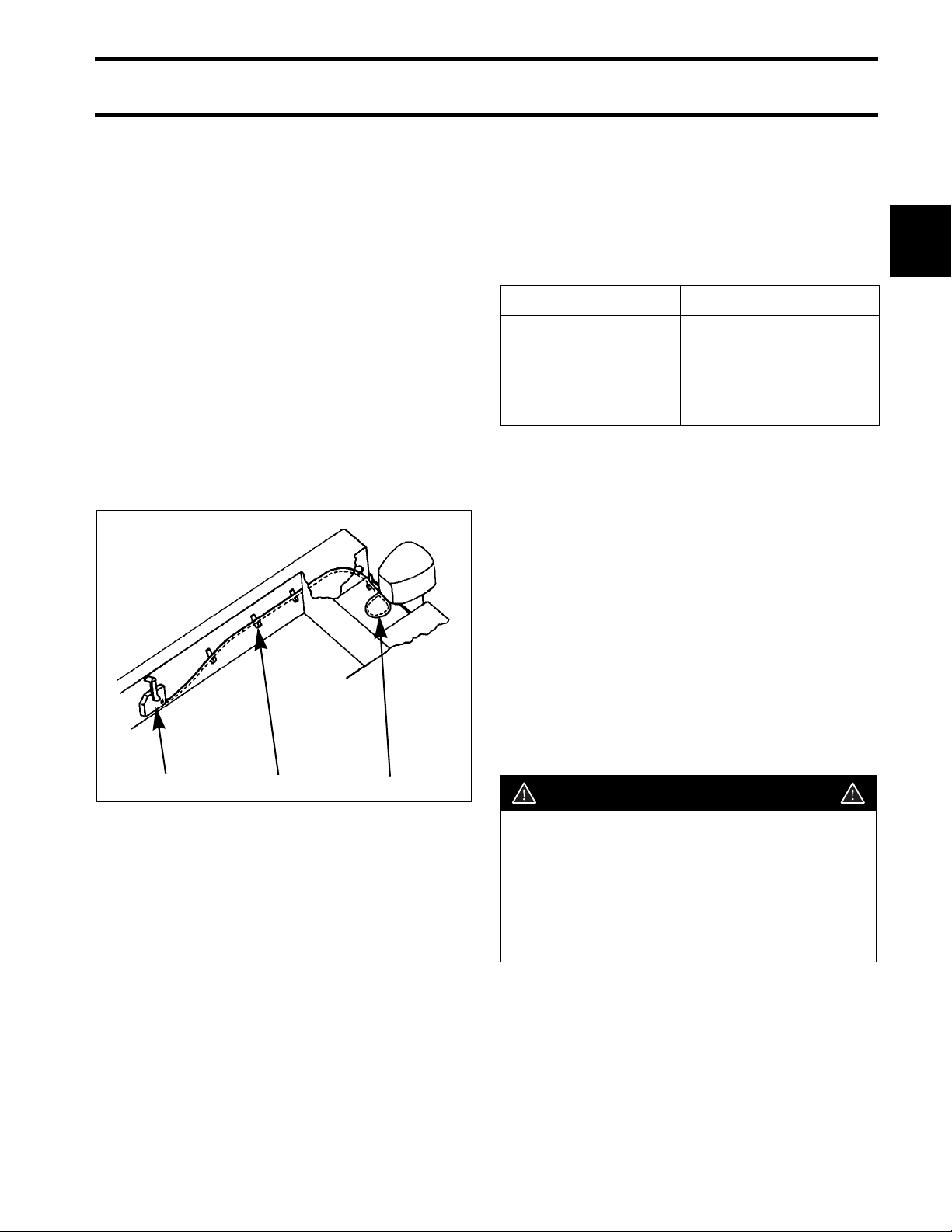
Typical transom-mounted outboard installations
require a 12 in. (30 cm) cable loop at the front of
the outboard when the cables are routed from the
side of the splash well.
Battery Installation
Each outboard requires its own starting battery.
Select a battery that meets or exceeds the minimum requirements.
Minimum 12 Volt Battery
Recommendations
Outboard Model Battery Rating
40–90 HP 640 CCA (800 MCA), or
800 CCA (1000 MCA)
below 32° F (0° C)
107 amp-hr in extreme
applications
Location and Preparation
Proper installation will prevent battery movement
while underway.
• Secure all batteries in protected locations.
• Place battery as close to the outboard as possi-
ble.
• Battery location must provide access for peri-
odic maintenance.
• Use battery mounting trays or battery boxes on
all battery installations.
• Connections and terminals must be covered
with an insulator.
• Battery connections must be clean and free
from corrosion.
• Read and understand the safety information
supplied with the battery before installation.
2
123
1. Surface side-mount remote control
2. Cable support
3. 12 in. (30 cm) cable loop at front of outboard
DR4277
IMPORTANT: Cables of the proper length, style,
and quality that are correctly installed and
adjusted will eliminate most control-related operational problems.
WARNING
Keep the battery connections clean, tight,
and insulated to prevent their shorting or
arcing and causing an explosion. If the battery mounting system does not cover the
connections, install protective covers.
Check often to see that connections stay
clean and tight.
27
INSTALLATION AND PREDELIVERY
BOAT RIGGING
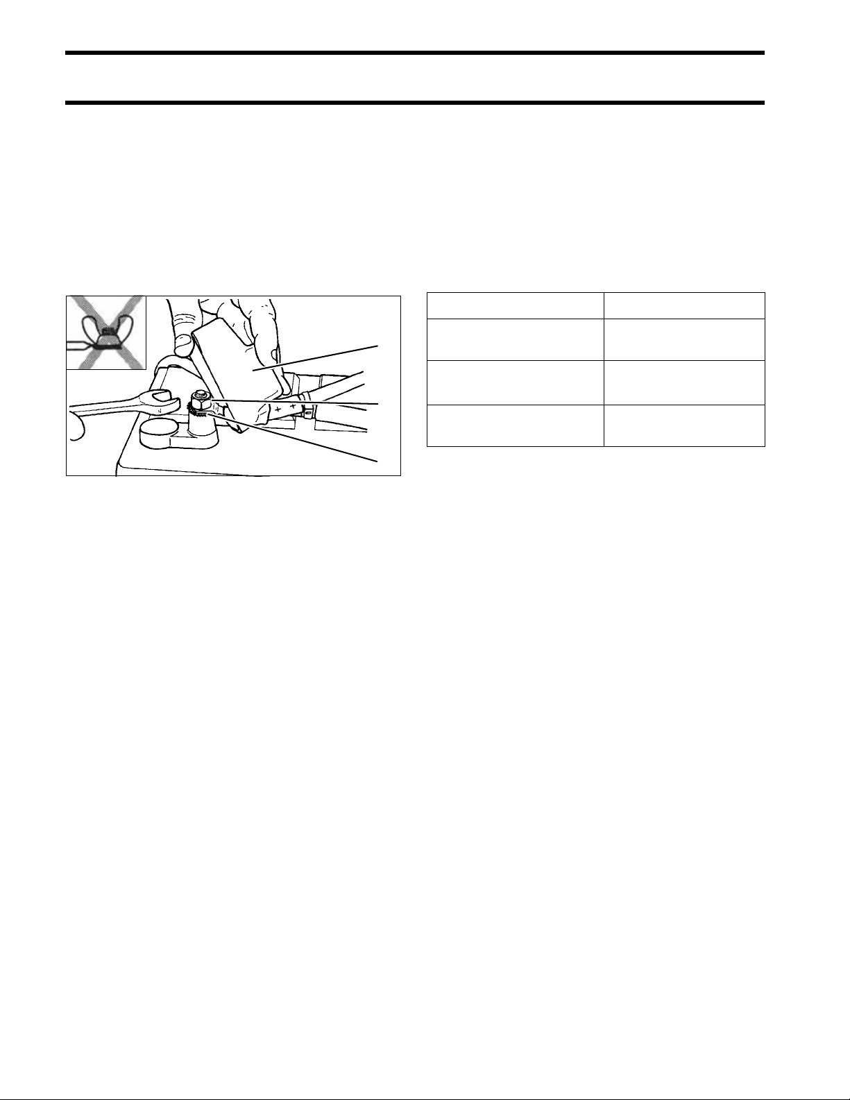
Connections
IMPORTANT: Connect the battery positive (+)
cable to the battery positive (+) post FIRST. Connect the battery negative (–) cable to the battery
negative (–) post LAST.
Install a starwasher on the threaded battery post.
Stack cables from the outboard, then cables from
accessories. Finish this connection with a hex nut.
3
2
1
Marine Style Battery Post
1. Starwasher
2. Hex nut
3. Terminal Insulator
DR5103
IMPORTANT: Do not use wing nuts to fasten
ANY battery cables. Wing nuts can loosen and
cause electrical system damage not covered
under warranty.
Tighten all connections securely. Apply Triple-
Guard grease to prevent corrosion.
Battery Cable Requirements
Evinrude outboards are shipped with stranded
copper battery cables for typical installations in
which the starting battery is positioned close to the
transom.
Specialized outboard installations with extended
length battery cables require an increased wire
size. Refer to the following table.
40–250 HP
1 to 10 Ft.
(.3 to 3 m)
11 to 15 Ft.
(3.4 to 4.6 m)
16 to 20 Ft.
(4.9 to 6.1 m)
4 Gauge
2 Gauge
1 Gauge
IMPORTANT: Inadequate battery cables can
affect the performance of an outboard’s high
amperage start circuit and the cranking speed of
the outboard. DO NOT use aluminum wire cables.
Use ONLY AWG stranded copper wire cables.
Battery Switches and Multiple Batteries
A multiple battery setup, including marine battery
selector switches, can provide flexibility in single
and dual outboard installations.
28
Refer to Battery and Switch Wiring Diagrams
on p. 30 for battery connection options.
The battery selection function can be used for
emergency starting if a primary battery becomes
discharged.
The OFF position of the battery selector switch
can be used to minimize battery discharge during
periods of non-use.
 Loading...