

Page 1
evinci™ ELECTRIC BICYCLE
USER MANUAL
infinity Series
PLEASE READ CAREFULLY
Page 2

Table of Contents
Safety Instructions........................................................................................3
Symbols.......................................................................................................3
Introduction.................................................................................................4
Mode of operation and extent of electronic power assistance..........................................4
Levels of support..........................................................................................................4
What comes with the bike?............................................................................4
Components.................................................................................................5
Basic Safety Tips...........................................................................................5
For your own road safety..............................................................................................6
How to use your charger...............................................................................6
Safety notes concerning the battery...............................................................8
Charging the battery.....................................................................................9
How to remove and insert the battery............................................................................9
Before starting to ride...................................................................................9
Mount or dismount front wheel......................................................................................9
Adjust Seat height......................................................................................................10
How to find the correct saddle height?.........................................................................10
Adjusting the saddle angle..........................................................................................10
Adjust the stem and handlebar....................................................................................11
Check tire pressure.....................................................................................................11
Suspension fork..........................................................................................................11
Operation...................................................................................................12
Display.......................................................................................................................12
Throttle......................................................................................................................13
Gears.........................................................................................................................13
Brakes.......................................................................................................................14
Maintenance...............................................................................................14
Brakes.......................................................................................................................14
Gears.........................................................................................................................14
Safety points..............................................................................................15
Repairing a puncture...................................................................................15
Trouble shooting.........................................................................................16
Glossary.....................................................................................................17
BMS...........................................................................................................................17
Controller...................................................................................................................17
Display.......................................................................................................................17
Hall sensor.................................................................................................................17
Pedal Assist Sensor (PAS)............................................................................................18
Torque Sensor............................................................................................................18
2
Page 3
Safety Instructions
Thank you for purchasing an electric bike from NZEBIKES. Your infinity
mountain bike features the most recent innovation in technology and applies to
the AS/NZ standard. For safety reasons, it is most important that you read this
User Guide BEFORE you operate the bike. Improper handling can reduce its
riding performance and most importantly, pose danger to your safety and
health!
NZEBIKES is continuously updating and innovating this product. The printed
manual may therefore not always include the latest updates. However, we shall
make sure that our online manual will always be up to date on
www.volto.co.nz/support.
We want also encourage you to register your bike with your
frame serial number. This allows us to help you finding your
bike in case of theft, as we get contacted by the police when
bikes are recovered.
To register just go to our Volto website and click on “Login”.
Symbols
Please pay particular attention to information next to one of the symbols shown
below as it can be very important for your personal safety.
WARNING
This symbol indicates that improper handling poses a
risk to your health and safety
ATTENTION
This indicates that improper handling could damage
components and make void the warranty.
NOTE
Points out to useful tips
3
Page 4

Introduction
You have decided in favour of a Pedelec (Pedal Electric Cycle) - a bicycle that is
equipped with an electric motor to give you additional assistance when riding.
With this bicycle you can make better progress in headwinds, when
transporting heavy loads or on steep slopes.
You can select the level of power assistance required according to the weight of
your load and/or the prevailing road conditions, the effectiveness of the power
assistance depends on your pedal power and the level of assistance selected.
Before switching on the electric assistance system, please read the chapter
“Charging the battery”. The battery must be fully charged before you go for a
ride the first time.
Mode of operation and extent of electronic power assistance
As soon as you turn on the electric assistance system and begin pedalling or
pushing the throttle, electronic power assistance is available. Depending on the
selected assistance level the motor will add a certain amount of power to assist
you. The amount of support is also proportional to the force pushed into the
pedals thanks to the torque sensor integrated into the crank axle.
An average rider can easily reach on flat tracks up to 80km out of the standard
13Ah battery.
Levels of support
There are currently five support levels:
1 = 20%, 2 = 40%, 3 = 60%, 4 = 80%, 5 = 100%
With higher support the motor will reach also a higher speed.
What comes with the bike?
• 240V mains charger
An optional 12V charger (Powerbuddy) can be purchased through your retailer.
4
Page 5
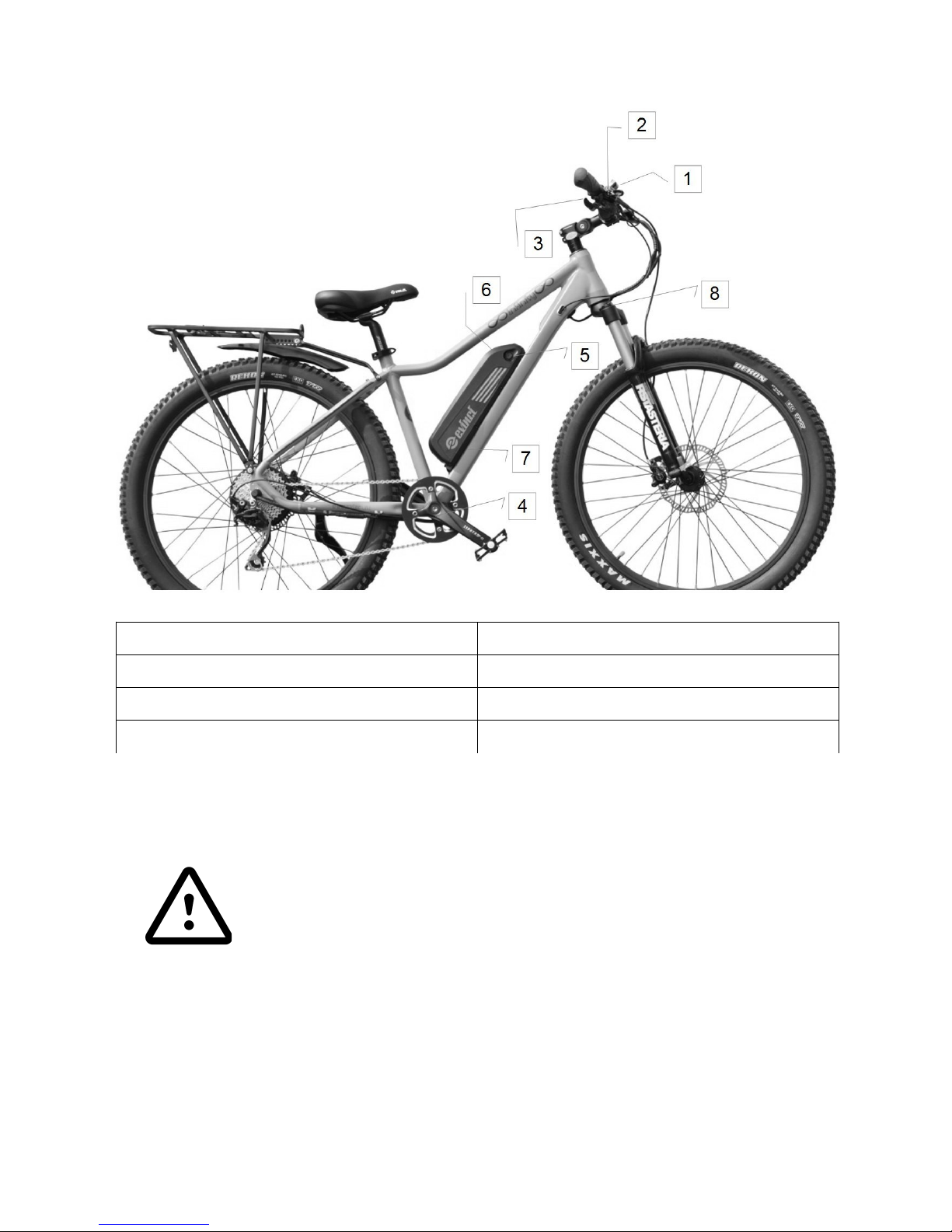
Components
1 LCD Display 5 Battery Charge Port
2 Control Buttons 6 Battery Lock
3 Thumb-Throttle 7 Controller Case
4 Torque Sensor 8 Suspension Damper Control
Basic Safety Tips
Always pull the brakes and hold the handlebar firm and
straight before taking off in order to make sure you keep
control of the bike when power assistance is in action! Also,
keep in mind that the left hand thumb-throttle is active.
5
Page 6
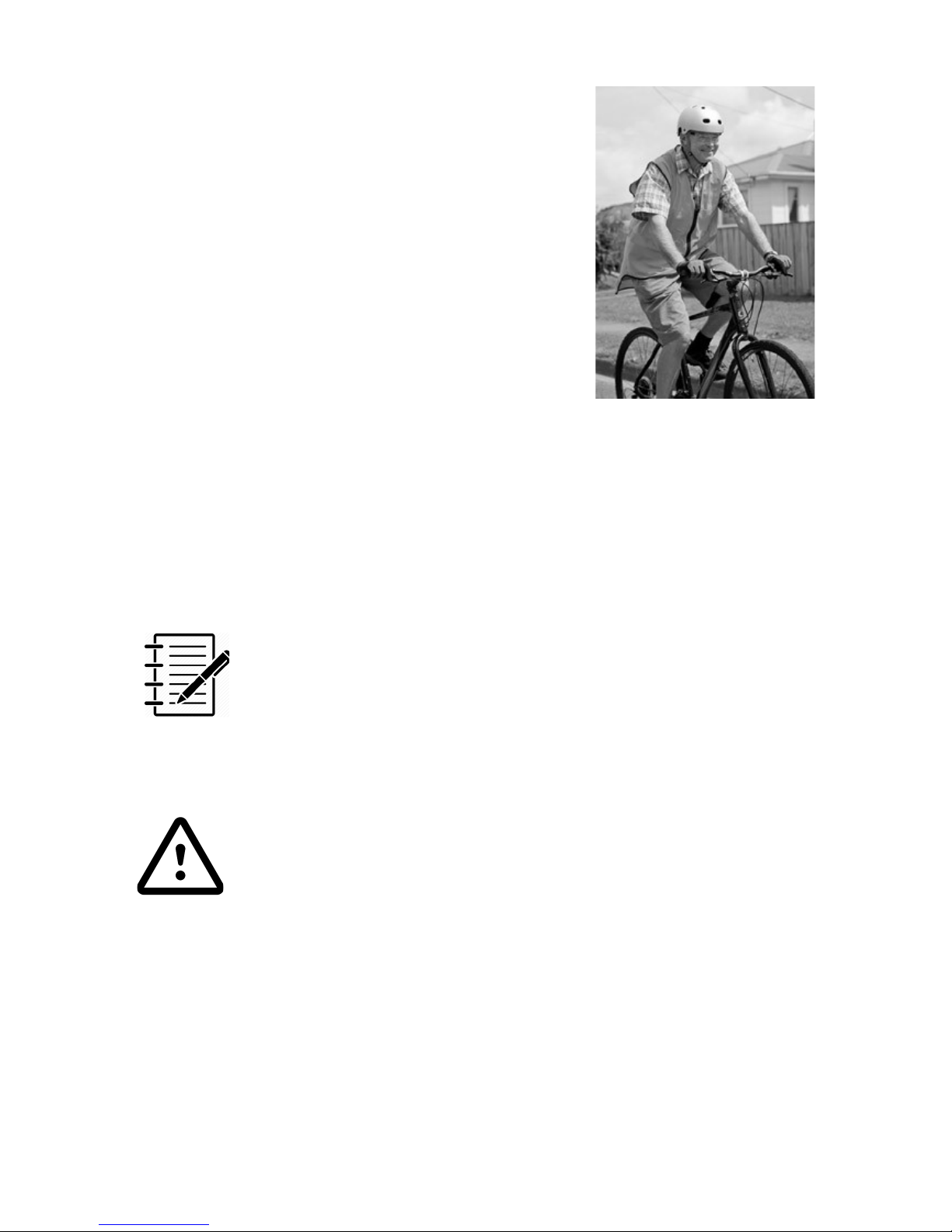
For your own road safety
● Always wear a suitable bike helmet
● Wear bright clothing or reflective elements
to be seen better by other road users
● Wear shoes with a non-slip sole
● Wear close-fitting clothing on your legs or
wear trouser clips
● Wear bicycle gloves
How to use your charger
Your infinity comes with a 3Ah quick charger to charge your battery. Please do
not use any other charger.
The typical time to charge the standard 13Ah battery if it is completely empty is
about 5 hours.
If you want to charge your battery from a car or motor home
(12V systems), NZEBIKES or your retailer can supply a special
charger called PowerBuddy for this purpose.
Before you use the charger the first time please read the following notes
regarding safety carefully!
• Keep the charger away from children!
• In order to prevent any possible injury this charger
should only be used for the original lithium battery
which is supplied together with the infinity e-bike
• Any other battery is not compatible and risks to explode
while charging, causing serious injury to people as well
as damage to other equipment
• Using this charger for batteries not supplied by Volto
could risk catching fire, provoke electric shock and/or
cause serious injury
• Please make sure that the charger is always kept dry
and does not get wet at any time.
6
Ref (1)
Page 7
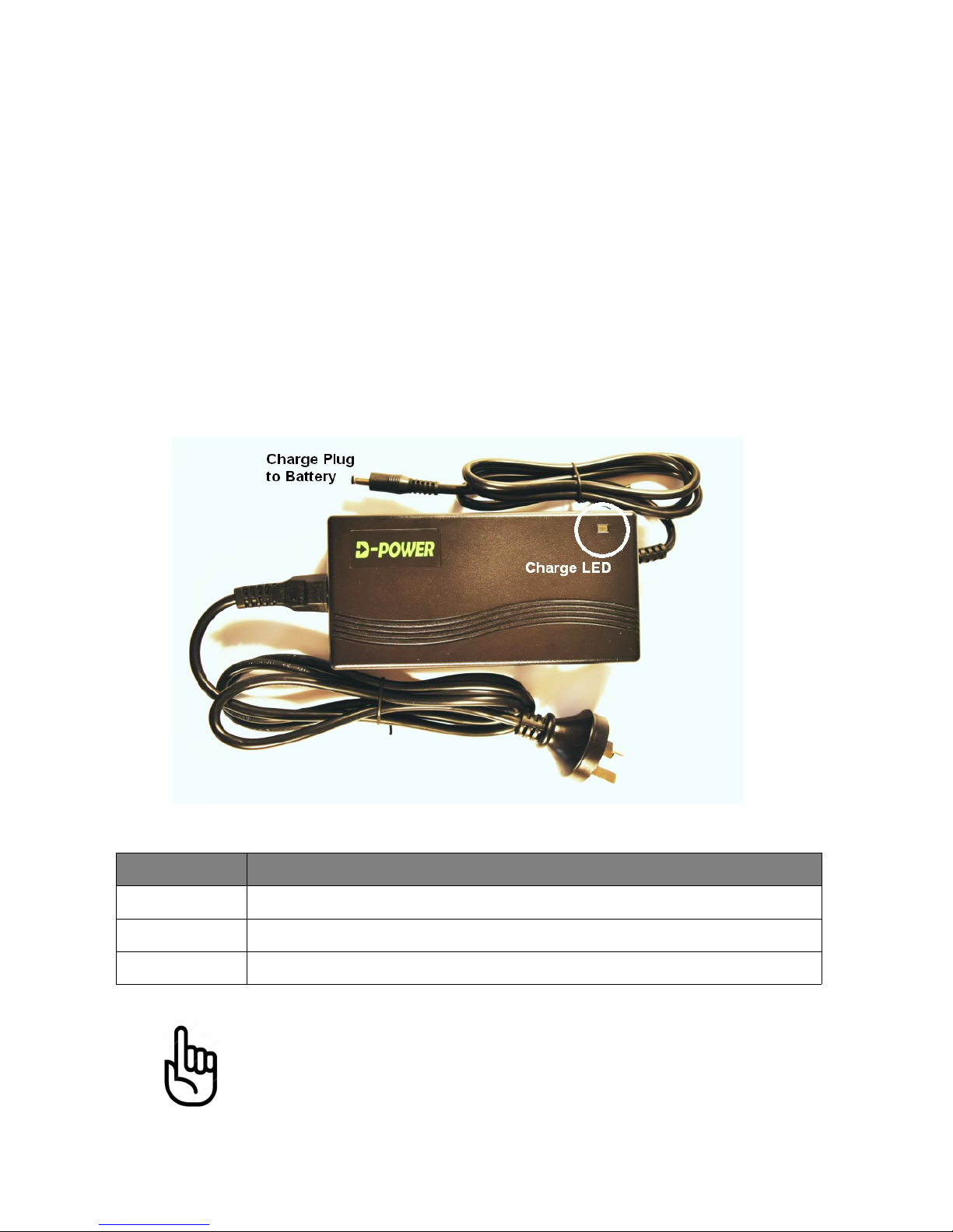
Should there be an incidence of contact with water or any other liquid, make
sure to unplug the charger immediately from the power socket and have it
inspected by your dealer.
Please make sure the charger is always placed on a flat surface when in use.
Also make sure that the charger is always unplugged and removed from the
power socket when not in use.
Before using the charger, always make sure that the plug and the cables are
not damaged.
Never connect a damaged cable or plug to the power socket. Never try to
disassemble the charger. There are no serviceable parts in the charger.
Always unplug the charger before cleaning it. The charger should only be
cleaned with a dry cloth. Never use a wet cloth, oil or any other liquid. Only use
the original cable supplied with the charger.
The charger LED (1) indicates the battery status:
LED STATUS
green the battery is not connected
red the battery is charging
green the battery is charged, the charger has switched off
Before using your battery the first time, it has to be charged
once over night for at least 12 hours.
7
Page 8

Safety notes concerning the battery
• Keep the battery out of reach for children
• Never try to open the battery. Apart from this being
dangerous, all warranty will be void
• Do not provoke a shortcut circuit with metal gadgets
• Remove the battery from the bike when transporting on
an external bike rack
• Do not dip the battery in water or any other liquid
• Do not keep the battery close to heat or open fire
• A battery needs to be re-cycled after use, never throw it
in an open fire as it could explode
• If the battery is damaged because it has been dropped
or because of a biking accident, there might be a risk of
an internal short-circuit. Immediately stop using a
damaged battery.
In order to maximise the use of this battery, please consider the following:
The battery will not charge when exposed to temperatures below +0°C or
above +60°C. It is therefore recommended to keep the battery at room
temperature before charging it.
The charger operates with a microcomputer system with automated control
functions. It automatically stops charging when the battery is full. It cannot be
damaged by overcharging.
None the less, we strongly recommend to always disconnect the power plug
from the wall socket after the battery is charged as power surges, i.e. lightning,
through the grid can damage the charger or battery electronics!
When storing the battery for a longer time period, (e.g. over winter) it is
important to place surface in a dry place. The battery should be re-charged
once every 3 month when it is not used. Negligence could lead to complete
discharge of the battery and this would void the warranty.
The discharging of the battery is due to chemical processes
which are taking place within the battery cells. How much a
battery discharges depends on the time it has not been used
and the temperature it has been exposed to. Thus, a recharge every 3 month, when not in use, is essential.
8
Page 9
Charging the battery
You may charge the battery on the bike or remove it to a
more convenient place.
1. Open the plug cover at the right side of the battery (#5)
2. Connect charger cord to battery
3. Connect the power cord to a mains socket
The charger will get warm while charging – do not cover while
in use as it might cause a malfunction.
How to remove and insert the battery
1. Removal: unlock the battery lock at the left side of the battery
2. Slide battery upwards and then lift it out of the rail
3. Insert: Slide the battery into the battery rail, secure it in the frame with
the battery lock
Before starting to ride
Mount or dismount front wheel
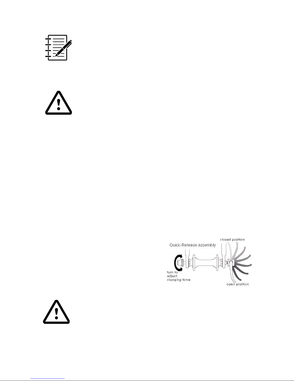
For an easy transport you may remove the front wheel using the quick release
at the front wheel axle.
To remove the wheel open the lever to release the pressure. Now hold the lever
and turn the nut on the other side about 8-9 times – do not remove the nut!
You should be now able to lift the wheel out
of the fork.
To mount the wheel repeat procedure the
other way round. Hold the lever pointing
parallel to the fork in the open position
(downwards), turn the nut till you feel a slight
resistance. Try to close lever – if it goes too
hard undo the nut a bit.
Before every ride make sure the quick release is tightened
properly. To fail so can lead to serious injuries!
9
Page 10
Adjust seat height
Open the quick release lever at the seat clamp, adjust seat height and close the
lever firmly. If the lever is too loose, open the lever again and turn the
adjusting nut clockwise till you feel resistance. Now close lever again. It should
close with noticeable resistance.
Never tighten the seat post if the maximum mark is visible,
otherwise you can injure yourself or damage the seat post.
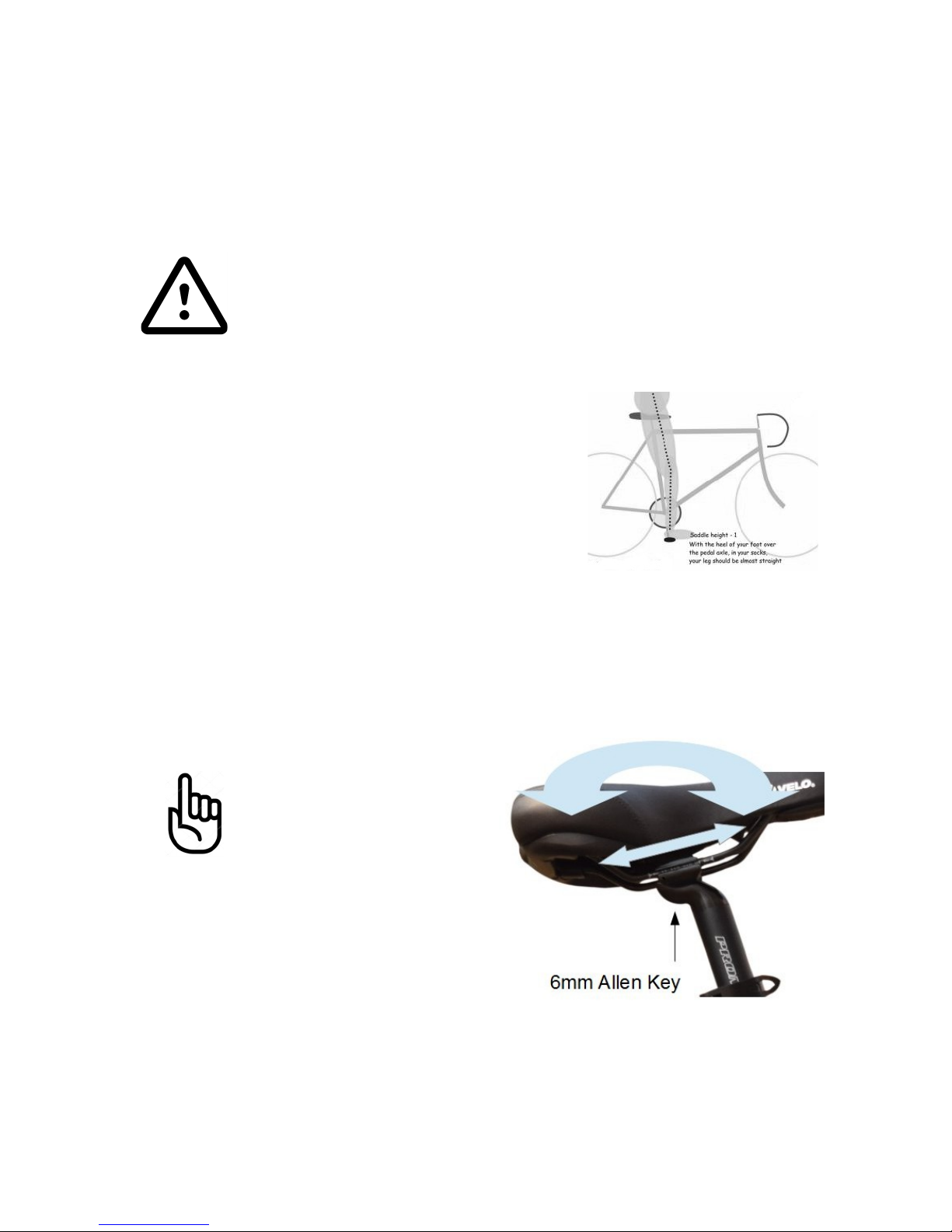
How to find the correct saddle height?
1. Sit on bike saddle
2. Try to reach pedal with your heel when it is in
the bottom position. Your knee should be
more or less fully straightened out
3. Place the ball of your foot on the centre of the
pedal. If your knee is now slightly bend, the
saddle height is correct
Adjusting the saddle angle
Best riding comfort is found when the saddle is horizontal, some riders prefer a
slight forward angled seat.
Never angle a seat
backwards as it can
quickly lead to back pain
or physical injuries
1. Loosen the clamping screw anticlockwise
2. Tilt the saddle to the required angle
3. Tighten the clamping screw
clockwise. Make sure that the screw
is tightened firmly (20 NM)
10
Page 11
Adjust the stem and handlebar
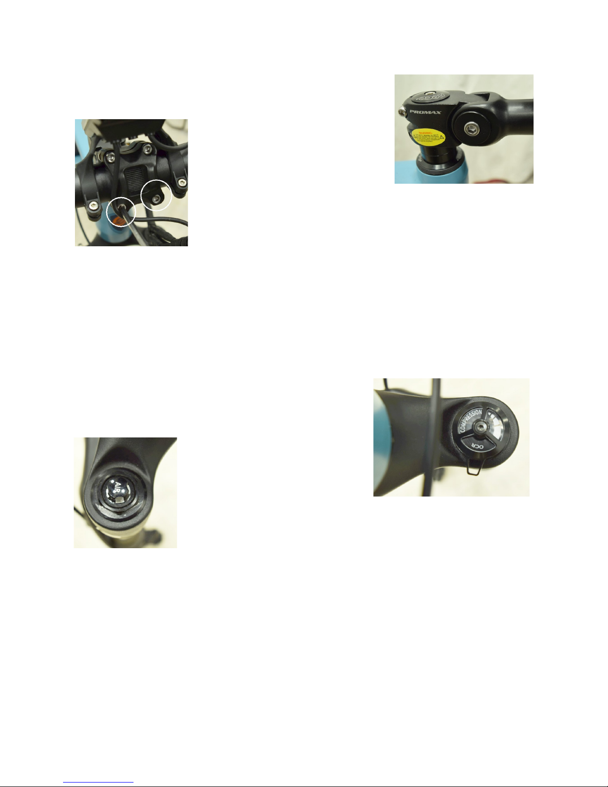
The angle of the stem can be adjusted by opening the
6mm Allen Key screw at the right side of the stem. Do
not remove the screw! There are
two clamp plates, as soon as both
are release you may adjust the
angle. Re-tighten properly!
Adjust the tilt of the handlebar by opening two of the
handlebar clamp screws (upper or lower, 5mm Allen Key).
Check tire pressure
It is very important to maintain the correct tire pressure. Too low pressure will
decrease the range and can lead to rim or tire damages when riding over
kerbs. The recommended tire pressure is 40 psi. For muddy undergrounds the
tire pressure can be reduced to improve traction.
Suspension fork
Your infinity mountain bike is equipped with a high
performance air suspension. This fork allows the
rider to adjust the suspension to their personal
riding style and terrain.
The right side lever allows to
adjust the damping of the oil
cartridge. If the lever is turned
clock wise the damping gets
softer – turned to the left it will get harder.
The pre-load of the air-cartridge can be adjusted on the left
side by adding or releasing air pressure. A special pump is required for this
purpose – your local retailer can help you with this. The pre load should be set
according to the riders weight.
Compression Guideline
When going uphill it is usually better to turn the knob to the maximum left to
prevent fork pumping. For slow and bumpy rides use a softer setting – for fast
rides which need good brake control choose a harder setting to prevent brake
dive.
11
Page 12
Operation
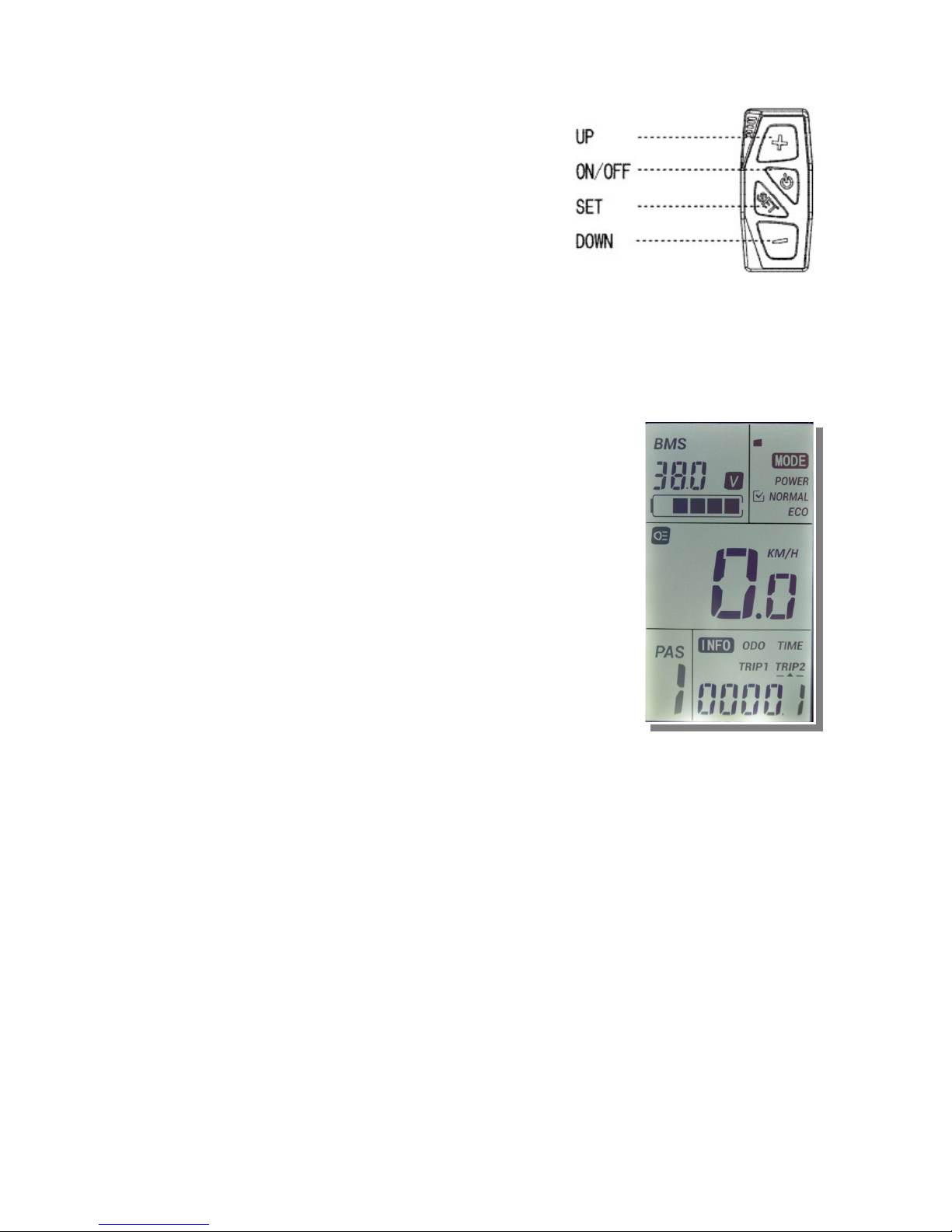
• Turn the display on by pushing the (l)
button
• Select the desired assistance level with
the + or - keys. Start riding.
• Use the throttle as desired to add
additional power to the selected
assistance (the throttle does only add
power according the selected level, this is
a safety measure)
• When finished riding press the (l) button for 3 sec to turn the system off
(it will also turn off after 5 min when not used)
Display
BMS (Battery Management System)
It shows the real voltage of the battery. The range is
between 41.8V for a full battery, down to about ~32V for
an empty battery.
The display also shows the battery level with 5 segments.
Each level is about 20% of power, when the battery
reaches the last 10% the battery frame starts to flash. In
this stage the controller or battery might turn off when a
higher load is applied, i.e. riding up a hill.
MODE: Not used for this setup.
KM/H: shows your current riding speed
PAS: your selected level of assistance. 0 = no support.
INFO: Can be toggled with the SET key. Shows ODO, trip
time and two trip distances.
TRIP1: get accumulated till manual reset or resets when riding more than
500km. To manually reset push the SET key for 2 sec. Push the DOWN key
once. Push SET key for 2 sec.
TRIP2: displays the last driving distance for 30 s after turning on the display,
then resets automatically and start to record the current distance.
TIME: The riding time parameter is automatically reset after shut down.
BACKLIGHT: by pushing the On/Off button the display backlight can be
turned on and off.
Walk assistance: you can activate the motor to support you pushing the bike
up a hill. Press and keep depressed the DOWN button. After 2 seconds the
motor will start with a maximum speed of 6kph.
12
Page 13
Walk assistance is not supposed to be used while riding the
bike
Throttle
The left hand side thumb-throttle allows the rider to add power to the selected
assistance level. This can be useful when starting off or to give you an extra
boost when riding up a hill.
Gears
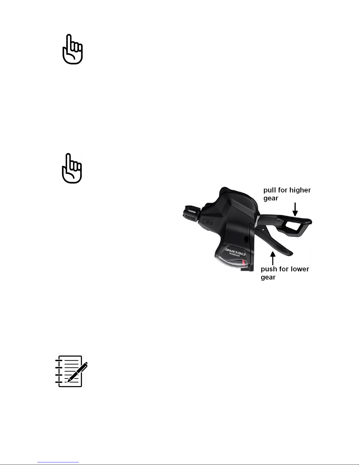
Only change gears while pedalling otherwise the derailleur
might get damaged
If you have to change gears, i.e. to
start off in first gear, lift the rear
wheel using the side stand and turn
the crank while changing the gears.
As a rule of thumb gears on a bike
are changed and used similar to a car
with a manual gearbox.
You will start off in 2st gear, on a flat
road you will choose gear 6 or 7 to
pedal along. Uphill go back to 3 or for
steeper hills gear 1. If you ride faster or downhill choose higher gears.
The assistance level chosen on the display will assist you up to a certain speed.
Choose assistance level and gear according to your needs and riding style.
Watch your crank revelations, if you have the feeling you have to push too hard
at too low revelations, change to a lower gear. If you pedal very fast with less
effort, choose a higher gear or reduce the assistance level.
When you intend to stop it is good practise to change the
gear back to a low gear so you may start off without any
problems. This can easily be done while braking and slowly
pedalling as the motor will not push you further.
13
Page 14
Brakes
We recommend always to use both brakes at the same time – this allows the
rider to take best control over the braking process without stressing the front or
rear brake. To brake efficiently, your front brake is there to stop you and the
back brake is there to shave off speed. Roughly 70-80% of your stopping
power comes from the front brake. Leaving 20-30% for the back brake.
Please note that this bicycles uses high performance hydraulic
brakes with no special motor cut-out. When going around
narrow corners adjust the power support to prevent
unexpected high acceleration.
Maintenance
Your infinity e-bike needs regular maintenance as any other normal push bike.
All bike shops can help you with these maintenance steps.
There is no maintenance necessary on the electrical components.
Brakes
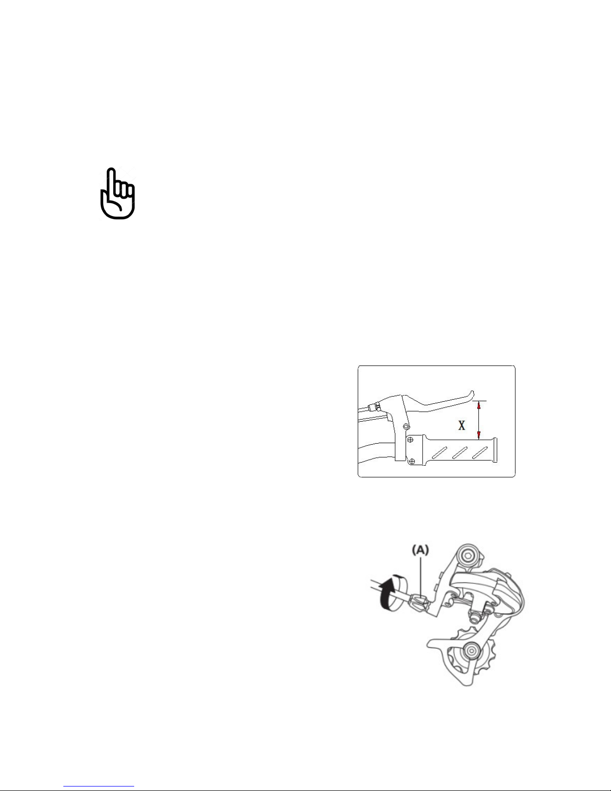
This bikes uses hydraulic brakes which are self
adjusting. If you feel that the brake force gets
lower or the way you have to press the brake
levers exceed 50% of X (Fig 1) most likely the
braking pads have to be replaced. Please see
your local bike shop.
Gears
Our infinity bike uses a solid and easy to maintain
Shimano Deore gear system.
It can happen after a while that gears do not
perfectly change any more or you experience a
rattling noise while pedalling. This is normal due
to the nature of the used control wire hulls which
can get compressed over time. To re-adjust it is
usually enough to slightly tighten the gear wire.
For the rear derailleur turn (A) clockwise while
turning the pedals till the rattle goes away –
otherwise turn counter-clockwise.
14
Fig 1
Page 15

Safety points
We recommend a 6 month interval service or every 1000 km.
Important checkpoints are:
▪ Quick release front axle
▪ headset
▪ stem clamp
▪ bottom bracket and crank
screw
▪ rear wheel axles nuts
▪ seat post clamp
▪ brake caliper screws
▪ spoke tension
Spoke tension has to be checked on a regular interval. Failing
can cause spoke breakage and will void the warranty
Repairing a puncture
With the motor in the rear wheel it is more complex to replace a tire or tube.
In case of a puncture we first recommended to check if the puncture can be
repaired using a patch.
1. Lay bike on the left side side
2. Pull tire of rim
3. Identify puncture in tube and check tire for any sharp objects to be
removed
4. If tube is still repairable apply patch
5. Refit and pump up tire
To remove the rear wheel, first unplug the motor cable at the right side of the
chain stay. When assembling make sure the arrows on the plugs are aligned
and the plug is entirely plugged in. If you get Error 8 on the display, unplug
and try again.
15
Page 16

Trouble shooting
Problem Resolution
Display is turned on, but motor
won't start (throttle or pedalassist)
Display shows error code 8
1. Check motor plug at rear stay. Unplug
once and plug back in (Allign arrows!
Needs some force!)
2. Take bike to your retailer for further
checks.
Battery is charged but display
won't turn on
1. Check plug going from display to frame
harness
2. If possible measure voltage at the
battery socket (left and right pin). If no
voltage can be measured, take battery
to your retailer.
Charger is plugged in, but LED
stays green
Try to use other charger otherwise it might be
a battery fuse fault, please take battery to
your retailer
16
Page 17

Glossary
BMS
BMS is an electronic circuit for battery monitoring. It increases a battery pack's
safety by making sure that all cells are operated within the permitted voltage
range only. When current is too high, temperature is too high or one line of
batteries inside the battery is outside the permitted voltage range the charge
output will be switched off. This avoids total discharge of the battery during
normal operation. An integrated balancer insures that any differences in voltage
between single cells are equalised. In case of a problem with the charging
device the BMS makes sure that the battery cannot be overcharged. A capacity
gauge maybe included to display the remaining capacity.
Controller
The controller is the heart of any electric bicycle. It has the power electronics
to drive the motor and a microprocessor. The controller processes all input
signals coming from the different sensors and it talks to the display on the
handlebar. The microprocessor runs the firmware, which is the piece of
software telling the controller what to do. Firmware updates can be applied to
improve or add functions.
Display
The display is usually mounted to the handlebar and allows the rider to readout
vital information about the e-bike system and control the functions in the
controller. There are different kind of controllers with LED or LCD interface.
Hall sensor
Hall sensors are used in motors, cadence sensors, brake switches and power
throttles. Inside the motor they determine the motor direction and submit it to
the controller so the motor will turn in the right direction right at the start.
Inside the PAS they detect if the magnet disc is rotating. Inside the power
throttle they measure how far the throttle is rotated. Hall sensor can be of the
analogue or digital kind. Functional principal: When hall sensor are passing by a
magnetic field they emit an initial voltage, which is proportional to the product
of magnetic field strength and current (Hall Effect). They are named after their
inventor Edwin Hall.
17
Page 18

Pedal Assist Sensor (PAS)
In an electric bicycle the PAS measures if the crank is moving in riding
direction. This information will be passed on the controller which then activates
the motor to support the rider. The PAS can distinguish between forwards and
backwards movements of the crank.
Torque Sensor
The torque sensor measures the force generated by the rider when pushing
into the pedals. Our sensor measures values between 1 to 80kg and applies
motor support according to the selected PAS level.
References
Ref (1): Ministry of Health NZ, Website
Notes:
18
Page 19

19
Page 20

NZEBIKES 2016 Ltd
19 Esk Street
Tauranga
evinci.nz
Ph: 022 675 2699
evinci™ is a registered trademark of NZEBIKES 2016 Ltd
Rev 1/18
 Loading...