

Page 1
EVIL DETONATOR
OWNER'S MANUAL
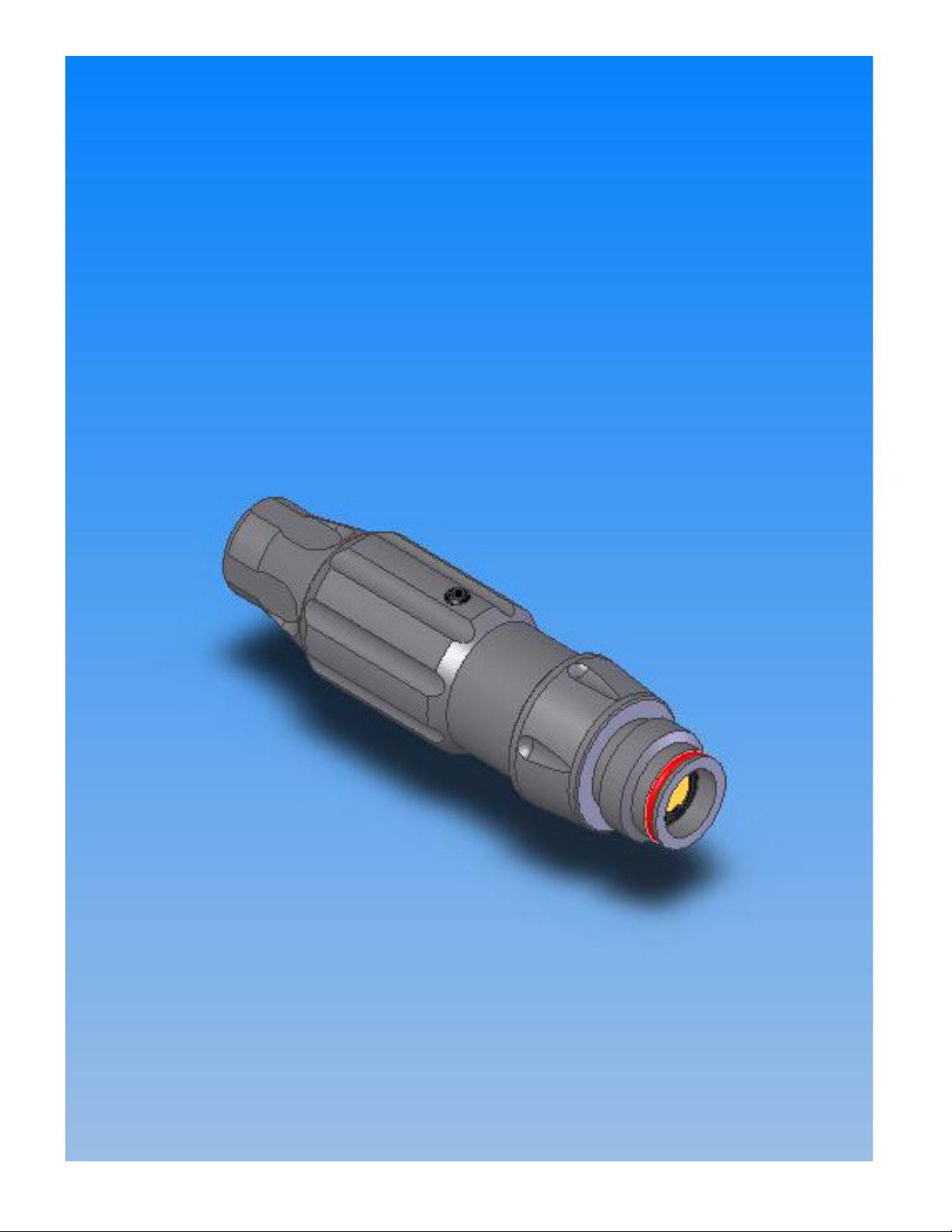
The EVIL DETONATOR represents a new standard for Second Stage regulators.
It's standard .825-14 NGO interface, and 1/8 NPT inlet make it an almost
universal fit on currently available Markers. It's virtually non-existent Response
Curve makes it the only logical choice for today's High Tech, Low Pressure
tournament grade equipment!
Page 2
SPECIFICATIONS
Weight 5.6 ounces
Length (@ max press setting) 4.5 inches
Range of Adjustment (Output) 100 to 550 PSI
Maximum Input Pressure 1200 PSI
Response Curve >0.5%
Inlet Port 1/8 NPT
Outlet Port Std .825-14 NGO
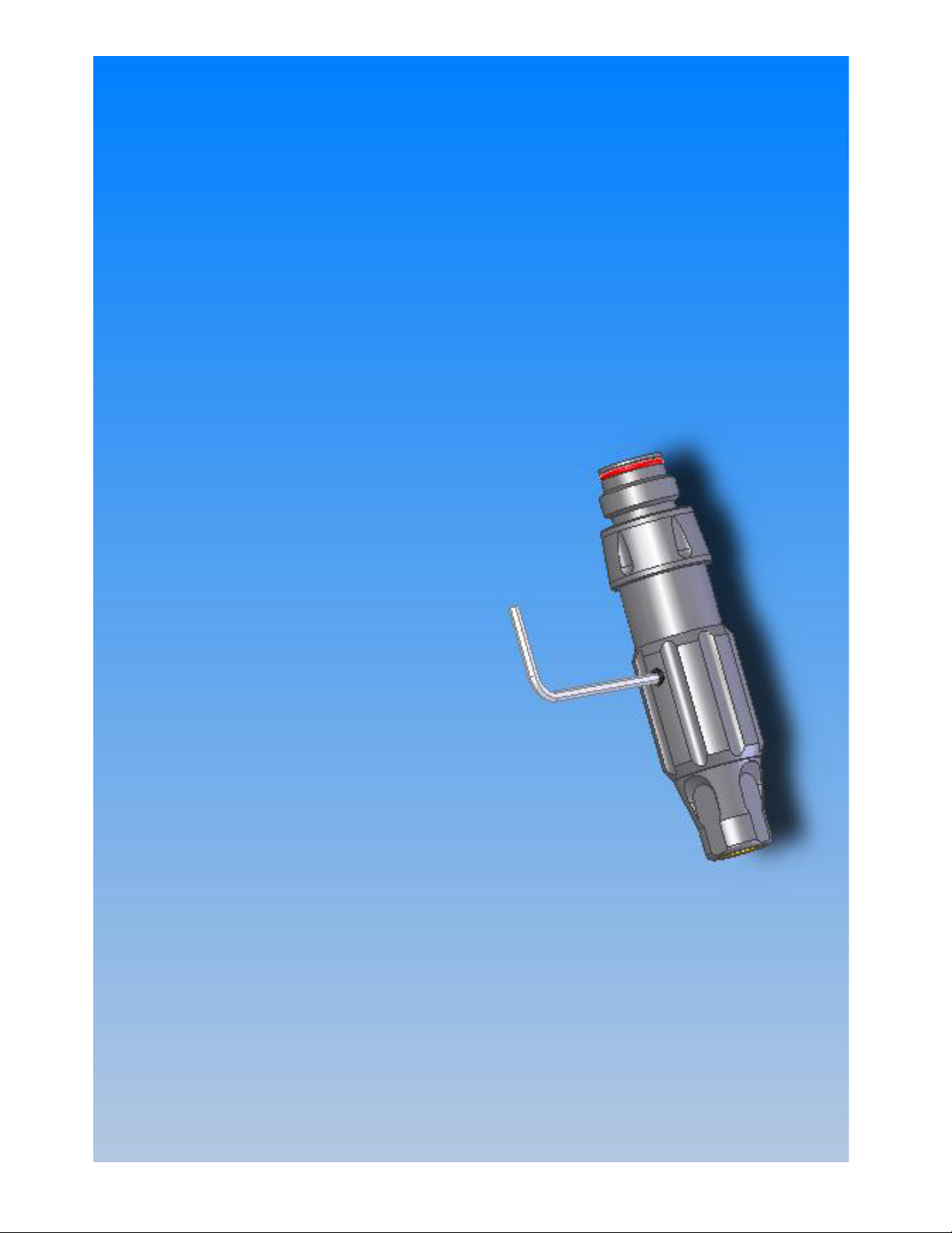
ADJUSTMENT
To adjust Output pressure on the
Detonator, first loosen the locking screw
(using a 3/32” Allen key) in the
Adjusting Collar. It is not necessary to
remove this screw, but it does have to
be turned out at least two turns in order
to clear the detent pocket it engages.
Once this has been done, the adjusting
collar can be rotated to accomplish the
pressure adjustment.
PLEASE NOTE: If you are reducing the
output pressure, remember to either
cycle the marker, or otherwise vent the
downstream pressure as the adjustment
is made. Failure to do so will produce
inaccurate pressure readings, and
possible premature wear on the
regulator sealing element.
Once the adjustment has been made,
re-tighten the locking screw, making
sure that it engages one of the eight
detent pockets provided. Because this
screw engages these positive detents, it
is not necessary to tighten beyond
"Finger Snug".
Page 3

ROUTINE SERVICE
There are only three wear items that will eventually require attention.
The first is the piston Oring, which is a standard 015 series urethane ring. If this
ring wears, you will experience leakage around the adjusting collar. To replace
this ring, remove the snap ring, and gently remove the piston assembly from the
reg body. No other disassembly is required. Be sure to lube the new Oring with
airgun or air tool oil, and to replace the snap ring when re-assembling.
The power tube Oring and the Reg Seat are both reached by the same
procedure, and it will probably save work if they are replaced as a set. A worn
power tube Oring will cause leakage around the adjusting collar, and a worn Reg
Seat will cause inaccurate delivery pressure.
To access these parts, first remove the Adjusting Collar lock screw, and turn the
Adjusting Collar to it's maximum travel. This will expose a second set screw,
which also should be removed (5/64” Allen key). Once that is done, you will be
able to unscrew the Adjusting Collar the rest of the way, and separate the reg
into it's two halves.
When that step is completed, you can grasp the top end of the Seal Retaining
Cap with a pair of SOFT JAW pliers and unscrew it . This will give you access to
both the Oring and the Reg Seat. (See the following page for detail illustration.)
To re-assemble, simply reverse the procedure.
Page 4

Page 5

16
6
5
1
2
?
3
11
10
4
7
17
8
9
14
1 1 INNER TUBE M2003B-600
2 1 REG SEAT M2003B-900
ITEM NO. QTY. PART NO.
3 1 THRUST ELEMENT M2003B-400
4 1 REG SEAL RETAINER M2003B-500
5 1 ADJUSTING COLLAR M2003B-200
6 1 BOTTOM CAP M2003B-300
7 1 MAIN BODY M2003B-100
8 1 POWER TUBE M2003B-800
9 1 PISTON M2003B-245
10 1 SETSCREW 8-32 M2003B-1000
11 1 ORING 008-90U
13 1 ORING 012-90U
14 1 SNAPRING M2003B-1300
15 1 ORING 015-90U
16 1 SETSCREW BALL END 10-32 M2003B-1100
12 1 ORING 011-70B
13 1 ORING 012-90U
14 1 SNAPRING M2003B-1300
15 1 ORING 015-90U
16 1 SETSCREW BALL END 10-32 M2003B-1100
17 1 MAINSPRING M2003B-700
13
15
 Loading...