

Evikon T4511, T3511 Instruction Manual
IE-SNC-Tx5xx-03 1
Intelligent temperature, relative humidity and dew point meter with
ethernet connection
T3511
Intelligent temperature transducer with ethernet connection
T4511
Instruction Manual

IE-SNC-Tx5xx-03 2
Introduction
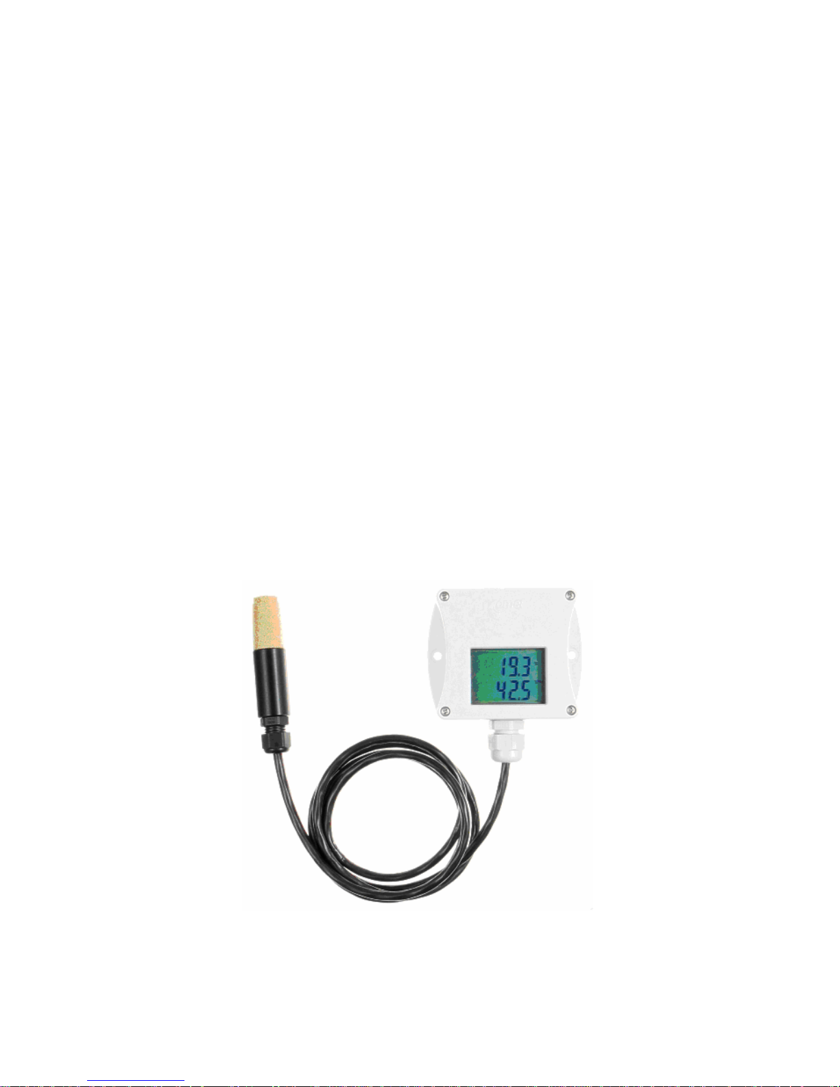
The T3511 meter is designed to measure temperature, relative humidity and a dew point of
air. The communication with the meter is over Ethernet. The meter consists of a plastic case
with electronics and of a plastic probe on a cable with an air filter for temperature and relative
humidity sensors. The probe is connected to the electronics. The device is designed for use in a nonaggressive environment .
The T4511 transducer is designed to measure temperature from an external probe with a
Pt1000/3850ppm sensor. The probe is connected to the transducer by means of terminals. The
transducer is built in a plastic case with the IP65 protection.
Measured values of the transducers
Instrument Model Temperature Humidity Dew point
T3511 X X X
T4511 X - -
Table 1

IE-SNC-Tx5xx-03 3
General safety rules
The following summary is designed to prevent injury hazards or device damage. Operate the
instrument in accordance with this manual to prevent electric trauma.
Service should be performed by a qualified person only.
Precautions against injury or fire
Use a safety ac/dc adapter. Use only an adapter with the power voltage recommended by its
manufacturer and which is approved by proper standards. Check that the adapter has undamaged
cables and cover.
Connect and disconnect correctly. Do not connect and disconnect a LAN cable or lead-in cables if
the device is under electric voltage.
Do not use the instrument without the cover.
Do not use the instrument, if it does not work correctly. If the instrument seems not to work
correctly, have it checked by a qualified service person.
Do not use the instrument in an explosive environment.

IE-SNC-Tx5xx-03 4
Content
Introduction..........................................................................................................................................2
General safety rules..............................................................................................................................3
Content.................................................................................................................................................4
General description..............................................................................................................................5
Preparation to operation.......................................................................................................................5
What is needed to operate instrument..............................................................................................5
Procedure of instrument connection ................................................................................................6
Power voltage.......................................................................................................................................7
Installation............................................................................................................................................7
Installation procedure.......................................................................................................................7
Checking operation..............................................................................................................................8
Calibration............................................................................................................................................8
Storing..................................................................................................................................................9
Description of device functions ...........................................................................................................9
Alarms..............................................................................................................................................9
Modbus ..........................................................................................................................................10
SMTP.............................................................................................................................................11
SNMP.............................................................................................................................................12
WWW ............................................................................................................................................14
Setting of device – Setup ...............................................................................................................17
Global settings ...............................................................................................................................19
E-mail settings- SMTP configuration............................................................................................19
SNMP- Trap Configuration ...........................................................................................................20
WWW- WWW configuration........................................................................................................20
Modbus- Modbus configuration.....................................................................................................20
Alarm configuration.......................................................................................................................21
Factory defaults – setting from the manufacturer..........................................................................21
Save settings...................................................................................................................................21
What to do when…............................................................................................................................21
I forgot the IP address of the device ..............................................................................................21
It is not possible to connect to the device from a LAN..................................................................22
Preventive maintenance .....................................................................................................................23
Technical specification ......................................................................................................................23
Technical parameters:....................................................................................................................23
Common parameters:.................................................................................................................23
Temperature and relative humidity meter T3511 ......................................................................24
Temperature transducer T4511.................................................................................................24
Operating conditions......................................................................................................................24
Access to variables by means of protocols ....................................................................................26
IE-SNC-Tx5xx-03 5
General description
The Tx5xx devices are designed for measurement of temperature, dew point and humidity.
Measured value can be displayed on the instrument LCD display, or it is possible to read it out by
means of an Ethernet interface (to be subsequently processed in a PC). The following formats are
supported:
• www pages with user-design possibility
• modbus protocol
• snmp protocol
The instrument may send a warning message to several defined points if the measured value
gets out of adjusted limits. There are the following possible ways to deliver the warning report:
• to send an e-mail to maximum of three e-mail addresses
• to send a snmp trap to maximum of three IP addresses
• to display an alarm state on the device www page
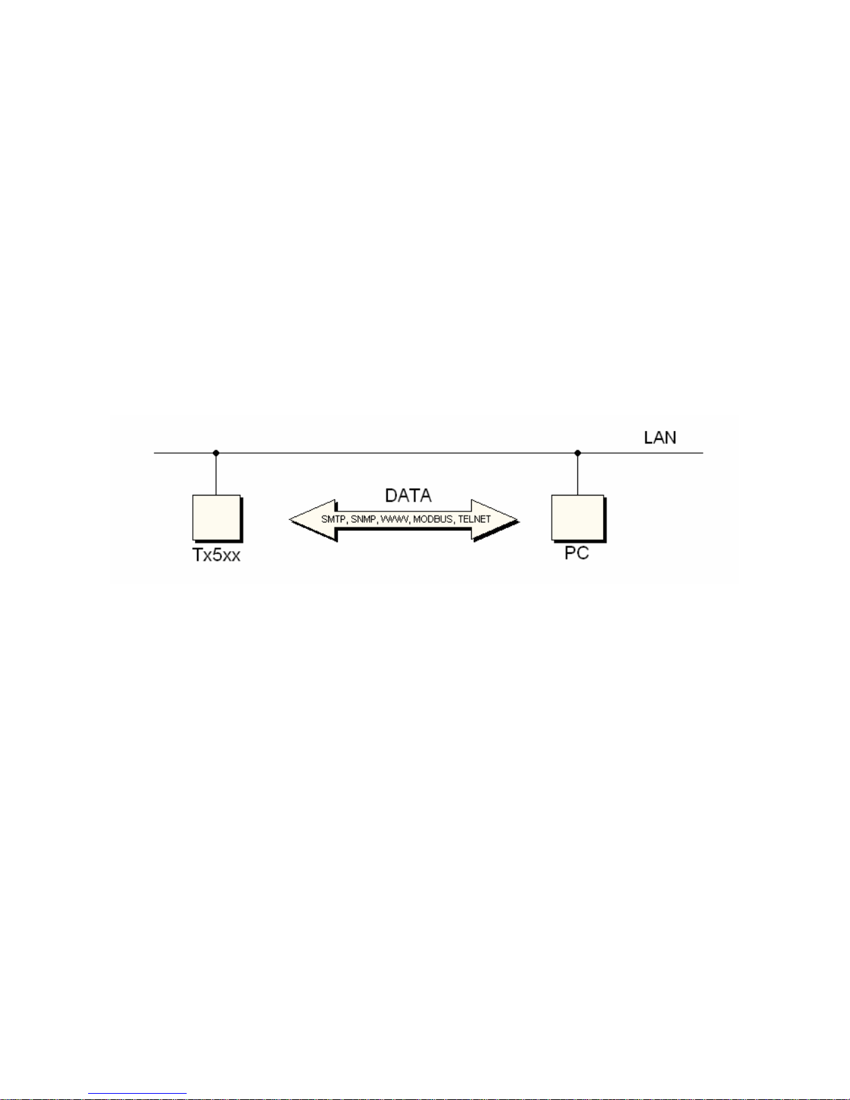
Alarm limits may be set via modbus, telnet or a SNMP MIB table. The alarm state may be
read via the device www pages, the information console or the SNMP MIB table. A block diagram
of the device connection with to the PC is in Figure 1.
Figure 1- block diagram of the connection
Preparation to operation
In order to be able to use all the features of the device it is necessary to do some settings by
means of a PC. In the case of T4511 transducer it is necessary to connect a temperature probe
before use (see chapter Installation, page 7).
What is needed to operate instrument
• ac/dc adapter 9-30V, 200mA (more details - see chapter Power voltage page 7)
• RJ-45 LAN connection
• free IP address in your network
• temperature probe with a Pt1000 sensor for the T4511 transducer
Contact network administrator to get free IP address
Warning! Safety reception of warning messages (e-mail, trap) depends on actual accessability of
required network services. It is recommended to protect device against the unauthorized access to
device settings and connection of cables.
IE-SNC-Tx5xx-03 6
Procedure of instrument connection
T3511 – follow Figure 2
• connect the LAN connector
• connect the power
• configure the device by means of a PC – see chapter Installation, page 7
Figure 2 – procedure of T3511 device connection
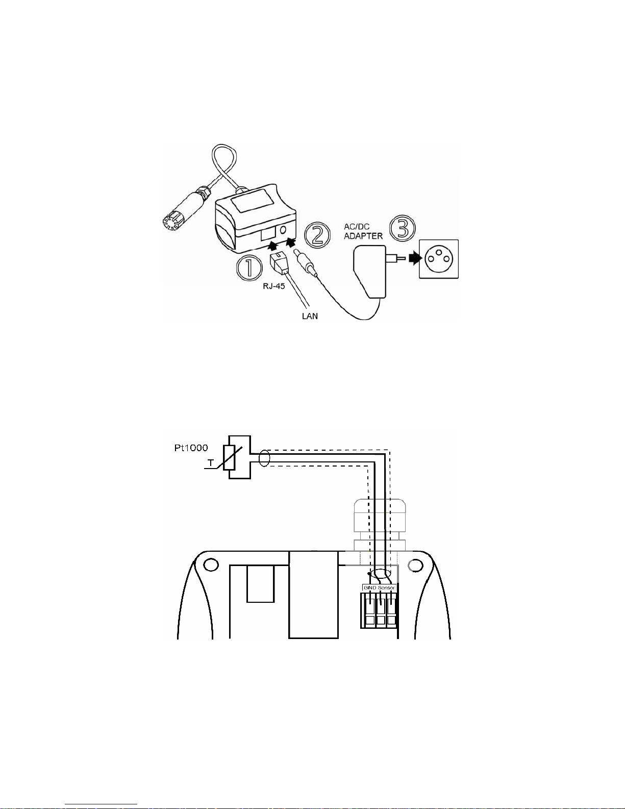
T4511 – proceed in accordance with figures 3 and 4
• unscrew four screws from the front side of the transducer case and remove the lid
• get the cable through a sleeve on the case wall
• connect the LAN connector (Figure 4)
• connect the power supply
• configure the device by means of a PC – see chapter Installation, page 7
Figure 3 – connection of a Pt1000 probe to the T4511 transducer
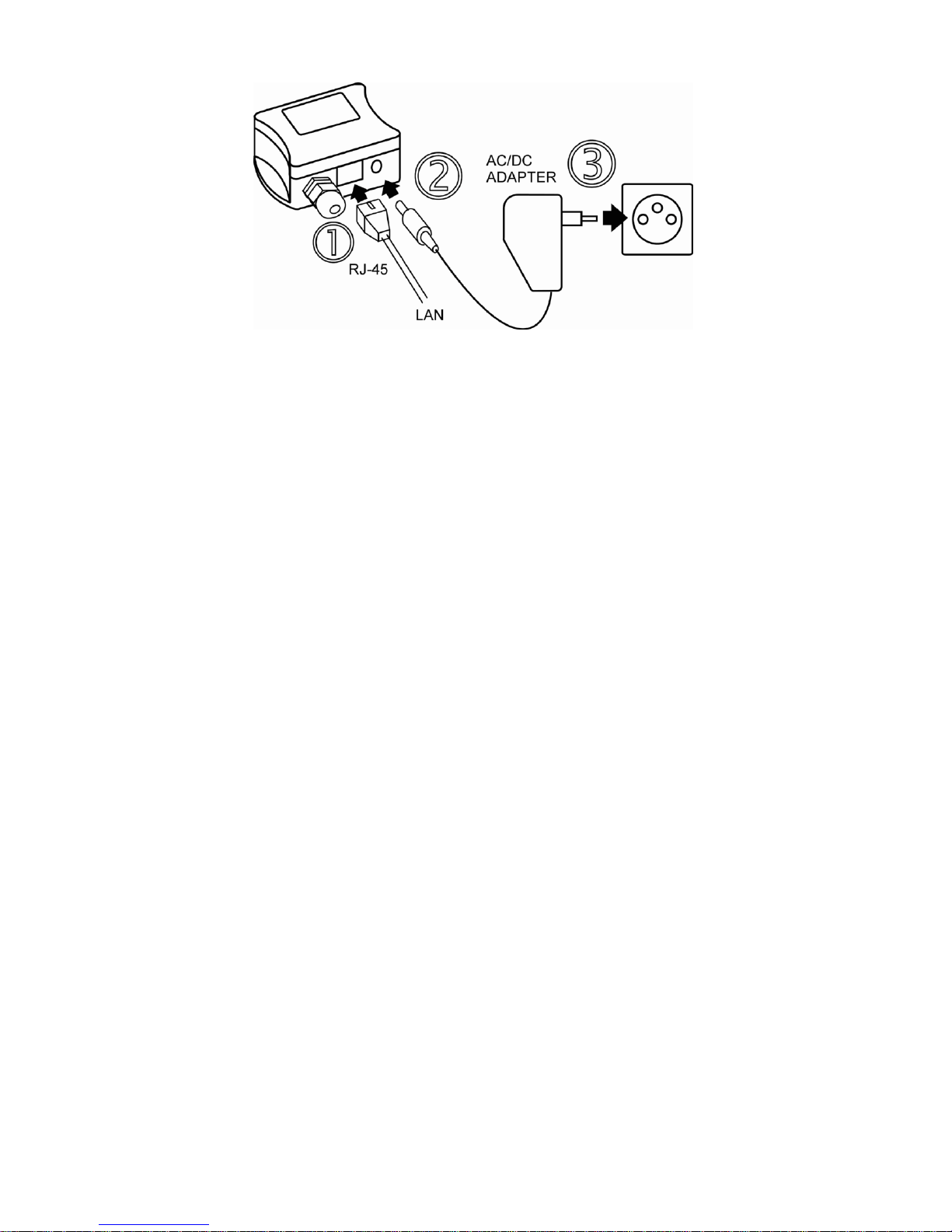
IE-SNC-Tx5xx-03 7
Figure 4. – connection of the T4511 transducer
Power voltage
Power voltage: 9 to 30Vdc, maximum consumption 200mA, connector coaxial, diameter
5 x 2.1 mm, positive pole is the central pole.
Installation
It is necessary to assign a new suitable IP address to the device at the first connection to it in
order to prevent collisions with already existing network IP addresses, and make the address
conform with the local habits. If installing several new devices, connect them to the network one
after another! If a suitable IP address is not known, contact your network administrator and ask him
for the following:
IP address: _____._____._____._____
IP gate address: _____._____._____._____
Mask of network: _____._____._____._____
The IP gate address and the network mask need not be specified if the device will be
operated only in a local network. If you set the IP address to one which is already used in the
network the device will not work correctly and collisions in the network will appear.
The IP address of each device is set by the manufacturer to 192.168.1.213.
Installation procedure
• run a Tx5xx_setup.exe
• set a new IP address of the device (default IP address is 192.168.1.213)
• configure the device in accordance with your requirements (alarm settings, sending of e-
mail, traps…)
• store the settings
See more details about use of the Setup in chapter Setting of device – Setup, page 17.
IE-SNC-Tx5xx-03 8
Checking operation
Visual check
After connecting the power supply the LCD displays a currently measured value (if the LCD
has not been switched off). If the measured value exceeds the measuring range of the temperature
probe or the temperature probe is not connected correctly Err 1 or Err 2 reading appears on the
LCD. In this case check the temperature probe connection and that the value being measured is in
the allowed measuring range. (Connection of the temperature probe is relevant only for the T4511
transducer).
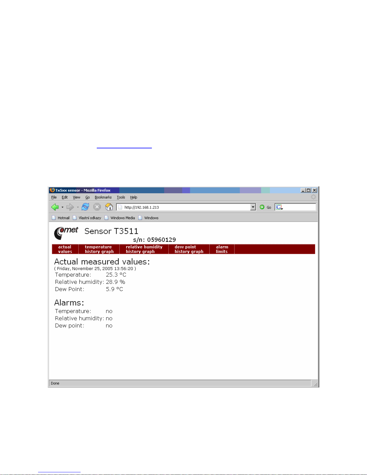
Communication check via a LAN
Open a browser of www pages and enter the device IP address.
Example: http://192.168.1.213
The device displays its name, serial number, measured values, alarm states and alarm
settings (Figure 5). If „Access denied“ appears instead, the display of www pages is not allowed
(Figure 10). (Change the appropriate setting in the Setup - more details in chapter WWW- WWW
configuration, page 20).
Figure 5 – device www pages
Calibration
Recommended calibration interval is
• one year for T3511
 Loading...