

IE-SNC-Tx5xx-03 1
Intelligent temperature, relative humidity and dew point meter with
ethernet connection
T3511
Intelligent temperature transducer with ethernet connection
T4511
Instruction Manual
IE-SNC-Tx5xx-03 2
Introduction
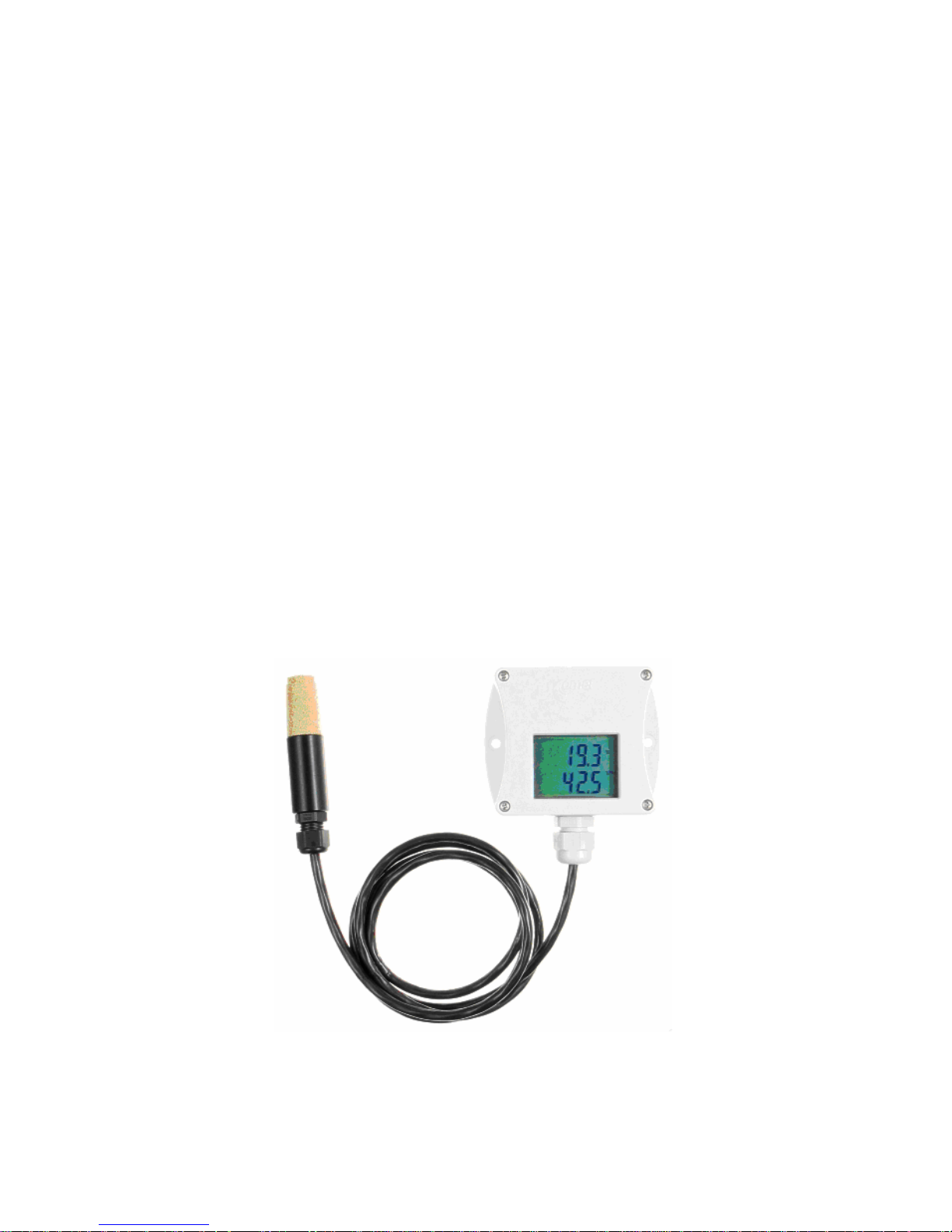
The T3511 meter is designed to measure temperature, relative humidity and a dew point of
air. The communication with the meter is over Ethernet. The meter consists of a plastic case
with electronics and of a plastic probe on a cable with an air filter for temperature and relative
humidity sensors. The probe is connected to the electronics. The device is designed for use in a nonaggressive environment .
The T4511 transducer is designed to measure temperature from an external probe with a
Pt1000/3850ppm sensor. The probe is connected to the transducer by means of terminals. The
transducer is built in a plastic case with the IP65 protection.
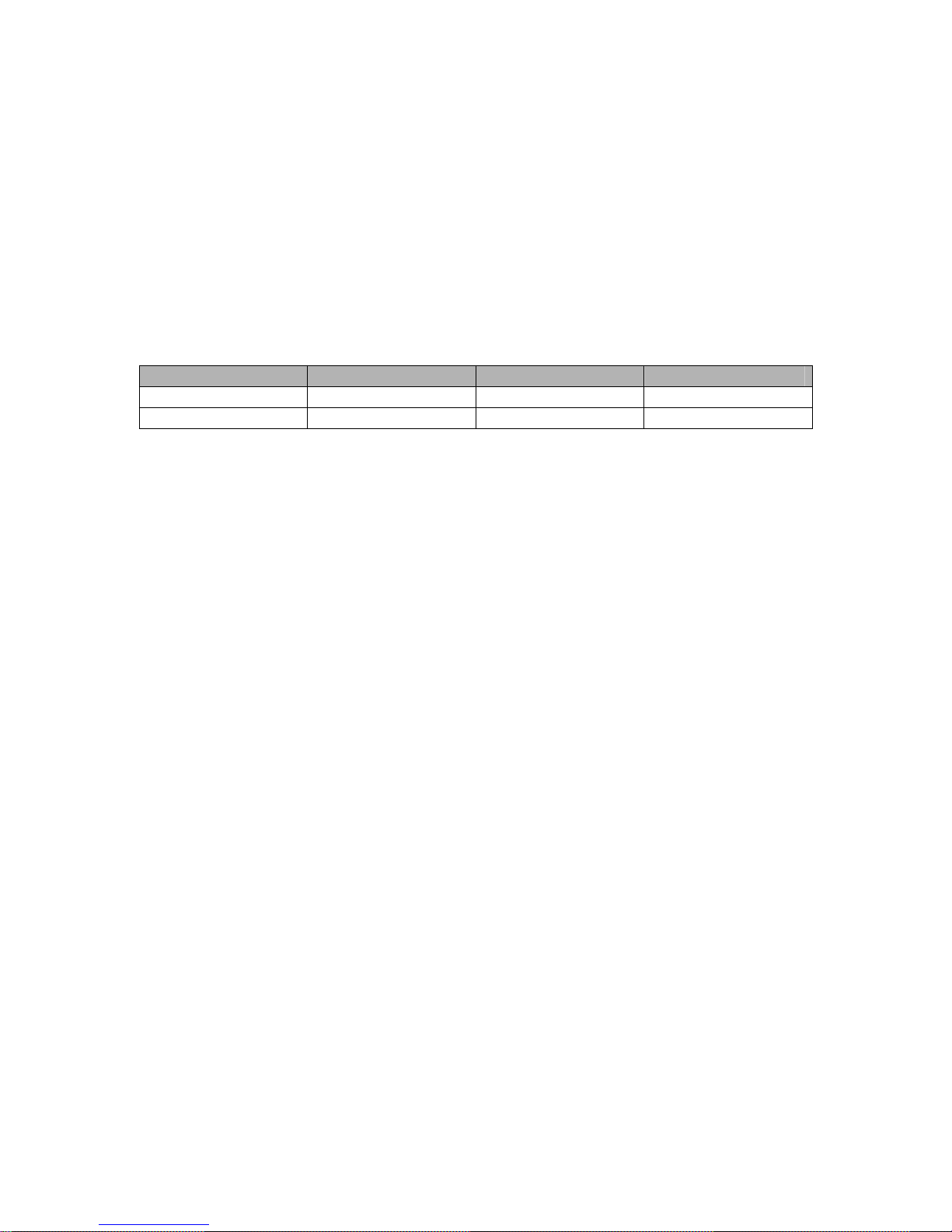
Measured values of the transducers
Instrument Model Temperature Humidity Dew point
T3511 X X X
T4511 X - -
Table 1

IE-SNC-Tx5xx-03 3
General safety rules
The following summary is designed to prevent injury hazards or device damage. Operate the
instrument in accordance with this manual to prevent electric trauma.
Service should be performed by a qualified person only.
Precautions against injury or fire
Use a safety ac/dc adapter. Use only an adapter with the power voltage recommended by its
manufacturer and which is approved by proper standards. Check that the adapter has undamaged
cables and cover.
Connect and disconnect correctly. Do not connect and disconnect a LAN cable or lead-in cables if
the device is under electric voltage.
Do not use the instrument without the cover.
Do not use the instrument, if it does not work correctly. If the instrument seems not to work
correctly, have it checked by a qualified service person.
Do not use the instrument in an explosive environment.

IE-SNC-Tx5xx-03 4
Content
Introduction..........................................................................................................................................2
General safety rules..............................................................................................................................3
Content.................................................................................................................................................4
General description..............................................................................................................................5
Preparation to operation.......................................................................................................................5
What is needed to operate instrument..............................................................................................5
Procedure of instrument connection ................................................................................................6
Power voltage.......................................................................................................................................7
Installation............................................................................................................................................7
Installation procedure.......................................................................................................................7
Checking operation..............................................................................................................................8
Calibration............................................................................................................................................8
Storing..................................................................................................................................................9
Description of device functions ...........................................................................................................9
Alarms..............................................................................................................................................9
Modbus ..........................................................................................................................................10
SMTP.............................................................................................................................................11
SNMP.............................................................................................................................................12
WWW ............................................................................................................................................14
Setting of device – Setup ...............................................................................................................17
Global settings ...............................................................................................................................19
E-mail settings- SMTP configuration............................................................................................19
SNMP- Trap Configuration ...........................................................................................................20
WWW- WWW configuration........................................................................................................20
Modbus- Modbus configuration.....................................................................................................20
Alarm configuration.......................................................................................................................21
Factory defaults – setting from the manufacturer..........................................................................21
Save settings...................................................................................................................................21
What to do when…............................................................................................................................21
I forgot the IP address of the device ..............................................................................................21
It is not possible to connect to the device from a LAN..................................................................22
Preventive maintenance .....................................................................................................................23
Technical specification ......................................................................................................................23
Technical parameters:....................................................................................................................23
Common parameters:.................................................................................................................23
Temperature and relative humidity meter T3511 ......................................................................24
Temperature transducer T4511.................................................................................................24
Operating conditions......................................................................................................................24
Access to variables by means of protocols ....................................................................................26
IE-SNC-Tx5xx-03 5
General description
The Tx5xx devices are designed for measurement of temperature, dew point and humidity.
Measured value can be displayed on the instrument LCD display, or it is possible to read it out by
means of an Ethernet interface (to be subsequently processed in a PC). The following formats are
supported:
• www pages with user-design possibility
• modbus protocol
• snmp protocol
The instrument may send a warning message to several defined points if the measured value
gets out of adjusted limits. There are the following possible ways to deliver the warning report:
• to send an e-mail to maximum of three e-mail addresses
• to send a snmp trap to maximum of three IP addresses
• to display an alarm state on the device www page
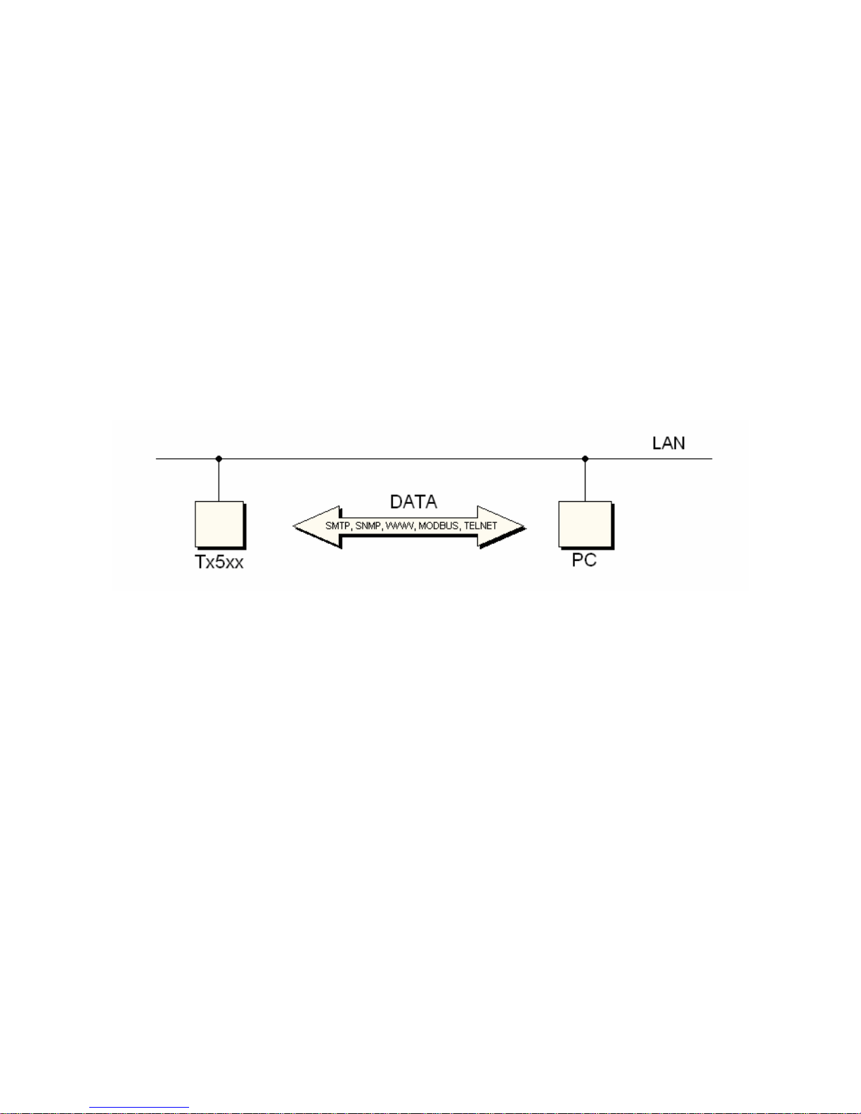
Alarm limits may be set via modbus, telnet or a SNMP MIB table. The alarm state may be
read via the device www pages, the information console or the SNMP MIB table. A block diagram
of the device connection with to the PC is in Figure 1.
Figure 1- block diagram of the connection
Preparation to operation
In order to be able to use all the features of the device it is necessary to do some settings by
means of a PC. In the case of T4511 transducer it is necessary to connect a temperature probe
before use (see chapter Installation, page 7).
What is needed to operate instrument
• ac/dc adapter 9-30V, 200mA (more details - see chapter Power voltage page 7)
• RJ-45 LAN connection
• free IP address in your network
• temperature probe with a Pt1000 sensor for the T4511 transducer
Contact network administrator to get free IP address
Warning! Safety reception of warning messages (e-mail, trap) depends on actual accessability of
required network services. It is recommended to protect device against the unauthorized access to
device settings and connection of cables.
IE-SNC-Tx5xx-03 6
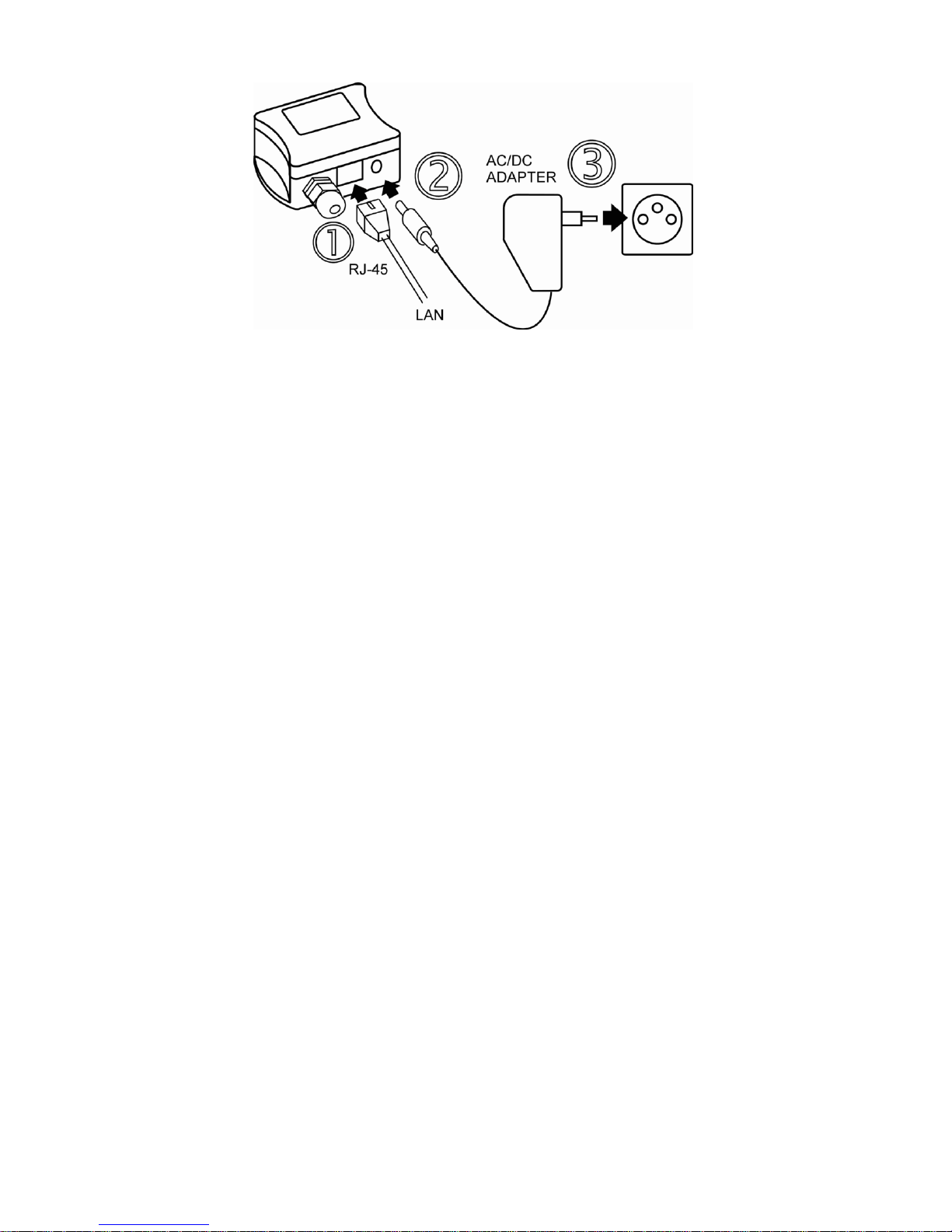
Procedure of instrument connection
T3511 – follow Figure 2
• connect the LAN connector
• connect the power
• configure the device by means of a PC – see chapter Installation, page 7
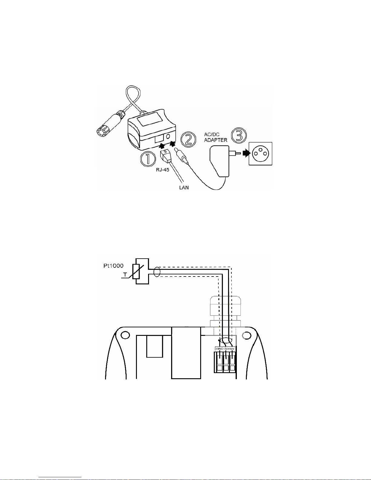
Figure 2 – procedure of T3511 device connection
T4511 – proceed in accordance with figures 3 and 4
• unscrew four screws from the front side of the transducer case and remove the lid
• get the cable through a sleeve on the case wall
• connect the LAN connector (Figure 4)
• connect the power supply
• configure the device by means of a PC – see chapter Installation, page 7
Figure 3 – connection of a Pt1000 probe to the T4511 transducer
IE-SNC-Tx5xx-03 7
Figure 4. – connection of the T4511 transducer
Power voltage
Power voltage: 9 to 30Vdc, maximum consumption 200mA, connector coaxial, diameter
5 x 2.1 mm, positive pole is the central pole.
Installation
It is necessary to assign a new suitable IP address to the device at the first connection to it in
order to prevent collisions with already existing network IP addresses, and make the address
conform with the local habits. If installing several new devices, connect them to the network one
after another! If a suitable IP address is not known, contact your network administrator and ask him
for the following:
IP address: _____._____._____._____
IP gate address: _____._____._____._____
Mask of network: _____._____._____._____
The IP gate address and the network mask need not be specified if the device will be
operated only in a local network. If you set the IP address to one which is already used in the
network the device will not work correctly and collisions in the network will appear.
The IP address of each device is set by the manufacturer to 192.168.1.213.
Installation procedure
• run a Tx5xx_setup.exe
• set a new IP address of the device (default IP address is 192.168.1.213)
• configure the device in accordance with your requirements (alarm settings, sending of e-
mail, traps…)
• store the settings
See more details about use of the Setup in chapter Setting of device – Setup, page 17.
IE-SNC-Tx5xx-03 8
Checking operation
Visual check
After connecting the power supply the LCD displays a currently measured value (if the LCD
has not been switched off). If the measured value exceeds the measuring range of the temperature
probe or the temperature probe is not connected correctly Err 1 or Err 2 reading appears on the
LCD. In this case check the temperature probe connection and that the value being measured is in
the allowed measuring range. (Connection of the temperature probe is relevant only for the T4511
transducer).
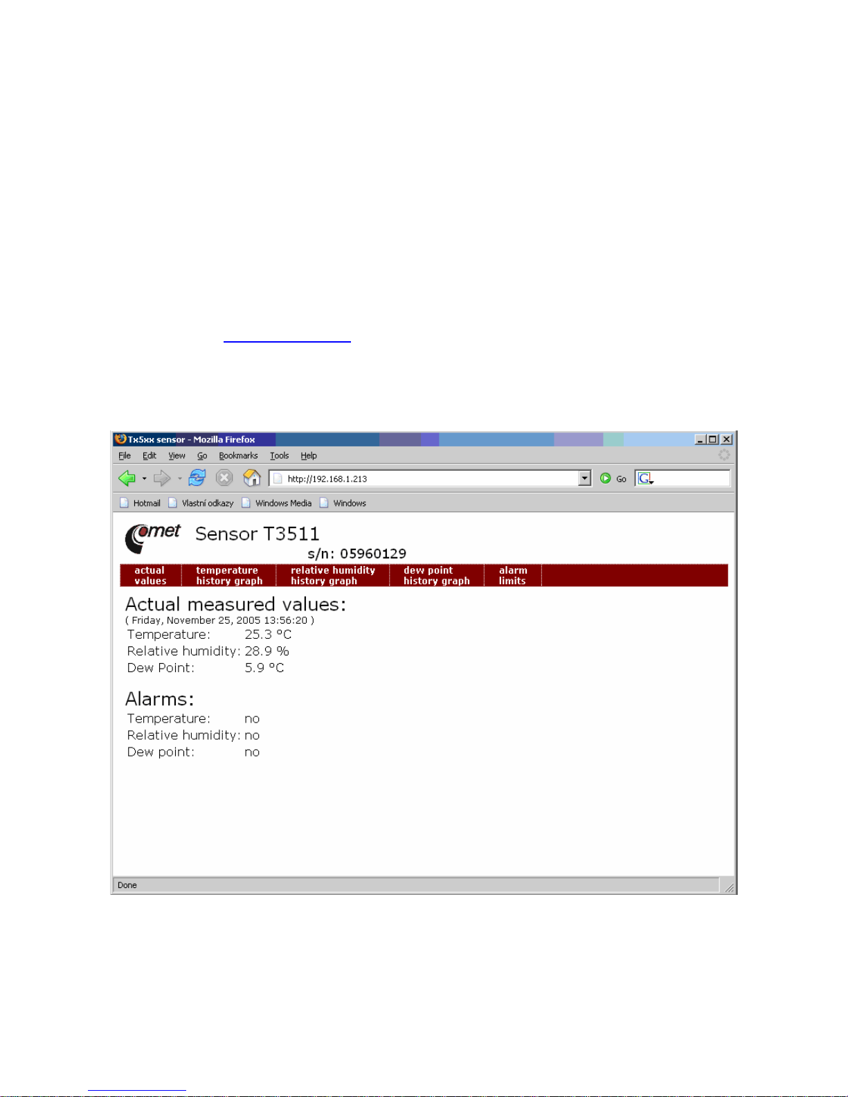
Communication check via a LAN
Open a browser of www pages and enter the device IP address.
Example: http://192.168.1.213
The device displays its name, serial number, measured values, alarm states and alarm
settings (Figure 5). If „Access denied“ appears instead, the display of www pages is not allowed
(Figure 10). (Change the appropriate setting in the Setup - more details in chapter WWW- WWW
configuration, page 20).
Figure 5 – device www pages
Calibration
Recommended calibration interval is
• one year for T3511

IE-SNC-Tx5xx-03 9
• two years for T4511
Storing
Store the device in a temperature range of -30 to +80 °C, non condensing humidity 0 to 99 %RH.
Description of device functions
Information provided by the device can be read on its LCD display or by means of the
following protocols. To communicate via SNMP and modbus protocols it is necessary to have
appropriate software installed on the computer. Such software is not included in the delivery.
The following part describes functions and features of the device.
Alarms
It is possible to set an upper limit, lower limit, hysteresis and time delay to each measured
value.
Description of alarm function
Figure 6 shows a temperature curve with some specified upper limit (temp_limit_high) and
hysteresis. At point 1 temperature exceeds the limit. From that moment a time delay is counted
(time_delay) after which an alarm is set. Because at point 2 the temperature dropped below the
limit value (temp_limit_limit) before the time delay expired, alarm was not set.
Figure 6 – temperature curve
At point 3 the temperature again exceeded the limit, and because it did not drop below the
limit value (temp_limit_high) before the time delay ended, the alarm was set at point 4. At this
moment the alarm e-mails and traps are sent, if they are enabled, and the alarm flag is set (the flag is
set when the alarm is active and reset when inactive). The state of the flag can be found on the
www pages or via Modbus or the information console. The alarm lasted to point 5, where the
temperature dropped below the limit value given by the adjusted hysteresis (temp_limit_high–
hysteresis).
For other measured values the principle of alarm activity is analogical.
An alarm report is always sent right after an alarm appears. The device memorizes sent
alarm reports of current alarms while the power is connected. In case of power disconnection or a

IE-SNC-Tx5xx-03 10
reset of the device (e.g. by modification of configuration) a new alarm evaluation is performed and
new alarm reports are sent again, if any.
It is possible to set the alarm parameters via telnet, modbus protocol or a SNMP MIB table.
Detailed description of setting via these protocols can be found in chapters informing about
particular services.
Modbus
The device contains support for the Modbus protocol to communicate with control systems.
The protocol runs in the RTU mode. The port is set to 501 (for more details about the Setup see
chapter Setting of device – Setup, page 17). The modbus address of the device is always set to 1.
Port 501 enables full access, i.e. both read and write operations are supported. Access to
port can be disabled in the Setup.
Supported Modbus commands:
Command Code Description
Read multiple register(s) 0x03 Reads 16 bit register(s)
Write multiple register(s) 0x10 Writes 16 bit register(s)
Modbus registers of the device:
Variable Unit Format Address Size[bits] Status
measured temperature
[°C]
Int*10 0x0031
16
r
measured relative humidity
[%]
Int*10 0x0032
16
r
dew point temperature (DP)
[°C]
Int*10 0x0033
16
r
lower limit for temperature
[°C]
Int*10 0x5001
16
r/w
upper limit for temperature
[°C] Int*10
0x5002
16
r/w
lower limit for humidity
[%] Int*10
0x5003
16
r/w
upper limit for humidity
[%] Int*10
0x5004
16
r/w
lower limit for dp
[°C] Int*10
0x5005
16
r/w
upper limit for dp
[°C] Int*10
0x5006
16
r/w
temperature hysteresis
[°C] Int*10
0x5007
16
r/w
tolerated time of exceeding of
temperature
[s] uInt 0x5008 16 r/w
RH hysteresis
[%] Int*10
0x5009
16
r/w
tolerated time of exceeding of RH
[s] uInt
0x500A
16
r/w
DP hysteresis
[%] Int*10
0x500B
16
r/w
tolerated time of exceeding of DP
[s] uInt
0x500C
16
r/w
Temperature alarm status
[-] Ascii
0x500D
16
r
RH alarm status
[-] Ascii
0x500E
16
r
DP alarm status
[-] Ascii
0x500F
16
r
Legend:
• r register is designed for read
• w register is designed for write
• Int*10 register is in format of integer*10.
• uInt register is at range of 0-65535

IE-SNC-Tx5xx-03 11
• Ascii character
Temperature, RH and DP alarm states can have the following values:
• no value is inside of adjusted limits
• lo value is lower than adjusted limit
• hi value is higher than adjusted limit
Registers can be read one by one. But it is necessary to write all 15 values to the memory
0x5001 – 0x500F together as a block (alarm states are not affected).
SMTP
In case of exceeding adjusted limits of measured values the device can send e-mails to
maximum of three addresses. Maximum length of an e-mail address is 55 characters. It is necessary
to set your SMTP server address for correct function of e-mail sending. Procedure how to set SMTP
is described in chapter Setting.
If limits of several measured values are exceeded a special alarm e-mail is sent for each
alarm state.
Dummy address sensor@[device IP address] is displayed as a sender of the email. It is not possible to reply to this address. In the Subject field of the message the sentence
Alarm [Description of the device]* is displayed or Test message
[Description of the device] in the case of sending a test e-mail.
*[Description of the device] can be entered in the Setup (chapter Global settings, page 19)
The description of the device is preset to the string TRh-Sensor, or T-Sensor depending
on the device model. Figure 7 shows a message reporting exceeding the temperature limit.

IE-SNC-Tx5xx-03 12
Figure 7 – example of an e-mail from the device reporting exceeding of temperature limit
Format of the message:
• Information report
• Temperature overflow – temperature limit exceeded
• Humidity overflow – humidity limit exceeded
• Dew point overflow – dew point temperature limit exceeded
• Currently measured value at the time when the alarm was raised
• Current setting of alarm limits.
• For actual info please visit http://[IP device]. Have a nice day – for actual
information please visit www pages of the device at address http://[IP address
device].
SNMP
By means of the SNMP protocol it is possible to find currently measured values, read and
set parameters concerning alarms. In case of alarm activation, warning message (a trap) can be sent
to specified addresses. By means of the SNMP MIB table it is also possible to display history of last
100 measured values.
For read and write the device communicates via port 161. Traps are sent via port 162.
Sending of traps can be disabled in the Setup.
The following traps sent:
0/0 reset of the device
1/0 testing trap
6/3 report on a measured value being outside of the limits or a return of the measured value to
the limits

IE-SNC-Tx5xx-03 13
For the correct function of the SNMP server it is necessary to store the MIB table RFC-
1213.mib and Tx5xx.mib to the client MIB. The path to the device is then:
iso.org.dod.internet.private.enterprises.comet.products.tx5xx.
MIB tables are available at www pages http://www.cometsystem.cz or on the installation CD in the
MIB directory.
There are the following other branches of the tree:
Branch List Description Write Format Complete path
Readings temperature current
temperature
no string 1.3.6.1.4.1.22626.1.2.1.1.0
humidity current humidity no string 1.3.6.1.4.1.22626.1.2.1.2.0
dewpoint current dew
point
no string 1.3.6.1.4.1.22626.1.2.1.3.0
Settings templow lower limit of
temperature
no string 1.3.6.1.4.1.22626.1.2.2.1.0
temphigh upper limit of
temperature
no string 1.3.6.1.4.1.22626.1.2.2.2.0
humiditylow lower limit of
humidity
no string 1.3.6.1.4.1.22626.1.2.2.3.0
humidityhigh upper limit of
humidity
no string 1.3.6.1.4.1.22626.1.2.2.4.0
dewpointlow lower limit of
dew point
no string 1.3.6.1.4.1.22626.1.2.2.5.0
dewpointhigh upper limit of
dew point
no string 1.3.6.1.4.1.22626.1.2.2.6.0
temptime time delay for
temperature
alarm alerting
no Int 1.3.6.1.4.1.22626.1.2.2.7.0
humidityTime time delay for
humidity alarm
alerting
no Int 1.3.6.1.4.1.22626.1.2.2.8.0
dewPointTime time delay for
dew point alarm
alerting
no Int 1.3.6.1.4.1.22626.1.2.2.9.0
tempHyst temperature
hysteresis
no string 1.3.6.1.4.1.22626.1.2.2.10.0
humidityHyst humidity
hysteresis
no string 1.3.6.1.4.1.22626.1.2.2.11.0
dewPointHyst dew point
hysteresis
no string 1.3.6.1.4.1.22626.1.2.2.12.0
readingsint temperaturei current
temperature
no int*10 1.3.6.1.4.1.22626.1.2.3.1.0
humidity current humidity no int*10 1.3.6.1.4.1.22626.1.2.3.2.0
dewpointi current dew
point
no int*10 1.3.6.1.4.1.22626.1.2.3.3.0
settingsint templowi lower limit of
temperature
yes int*10 1.3.6.1.4.1.22626.1.2.4.1.0

IE-SNC-Tx5xx-03 14
temphighi upper limit of
temperature
yes int*10 1.3.6.1.4.1.22626.1.2.4.2.0
humiditylowi lower limit of
humidity
yes int*10 1.3.6.1.4.1.22626.1.2.4.3.0
humidityhighi upper limit of
humidity
yes int*10 1.3.6.1.4.1.22626.1.2.4.4.0
dewpointlowi lower limit of
dew point
yes int*10 1.3.6.1.4.1.22626.1.2.4.5.0
dewpointhighi upper limit of
dew point
yes int*10 1.3.6.1.4.1.22626.1.2.4.6.0
temptimei time delay for
temperature
alarm alerting
yes Int 1.3.6.1.4.1.22626.1.2.4.7.0
humidityTimei time delay for
humidity alarm
alerting
yes Int 1.3.6.1.4.1.22626.1.2.4.8.0
dewPointTimei time delay for
dew point alarm
alerting
yes Int 1.3.6.1.4.1.22626.1.2.4.9.0
tempHysti temperature
hysteresis
yes int*10 1.3.6.1.4.1.22626.1.2.4.10.0
humidityHysti humidity
hysteresis
yes int*10 1.3.6.1.4.1.22626.1.2.4.11.0
dewPointHysti dew point
hysteresis
yes int*10 1.3.6.1.4.1.22626.1.2.4.12.0
history temperature temperature no int*10 1.3.6.1.4.1.22626.1.2.6.1.1.1
humidity humidity no int*10 1.3.6.1.4.1.22626.1.2.6.1.1.2
dewPoint dew point no int*10 1.3.6.1.4.1.22626.1.2.6.1.1.3
Meaning of trap list strings values:
• 0 trap was not sent – measured value is within the limits
• 1 upper limit exceeded
• 2 lower limit exceeded
Password for a read operation is set by the manufacturer to PUBLIC, password for write is
set to PRIVATE. These passwords may be changed in the setup.
History
By means of the MIB table it is possible to display history of the last 100 measured values,
stored in adjusted time interval. This interval is set in the Setup (chapter SNMP- Trap
Configuration, page 20). If a value has not been measured yet or an error was detected the value is
9999. The history is erased after each restart of the device.
WWW
The device supports display of measured values, adjusted limits and alarm states on its www
pages. The address of the www pages is identical with its IP address. There are the two modes
supported:
• text version
• user-defined web (Graphics web)

IE-SNC-Tx5xx-03 15
In the user-defined web is possible show the history graphs, including pictures and upload
self-made web to device. More info about user-defined web you can find on http://cometsystem.cz
section programs. You can switch between this modes in setup. The demo of user-defined web is
showed on picture 8-b.
The web address is the same like the device IP.
Example: The device has an IP address 192.168.1.204. Enter http://192.168.1.204 to the browser
address field and confirm it with the Enter key. If your setup enables display of www pages
and the user-defined web is disabled, page will be displayed as in Figure 8-a.
Figure 8-b – User-defined web

IE-SNC-Tx5xx-03 16
Figure 8-a – www pages of the device
Description of the device is displayed on line 1. Description is displayed also in the subject
of the e-mail, if sending is enabled. Currently measured values follow: temperature, humidity, dew
point, alarm states and setting of alarms. In case of the T4511 temperature transducer, only
temperature readings are displayed.
WWW pages have adjustable automatic refresh interval. The manufacturer sets it to 60
seconds. The value can be modified in the setup in a range of 10–65535s. If the device has www
pages display disabled screen as in Figure 9 appears.

IE-SNC-Tx5xx-03 17
Figure 9 –device with disabled www pages display
Setting of device – Setup
The Setup is designed for managing device settings. Setting is performed by means of
Tx5xx_setup program, or telnet. Setting thru the telnet is described in separated document on
http://www.cometsystem.cz. Access to the Setup can be protected by a password. The Tx5xx_setup
program you can find on http://www.cometsystem.cz or on istallation cd.
Setting of the device:
• run the Tx5xx_setup.exe program
• enter the device IP address to “Enter device IP” field and press “Connect”. The factory
default IP address is 192.168.1.213. If you don’t know the device’s IP address, press the
“Find device…” button to enter to find window. In this window select wanted device field
and press the “Select” button
Figure 11 – Connect sensor

IE-SNC-Tx5xx-03 18
Figure 12 - Find device
• next to press the “Connect” button will be the device settings showed (Fig. 13). By the
T4511 device will be the humidity and dew point settings not appears.
Figure 13 – Sensor settings

IE-SNC-Tx5xx-03 19
Global settings
Contact your network administrator to get the correct values of the IP address, mask,
gateway. Entering incorrect values can cause the device be not found in the network or other
complications!
Sensor IP: setting of the IP address of the device.
Gate IP: setting of the internet gateway. The value need not be entered if the device will operate
only in a local network.
Netmask: setting of the network mask of your network.
Example:
mask no. of bits
255.255.255.252 2
255.255.255.0 8
255.128.0.0 23
Configuration password: change of the access password for telnet.
Sensor name: The description of the device (it is possible to change it if needed). This description
is displayed on WWW pages and in subjects of sent e-mails. Its maximum length is 32 characters.
E-mail settings- SMTP configuration
Sending warning e-mail: Enabling of sending warning e-mails after alarm activation.
SMTP IP: setting of an IP address of the SMTP server. Correct setting is required for the device to
be able to send e-mails . Contact your network administrator to get the correct address.
recipient 1-3: e-mail addresses of warning e-mail recipients.
Send test email: In case of confirmation a test e-mail is sent to the specified addresses.

IE-SNC-Tx5xx-03 20
Figure 14 – Example of the Test E-mail
SNMP- Trap Configuration
traps sending enable: enabling/disabling of sending SNMP traps.
Password for read: setting of the password for access to SNMP MIB tables.
Password for write: setting of the password for write to SNMP MIB table of the device.
Trap IP 1-3: the IP address of recipients of SNMP traps.
Send test trap: Sends a test trap of type 1/0 to the specified IP addresses.
WWW- WWW configuration
WWW enable: enables the display of www pages
Web refresh time: interval for automatic page refresh (update of measured values). Range 10–
65535 s.
Graphics web enabled: switch between user-defined web and web text mode.
Modbus- Modbus configuration
Setting of Modbus. The device provides access to measured values by means of the modbus
The port is non-adjustably fixed to 501
Modbus Channel 1 enabled : enables the access to the device

IE-SNC-Tx5xx-03 21
Alarm configuration
Setting of alarms. This submenu contains:
• setting of upper temperature limit
• setting of lower temperature limit
• setting of temperature hysteresis
• setting of temperature time delay
• setting of upper limit for humidity
• setting of lower limit for humidity
• setting of hysteresis for humidity
• setting of time delay for humidity
• setting of upper limit for dew point
• setting of lower limit for dew point
• setting of hysteresis for dew point
• setting of time delay for dew point
Factory defaults – setting from the manufacturer
This selection sets the Setup items to the following values:
• sets SMTP server address to 0.0.0.0
• erases addresses of e-mail recipients
• disables sending of e-mails
• erases addresses of snmp traps recipients
• disables sending of traps
• enables display of www pages
• set Graphics web
• sets refresh time of www pages to 60 seconds
• enables access via modbus
• sets history logging interval to 60 s
• setting of alarms: upper temperature limit: 300 °C, lower temperature limit: -200 °C,
temperature hysteresis: 1 °C, time delay for alarm activation after exceeding temperature
limit: 30 s, upper humidity limit: 100 %RH, lower humidity limit: 0 %RH, humidity
hysteresis: 1 %RH, time delay for humidity alarm activation after exceeding limit: 30 s,
upper limit of dew point: 80 °C, lower limit of dew point: -50 °C, hysteresis of dew point:
1 °C, time delay for dew point alarm activation after exceeding limit: 30 s.
• set sensor name to TRh-Sensor or T-Sensor
Save settings
Saves modifications to the memory and resets the device.
What to do when…
I forgot the IP address of the device
Finding the device IP address
IP address is set to the value 192.168.1.213 by the manufacturer. If you changed it and
forgot the new IP address, run the Tx5xx_setup program and press the “Find…” button. In a new
window all sensors will be show.

IE-SNC-Tx5xx-03 22
It is not possible to connect to the device from a LAN
In the “Find device” window is only IP and MAC address displayed
The next informations are displayed as N/A. This problem will be occurred, when the device IP is
set to another LAN.
In Tx5xx_Setup.exe program choose Tools/Change device IP.
Figure 15- Change device IP address
Press the “Find device” button, in new created window select your unconectable sensor. IP and
MAC address will be displayed in Change Device IP address window. Enter the new sensor IP
address to New device IP address field. Be ensure, that the new IP address is unused, and press the
“Set IP” button.
The sensor IP address in Find device window is not displayed
In program Tx5xx_Setup. exe Select Tools/Change device IP. In change Device IP address (Fig.
15) select “Manual MAC enter”, to “Device MAC address” field enter the device MAC address in
format xx-xx-xx-xx-xx-xx ( e.g. 00-20-4A-84-F0-80) and press the “Set IP” button.
Finding the MAC address
The MAC address is a unique address of a device which is necessary to be known e.g. in
case when there are several devices connected to the network. Procedure:
• disconnect the device power supply
• unscrew four screws holding the lid
• remove the lid
• there is a number in the format 00-20-xx-xx-xx-xx on the network connector label below the
bar code. This is the MAC address of the device which is necessary to be known if the
device IP address is not known.
It is not possible to find meter after manual MAC enter
In program Tx5xx_Setup.exe menu select Tools/Change device IP. In this window ( Fig. 15)
select “Manual MAC enter” and “Set IP to ARP only”. To “Device MAC address” enter the meter
MAC address (e.g. 00-20-4A-84-F0-80) and press the “Set IP” button.
Open telnet to the IP address you assigned to the device MAC address by running a telnet
command telnet [IP_address_assigned_to_MAC_address] 9999 and confirm with
the Enter key.
Example: telnet 192.168.1.254 9999 and Enter. After the welcome message
******** TRh-Sensor Setup 1-3-3.02 ********
MAC address 00204A872FB5
Software version V╚Äěő (050907) CPK_580_XPTEX

IE-SNC-Tx5xx-03 23
Press Enter for Setup Mode
press Enter. Choose 0- Global Settings, set the meters IP address, clear the gate IP, no. of net mask
set to 0. Pres the Enter key, until you are not back into a menu. Press 9 Save and Exit. The
connection will be closed. Now you can connect to meter by the Tx5xx_setup program.
Display is off:
• check if the power is connected
• disconnect and connect the power - watch the display at the moment of connecting the
power. If all LCD segments light for 1 second and go out again, the disply is turned off by
the software.
There is an Err 1 or Err 2 reading on the LCD:
• check if a temperature probe is connected or if the temperature probe is not at a temperature
outside the measuring range (only T4511 temperature transducer)
• check the integrity of the probe cable (only T4511 temperature transducer)
Forgotten password to the setup:
• disconnect the power
• unscrew upper lid of the device case
• press the button inside the device and connect the power at the same time. Keep the button
pressed
• keep the button pressed for 10 s - then the password will be erased
• close the device
Preventive maintenance
Pay heed to recommended calibration interval. Do not subject the device to mechanical
stress.
Technical specification
Technical parameters:
Common parameters:
Power voltage: 9 to 30 V DC, maximum consumption 200 mA
Measuring interval: 0,5 s
Display refresh: 0,5 s
Communication with computer: Ethernet connection (RJ-45 connector)
Protection: IP30 - case with electronics
EMC: device complies EN 61326-1:
Devices are conformed EN 50081-1 and EN 50082-1 in the range:
Radiation: EN 55022 class B
Immunity: EN 61000-4-2 levels 4/8 kV, class A
EN 61000-4-3 intensity of electromagnetic field 3 V/m, class A
EN 61000-4-4 levels 1/0.5 kV, class A
EN 61000-4-6 intensity of electromagnetic field 3 V/m, class A

IE-SNC-Tx5xx-03 24
Temperature and relative humidity meter T3511
Device protection: IP42
Temperature measuring range: -30 to +105 °C
Resolution of temperature: 0.1 °C
Accuracy of temperature measurement:
• ± 0,4 °C from -30 to +80 °C
• ± 0,5 °C over +80 °C
Time response to temperature step: t90 < 6 min, probe with sintered bronze filter, at temperature
step 20 °C
Relative humidity measuring range: 0 to 100 %RH, temperature compensated
Relative humidity resolution: 0.1 %RH
Accuracy of relative humidity measurement: ± 2,5 %RH from 5 to 95 %RH at 23 °C
Time response to relative humidity step: t90< 60 s, probe with bronze filter, at humidity step
60%, air flow approximately 0.5 m/s at constant temperature
Temperature and humidity measuring range is limited accordingly with graph below !(Figure
16)
Dew point: value is calculated from temperature and humidity
Range of dew point measurement: -60 to +105 °C
Dew point resolution: 0.1 °C
Accuracy of dew point measurement: ± 0,5 °C from 30 to 95 %RH
Temperature transducer T4511
Probe: Pt1000/3850 ppm, connected by shielded cable of 10m maximum length
Temperature measuring range: -200 to +600 °C
Temperature resolution: 0.1 °C
Accuracy of temperature measurement:
• ±0.2 °C from -100 to +100 °C
• ±0.2 % from reading outside of the above range
Operating conditions
Operating temperature range:
T3511: instrument -30 to +80 °C, probe -30 to +105 °C
T4511: instrument -30 to +80 °C, external probe - depends on probe model.
LCD display must be switched off at temperature over 70°C!
Operating temperature and humidity range:
electronics T3511, T4511: -30 to +80 °C, 0 to 99 % RH (not condensing)
probe T3511: -30 to +105 °C, 0 to 100 %RH
LCD display must be switched off at temperature over 70°C!

IE-SNC-Tx5xx-03 25
Figure 16 – operating range T3511
Outer characteristics in accordance with EN 33-2000-3:
Normal environment with the specifications: AE1, AN1, AR1, BE1
Working position: arbitrary
Installation of the instrument: by means of two holes at the bottom part
Not allowed manipulations:
It is not allowed to operate the device under conditions other than specified in technical
parameters. Devices are not designed for locations with chemically aggressive environment.
Temperature and humidity sensors must not be exposed to direct contact with water or other
liquids. It is not allowed to remove the sensor cover—to avoid any mechanical damage of
the sensors.
Limits on conditions (the device without a probe): temperature -40 to +80 °C, humidity 0 to 99
%RH
Mechanical dimensions of the case (W x H x D): 88 x 98 x 36 mm
Mechanical dimensions of the external probe: ∅18 mm, length approximately 90 mm, standard
cable length 1 m
Weight: approximately 240 g
Material of the case: ABS
Liquidation: Device itself (after its life) is necessary to liquidate ecologically!

IE-SNC-Tx5xx-03 26
Access to variables by means of protocols
Variable
Modbus
telnet
www
snmp
configuration SW
variable
modbus
telnet
www
snmp
configuration SW
global setting:
measurement:
password for telnet X X temperature I I I
IP address X X relative humidity I I I
description of the device X I X dew point temperature I I I
logging interval for history X I X
history (t,rh,dp) I I temperature lower limit I X I X X
sending of emails/traps X X temperature upper limit I X I X X
humidity lower limit I X I X X
smtp:
humidity upper limit I
X I X X
smtp server-email ip X X dew point lower limit I X I X X
e-mail1 - recipient address X X dew point upper limit I X I X X
e-mail2 - recipient address X X
lower alarm for
temperature
I X I X X
e-mail3 - recipient address X X
upper alarm for
temperature
I X I X X
hysteresis for T I X I X X
modbus mode:
tolerated exceeding time T I
X I X X
port 501 X X lower alarm for humidity I X I X X
upper alarm for humidity I X I X X
mib:
hysteresis for RH I
X I X X
address for sending trap 1 X X
tolerated exceeding time
RH
I
X I X X
address for sending trap 2 X X dew point lower alarm I X I X X
address for sending trap 3 X X dew point upper alarm I X I X X
hysteresis for DP I X I X X
www:
tolerated exceeding time
DP
I X I X X
refresh interval of WWW X I X
information on SW:
firmware version
I
device serial number
I I
Legend:
X – read and write; I – only read;
 Loading...