

Evikon E2658-CO User Manual
Carbon monoxide
Colourless, odourless, and tasteless gas. Highly toxic.
Synonyms: Carbonous oxide, Carbon(II) oxide, Flue gas, Monoxide
Chemical formula CO
Molar weight 28
Relative gas density (to air) 0.97
Conversion 1 ppm = 1.15 mg/m
Boiling point −191.5 °C
Low explosive limit (LEL), % vol in air 12.5
Upper explosive limit (UEL), % vol in air 74
Odour Odourless
Hazards Highly toxic. Mild poisoning causes
Exposure limits
(NIOSH)
Conversion of ppm to mg/m3 is calculated for 25°C and 1 atm.
Installation guidelines
(See Installation and connections section for general information.)
Carbon monoxide has practically the same density as air and spreads evenly in the
room. Install the sensor in a proximity to possible leakage or generation source, taking
into consideration the temperature of the gas, the air currents in the room etc.
Calibration
E2658-CO detector-transmitters have been calibrated by Manufacturer with
standard gas mixtures before delivery. Provided that the sensor is used under
moderate conditions, field recalibration is recommended every 6 months. Please
contact your dealer for more information.
TWA 40 mg/m3 /35 ppm
IDLH 1380 mg/m3 /1200 ppm
lightheadedness, confusion, headache,
dizziness, and flu-like effects. Larger
exposures can lead to toxicity of the
CNS and heart, and death. After acute
poisoning, long-term problems may
occur. CO also have negative effects
on a baby if exposed during
pregnancy. Chronic exposure to low
levels can lead to depression,
confusion, and memory loss.
3
E2658-CO_UM_EN Rev 04.07.2019
Specifications
Sensor type electrochemical cell
Sampling method diffusion
Detection range 0...1000 ppm
Maximum overload 2000 ppm
Resolution / digital unit 1 ppm
Response time T90 < 30 s
Repeatability < ± 5%
Sensor lifetime < 6 years
Calibration interval 6 months
Signal update every 1 second
Power supply options
Power consumption < 2 VA
Analog outputs 2 × 4-20 mA / 0-10 V, user settable
Load resistance
Digital interface
Outputs assignment OUT1 2 gas; OUT2 2 gas
Enclosure Grey die-cast aluminium, wall mount, IP66
Cable glands M25 for SWA cable or steel conduit Ø10...17 mm
Dimensions H120 × W125 × D57 mm
Protection flameproof, ATEX: II 2 GD, Ex ed IIC T4 Gb
Enclosure:
ATEX / IECEx DEMKO 13 ATEX 1327771U
ATEX Approvals
CE marking
Operating conditions
Relay option
Output relays
Default alarm set-points
Glands:
IBExU08ATEX 1063 X Ex II 1D Ex tD A20 IP 6x Ex
-20...+50 °C, 0...90 %RH, atmospheric pressure ±10%
NOTE The sensor exhibits considerable sensitivity to
or 90...265 VAC (with mains power unit)
RL < (Us - 2 V) / 22 mA for 4-20 mA
R
II 2 G Ex c IIC Gb II 2 D Ex tb IIIC Db IP66
ATEX / IECEx II2G Ex e II IP68
Flameproofepd to IEC EN 60079-1
Increased safety to IEC EN 60079-7
EMC Emissions to EN 61000-6-3, EN 61326-1
EMC Immunity to EN 61000-6-1, EN 61000-6-2
Explosion-safe zones and ATEX Zones 2 and 22,
acetylene, etylene, hydrogen and nitric oxide
2 × SPST relays (closing contact),
RE1 (LOW): set 25; release 20 ppm
RE2 (HIGH): set 35; release 28 ppm
11...30 VDC, 24 VAC
> 250 kOhm for 0-10 V mode
L
RS485, Modbus RTU protocol
no galvanic isolation
non-aggressive atmosphere
250 VAC / 30 VDC, 5 A max
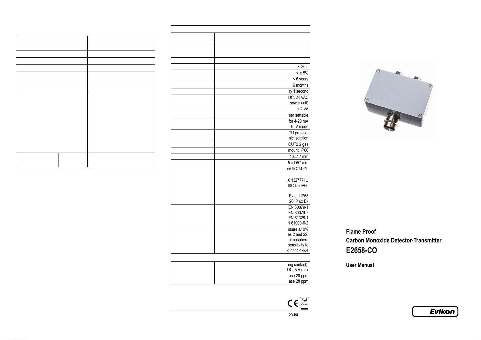
Flame Proof
Carbon Monoxide Detector-Transmitter
E2658-CO
User Manual
PluraSens
®
Evikon MCI OÜ Teaduspargi 7, Tartu info@evikon.eu
Tel. +372 733 6310 50411 Estonia www.evikon.eu
E2658 is a series of flame proof gas detectors-transmitters intended for operation in
8
0
safe zones and ATEX Zones 2 and 22.
E2658 series devices are based on PluraSens® multifunctional platform and provide all
its features.
E2658 series has two independent analog outputs OUT1 and OUT2, user-selectable to
4-20 mA or 0-10 V, proportional either to gas concentration or temperature. RS485
Modbus RTU digital communication interface allows easy instrument configuration and
integration into various automation systems.
An option with relay outputs is available. Two relays RE1 and RE2 with closing contacts
can be used to switch 24 V or 230 V powered alarm sirens, ventilation fans, shut-off
valves or other actuators.
The instruments utilise gas sensors of various types with excellent repeatability, stability
and long lifetime
Please read this manual carefully before operating!
Safety requirements
Always adhere to the safety provisions applicable in the country of use.
Do not perform any maintenance operation with the power on.
Do not let water or foreign objects inside the device.
Make sure that installation and maintenance are performed in the explosion safe
atmosphere.
The device should be properly earthed
It is crucial to tighten properly all the thread connections (screws, cable glands)
Use ATEX certified armoured cables or cable conduits
Avoid strong vibration and mechanical shock
Avoid direct sunlight
Avoid sources of strong electromagnetic interference
Do not use the device in the carbon disulfide atmosphere, since it may damage the
sealing gasket
Although E2658 series devises are suitable for use in the presence of flammable
dust, special precautions should be taken when operating in a dusty environment.
Dust may block the porous filter of the sensor and compromise results of
measurement. The detector should be inspected regularly if used in a dusty
atmosphere.
Choosing location
There are no precise rules or standards to follow when installing the gas detectors. The
following points must be taken into account:
safety: see Safety requirements section,
application (air quality control or leakage detection),
properties of the space under investigation (room geometry, direction and velocity of
air flows etc),
detected gas (relative density to air, whether the gas is flammable, or toxiс, or oxygen
displacing),
safety: strong vibrations, mechanical shock, and the sources of strong
electromagnetic interference should be avoided,
the device should be accessible for maintenance and repair.
For early leakage detection install the sensor as close as possible to the potential
leakage sources (flanges, valves, pressure reducers, pumps, etc), taking into
consideration other points listed above. For general area monitoring without definite
leakage sources, the detectors should be distributed evenly in the room. For personal
safety control the detectors are installed in the breathing zone (at the height of the head
of people or animals). Recommended sensor position is vertical, pointing downwards.
See Installation guidelines section for more information.
Installation and connections
Never perform installation or maintenance in explosive atmosphere!
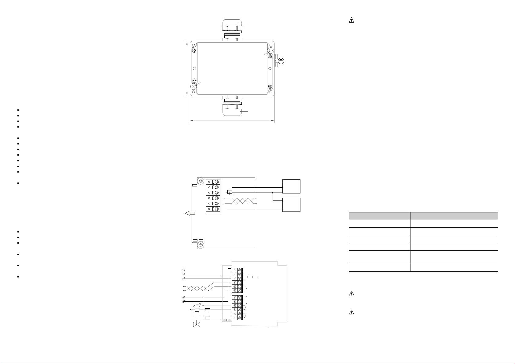
The device is fixed on the wall using two holes located outside the sealed area of the
device (see dimensional drawing below).
M25 (cable entry)
fixing hole (Ø 5mm)
fixing hole (Ø 5mm)
M25 (sensor)
125
1. Unscrew four lid screws and detach the lid from the detector.
2. Fix the detector on the wall and earth the enclosure using earthing terminal on the
side of the device. (This step may be done after the step 3, consider your convenience).
3. Use M25 cable glands to pass the cables of the power supply and of the external
devices. Plug the power cable and connect the analog/relay outputs and/or digital
interface terminals to the relevant devices according to the relevant connection
diagram.
E2658 basic version
Input 1 4-20 mA / 0-10 V
J3
SENSOR
J1 J2
OUT1
OUT2
0V
A
B
+U
Input 4-20 mA / 0-10 V2
Control LED
0V / GND
Fieldbus
+24V
0V
Controller
Power
Supply
E2658 version with relays
J1 J 2
J 3
OUT1
OUT2
Control LED
0V
A
RS48 5
B
+U = 11...30 VD C
L
90...2 65 VAC
N
RE1
RE2
4-20 mA / 0-10 V
4-20 mA / 0-10 V
0V / GND
Fieldbus
24 VDC
S
J1: OUT1 type (open: 4-20 mA; closed: 0-10 V)
J : OUT t ype2 2 (open: 4-20 mA; closed: 0-10 V)
J : 3 return to factory settings
Use ATEX certified armoured cables or cable conduits
The screwless quick connect spring terminals on the E2658 series devices are
suitable for a wide range of wires with cross-section 0,5...1,5 mm2. We recommend
to strip the wire end by 8...9 mm and tin it, or to use the wire end sleeves.
To connect the wire, insert the wire end into terminal hole. To disconnect, push the
spring loaded terminal lever, pull the wire out, and release the lever.
Use twisted pair cable, e.g. LiYY TP 2×2×0,5 mm2 or CAT 5, to connect the device
to RS485 network. Use one pair for A and B wires and the second pair for common
0 V and power +U wires to connect the transmitter to Fieldbus network. Respect
polarity. Overall length of all connections via RS485 interface should not exceed
1200 m.
The type of each analog output can be independently changed between 4-20 mA
and 0-10 V with jumpers J1 (OUT1) and J2 (OUT2).
With closed jumper the output is 0-10 V, with open jumper the output is 4-20 mA.
By default both outputs OUT1 and OUT2 are assigned to gas concentration. The
device has built-in temperature sensor which may be tied to any of the outputs.
Note The outputs are not galvanically isolated from 24 V power supply and share
common 0V. Allowed load resistance limits are stated in Specifications table. To power
the instrument from an external 24 VDC source, connect terminals 0V and +U to the
source. If the integrated mains power supply module is used, connect terminals L and N
to the mains.
Note Actuator short-circuits should be avoided, to protect the instrument relays use
external fuses or safety switches.
The output assignments and scales can be changed by Modbus commands. (See
Annex 1 for more information.)
We recommend to set the difference between the upper and bottom limits of the
output scale not narrower than 20% of detection range (for CO detectors the scales
down to 5% of range are allowed). In any case, do not set the output scale below
the tenfold resolution of the device.
4. Turn on the power. The sensor heating up may take up to five minutes after
switching on. A LED placed on the PCB of the device allows to control the
connection process. The LED response to different processes is presented in the
table below.
Process LED mode
Sensor heating period Blinking 0.5 Hz (50% on, 50% off)
Sensor absence or malfunction Blinking 0.5 Hz (90% off, 10% on)
Relay1 turned on Blinking 1 Hz (50% on, 50% off)
Relay2 turned on Blinking 2 Hz (50% on, 50% off)
Modbus response
The signal is modulated with short on-off pulses,
even single Modbus cycle is traceable*
Normal measurement Continuous light
5. Make sure that the detector is properly fixed, the external devices connected,
power on and control LED is constantly lit. Place the lid back and fix it with the
screws.
Make certain that the cable gland and the screws fixing the front lid are
properly tightened to ensure the conformity to IP66 protection class. and
ATEX requirements
Make certain than the device is properly earthed.
The device is ready to use.
It is recommended to keep the device powered constantly, except for periods of
maintenance and calibration, deplacement etc.
 Loading...