

Page 1
Video Surveillance Systems
Page 2
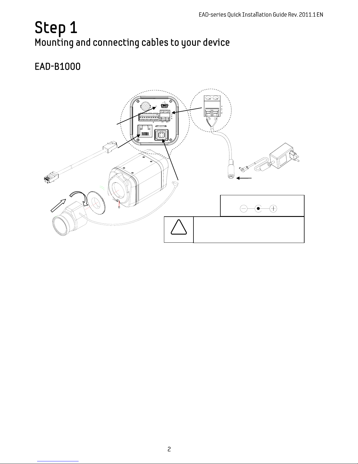
Connect each cable to the device. To see the correct positions of all connectors, refer to the following image:
Proceed to Step 2 when all cables have been connected to your device.
CCW
CW
SET SCREW
LAN
DC 12V
Power Adaptor Connector (DC 12V)
Set Screw
(For IRIS LENS)
Make sure the polarity is correct. Incorrect
connection may cause malfunction or
damage to the device.
Caution
!
RED + -
+
-
CW
ETHERNET
Micro SD
RESET
LOOP OUT
RS-485
DO
DI
AUDIO
-
+
C 1 C
1
Out
In
RESET Button
Page 3
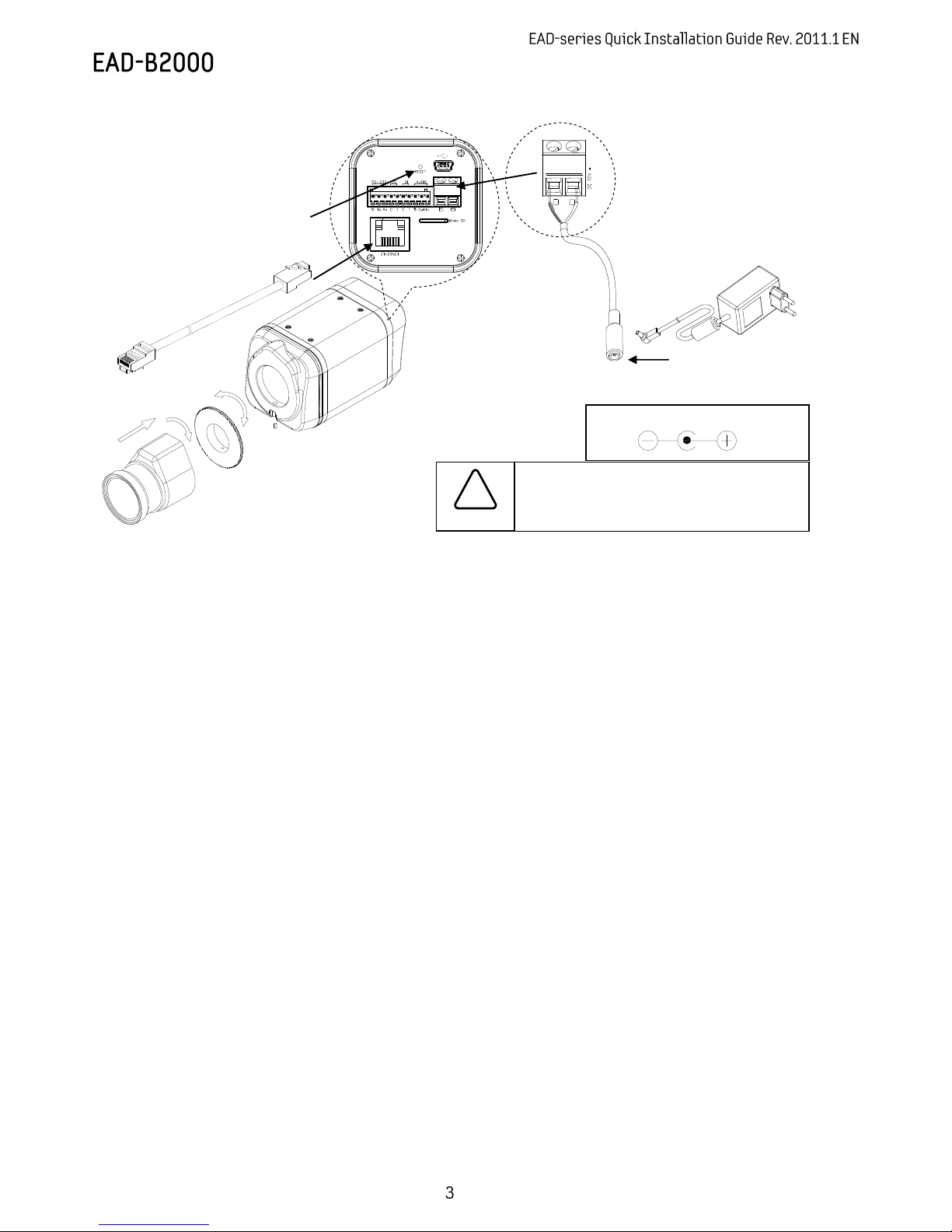
Connect each cable to the device. To see the correct positions of all connectors, refer to the following image:
Proceed to Step 2 when all cables have been connected to your device.
LAN
DC 12V
Power Adaptor Connector (DC 12V)
Make sure the polarity is correct. Incorrect
connection may cause malfunction or
damage to the device.
Caution
!
RED + -
+
-
RESET Button
CCW
CW
SET SCREW
Page 4
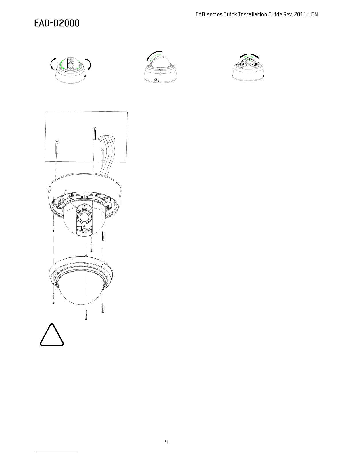
Manual adjustment for 3-axis movements
Before installation, make a manual adjustment on the inner liner. Perform 3-axis movements manually by
turning the inner liner to different directions as above, and check if it moves properly.
1) Connect the LAN cable and power
supply cable with the camera. For the
detailed information, please refer to
the Step2.
2) Place the installation template
(which is included in the package) on
the ceiling.
3) Drill three holes on the template and
insert anchor blocks into the holes.
Fasten the camera with screws.
4) Put the dome cover on the main
body of the camera. Make sure the
main body and the cover fit each other
into place.
5) Fasten the cover with screws.
When assembling the main body of the camera and its dome cover, make sure they
fit each other into place.
The camera may fall off the ceiling even after the proper installation and mounting.
To prevent any accident, make sure the ceiling is firm and stable enough to support
the camera. If any reinforcement is needed, consult with your safety personnel and
proceed with the installation.
Caution
!
Page 5
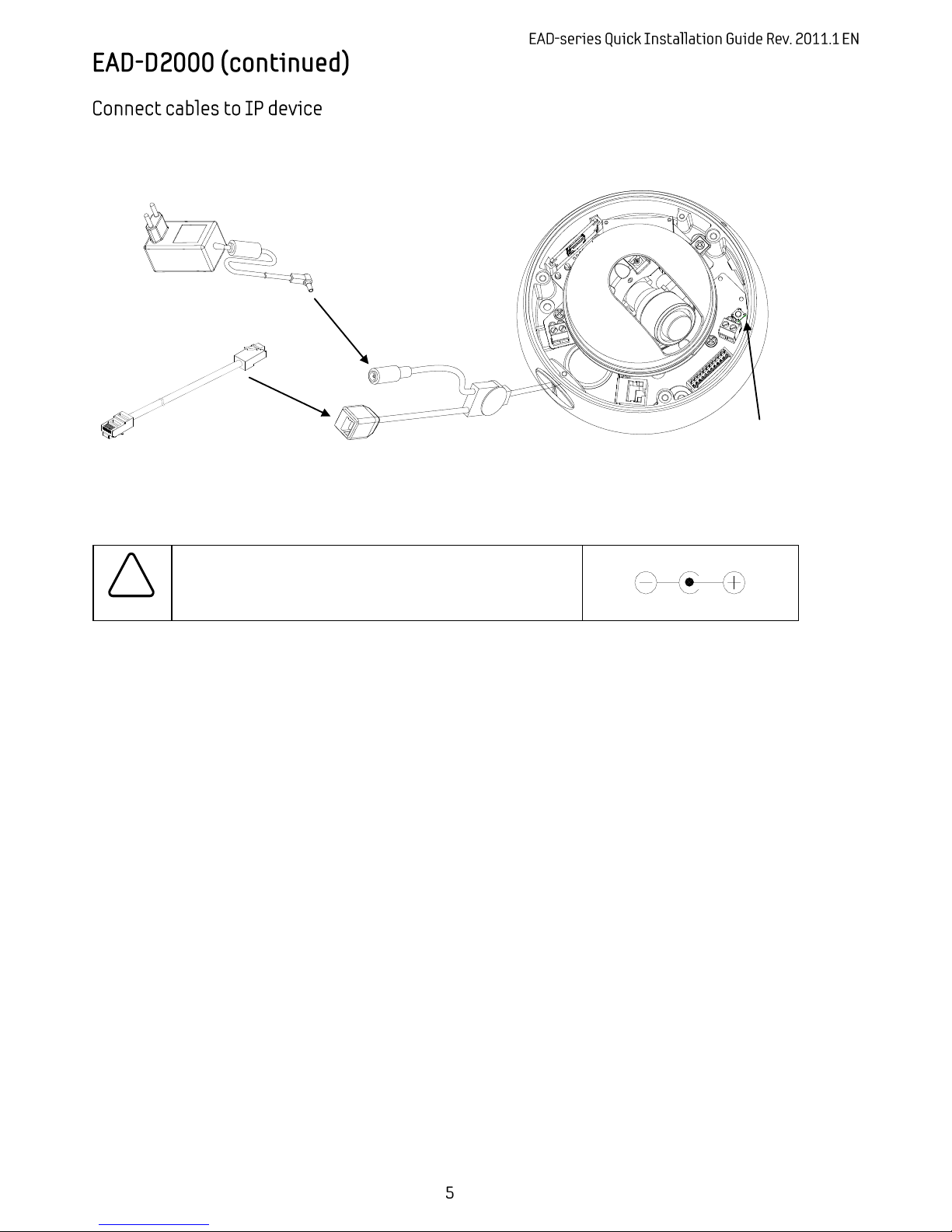
Connect each cable to the device. To see the correct positions of all connectors, refer to the following image
below.
Proceed to Step 2 when all cables have been connected to your device.
LAN
DC 12V
Make sure the polarity is correct. Incorrect connection may
cause malfunction or damage to the IP device.
Caution
!
Power Adaptor Connector (DC 12V)
* Models herein and their appearance
are subject to change without any prior
notice.
Reset Button
Page 6
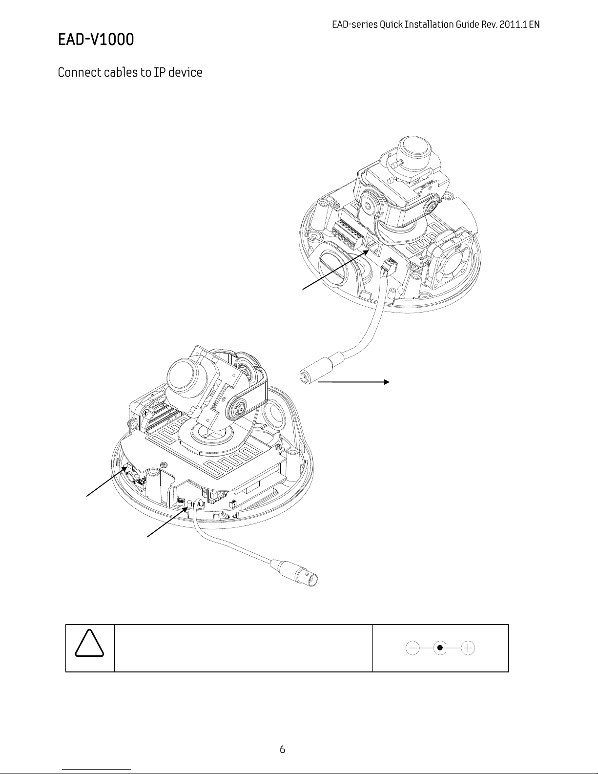
Connect required cables to the device including the power cable, LAN cable, and other optional cables. To
see the correct positions of all connectors, refer to the following image below.
LAN Cable
Make sure the polarity is correct. Incorrect connection may
cause malfunction or damage to the IP device.
Caution
!
Power Adaptor Connector (DC 12V)
Power Cable
(DC 12V)
Reset Button
LEDs
Page 7
Caution
!
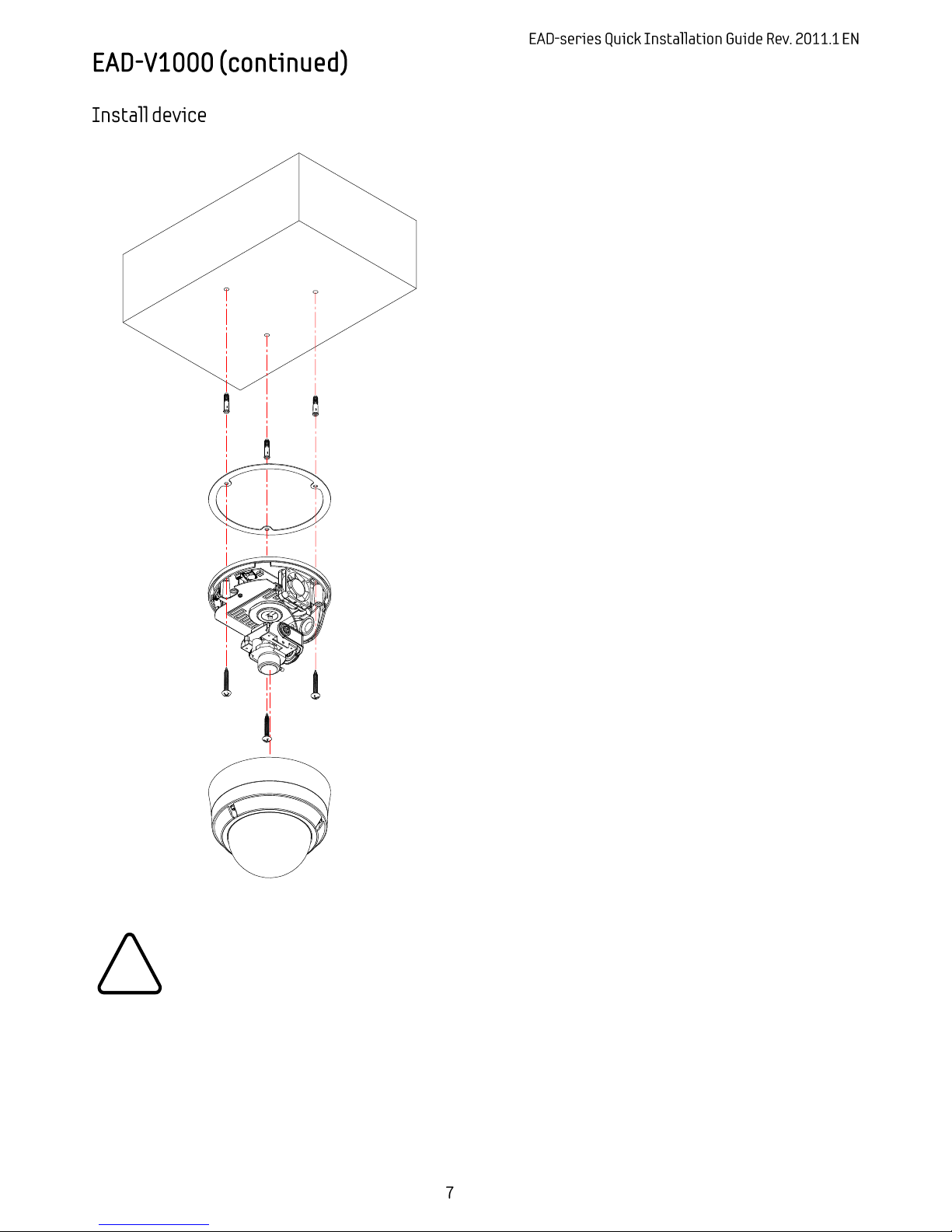
1) Place the installation template that is
provided in the package on the desired
position of installation.
2) Attach the waterproof silicon band
on the bottom plate of the device.
3) Drill three holes on the template and
insert anchor blocks into the holes.
Fasten the camera with screws.
4) Make sure the cables are properly
connected by checking the LEDs. For
the position of the LEDs, please refer to
the Step1.
5) Adjust the lens position by referring to
the Step 3.
6) Put the dome cover on the main
body of the camera. Make sure the
main body and the cover fit each other
into place.
7) Fasten the cover with screws.
When assembling the main body of the camera and its dome cover, make sure they
fit each other into place.
The camera may fall off the ceiling even after the proper installation and mounting.
To prevent any accident, make sure the ceiling is firm and stable enough to support
the camera. If any reinforcement is needed, consult with your safety personnel and
proceed with the installation.
Page 8
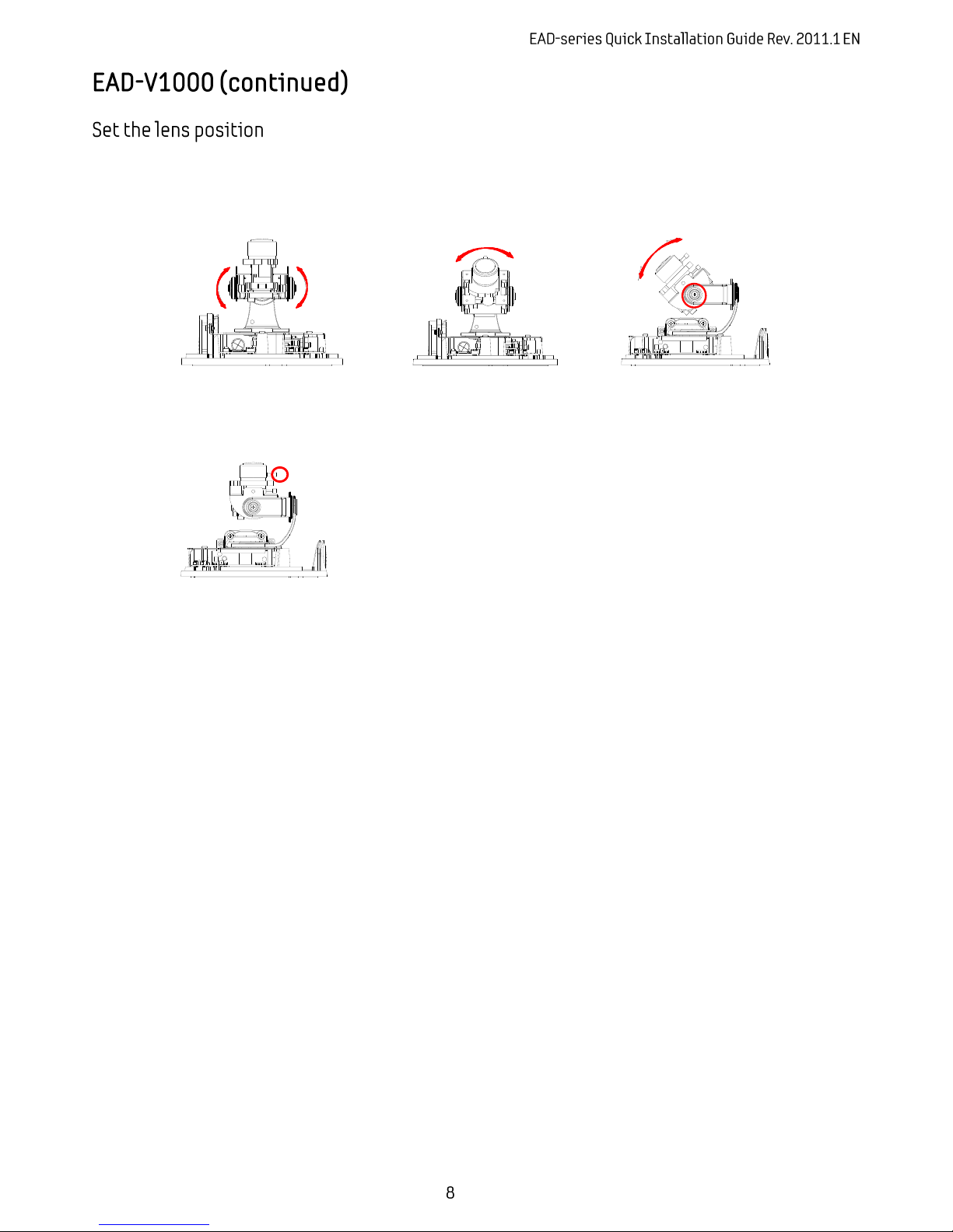
1) Remove the dome cover.
2) Adjust the lens to the desired position by manually moving its body in the following directions.
After adjustment, fasten the screw of the rotation axis.
2) Make a rough adjustment of the lens focus by using its focus puller.
Proceed to Step 2 when all cables have been connected to your device.
B. Left or right movement of
lens body
C. Up or down movement of
lens body
A. Clockwise movement of
lens bottom holder
Page 9
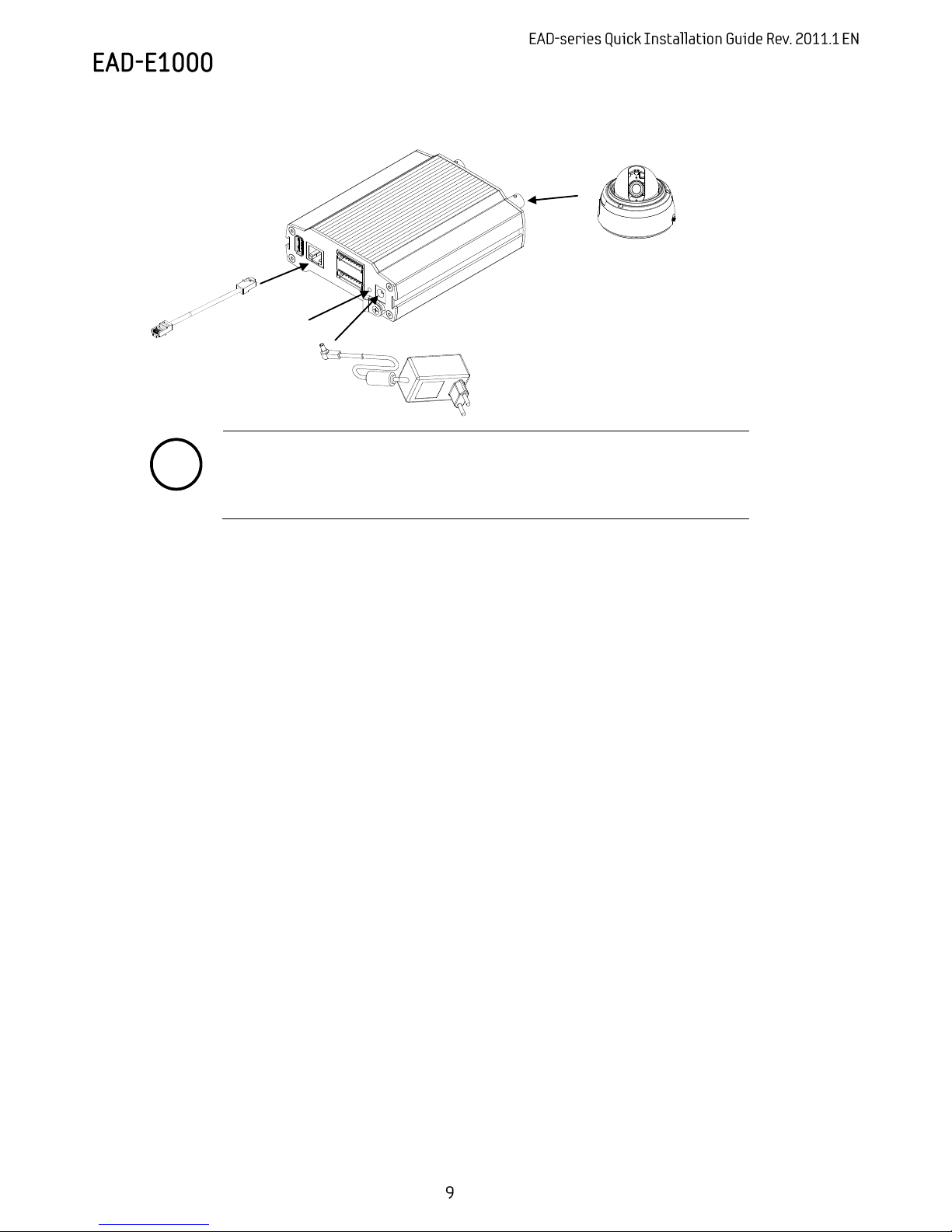
Connect each cable to the device. To see the correct positions of all connectors, refer to the image
below.
Note
i
Make sure to connect the analog video input before you turn on the encoder.
Otherwise, the device must be rebooted to see the normal display if the
camera is NTSC, because the encoder default setting is PAL without a video
connection.
Proceed to Step 2 when all cables have been connected to your device.
DC 12V
* Models herein and their appearance
are subject to change without any prior
notice.
RESET Button
Page 10
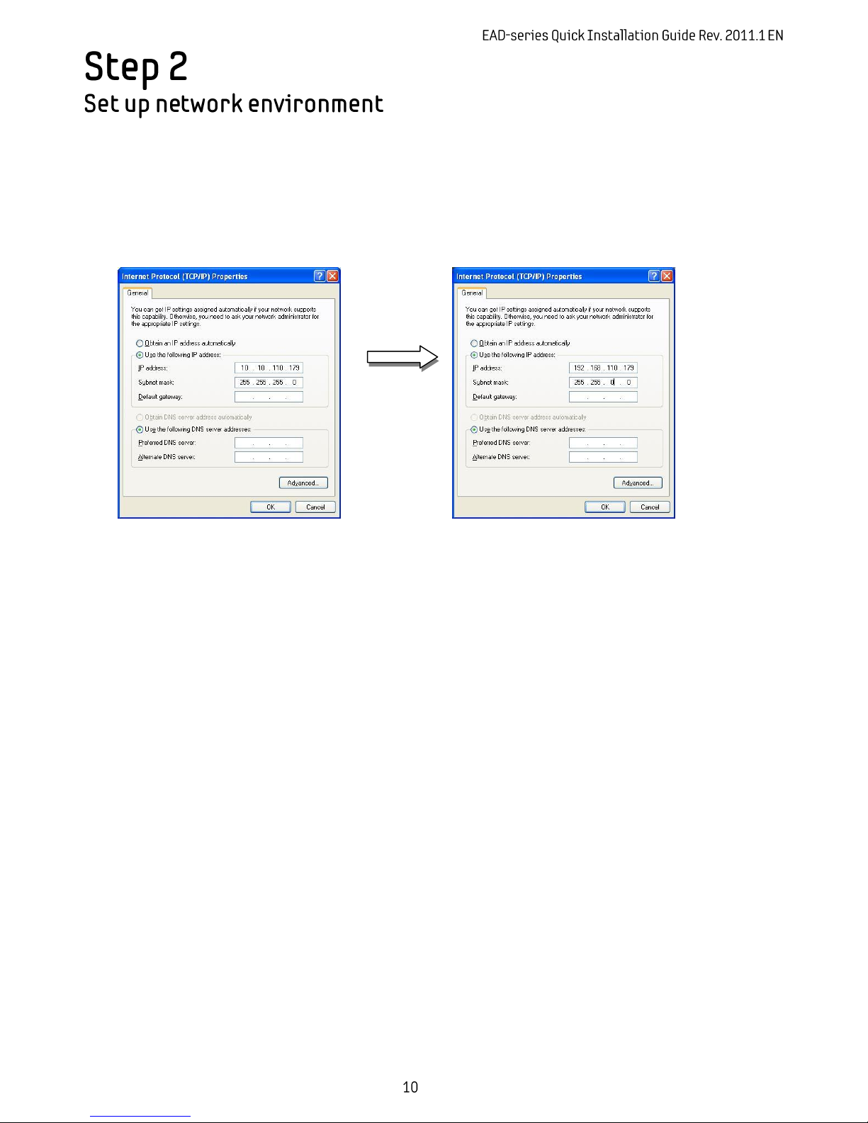
The default IP address of your EAD-device is 192.168.XXX.XXX. You can find the available IP address from the
MAC address of your device. Please make sure the device and your PC are on the same network segment
before running the installation. If the network segment is different between your PC and the device, change
your PC’s settings as below.
IP address : 192.168.xxx.xxx
Subnet mask: 255.255.0.0
Page 11
View the live video on a web page using your EAD-device and its IP address. To have the correct IP address
ready and use it on a web page:
1. Convert a MAC address to an IP address. Refer to the Hexadecimal-Decimal Conversion Chart at the end of
this manual.
(The MAC address is attached on the side or bottom of the device.)
2. Open a web browser and enter the IP address of the device.
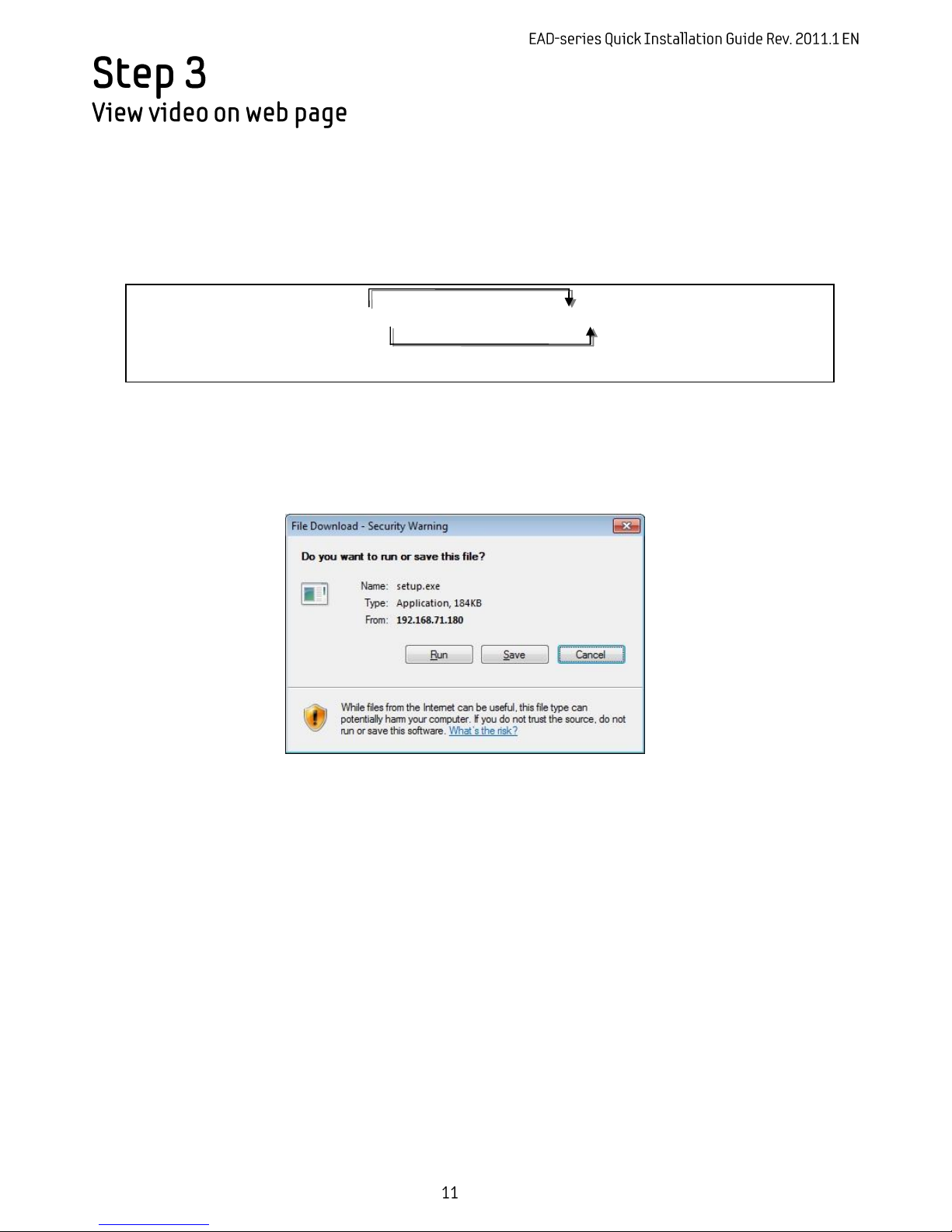
3. Click pop-up blocked and install the ActiveX setup.exe by clicking the Run or Save button. You need to
install the ActiveX for displaying the images.
4. Follow the instructions of the dialog boxes and complete the installation. Then the live video is displayed
on the main page of the web browser.
5. If the live video is not displayed with the message said, “This software requires the Microsoft XML Parser
V6 or higher. Please download MSXML6 from the Microsoft website to continue. Error code: Can not create
XMLDOMDocument.”, please download and install the relevant MSXML.
* The explanation and captured images on this manual are mainly on the basis of Internet Explorer 7.0.
Page 12
To set up the Network configuration:
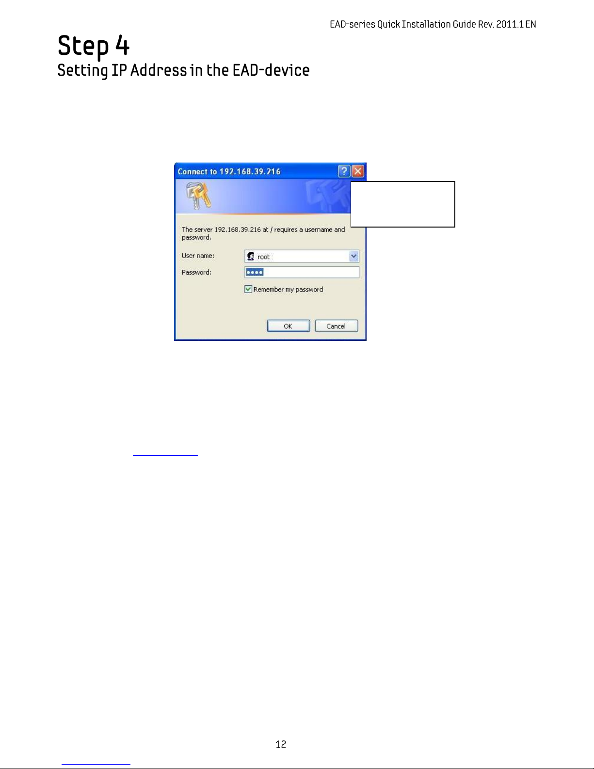
1. Click Setup on the upper right of the web page. The login page is displayed as below.
2. Enter the default user name (root) and the default password (pass), and then select OK.
3. Click System Options on the left of the Setup page, and then select TCP/IP from the drop-down menu.
4. Input the data for the IP address configuration, and click the Apply button on the bottom of the page.
To change the IP address, please make sure to check and have the correct Subnet mask and Gateway ready. To
use DHCP, select Obtain an IP address via DHCP.
To learn how to set up the web page for advanced configuration, refer to the User's Manual, which can be
downloaded from www.evido.info.
The default username
and password are:
root and pass.
Page 13
Once you have completed steps 1-4 you are ready to install a detection license in the device. The license is
based upon the unique Hardware Code available in each device. You can find the Hardware Code of your
device in the web interface.
In the menu tree, select Activation Activate
You will find a Hardware Code similar to the example below:
FA2ED17CDC8E49889D76460157EFB3CCEAEF3ACD83B66F1D11E61B862166A30E
Go to www.evido.info and click on “Request license for EAD-series product”. Enter your contact details
together with the hardware ID in the form displayed on the web page.
Once your request has been processed, a detection license will be created and sent in return to you by e-mail.
Install the detection license received by entering the license code in the Activation Code field.
When the license code has been installed, you can start configuring detection rules by clicking on the VCA
menu item.
Once the detection license has been installed in the EAD-device, you can connect it in your VMS and start
receiving the alarms that has been set up. Documentation for how to connect the EAD-device in the VMS is
available on www.evido.info.
To learn more about the different detection licenses available, or to learn more about using other features and
detection triggers of your device, refer to the manual, which is available at www.evido.info.
Page 14
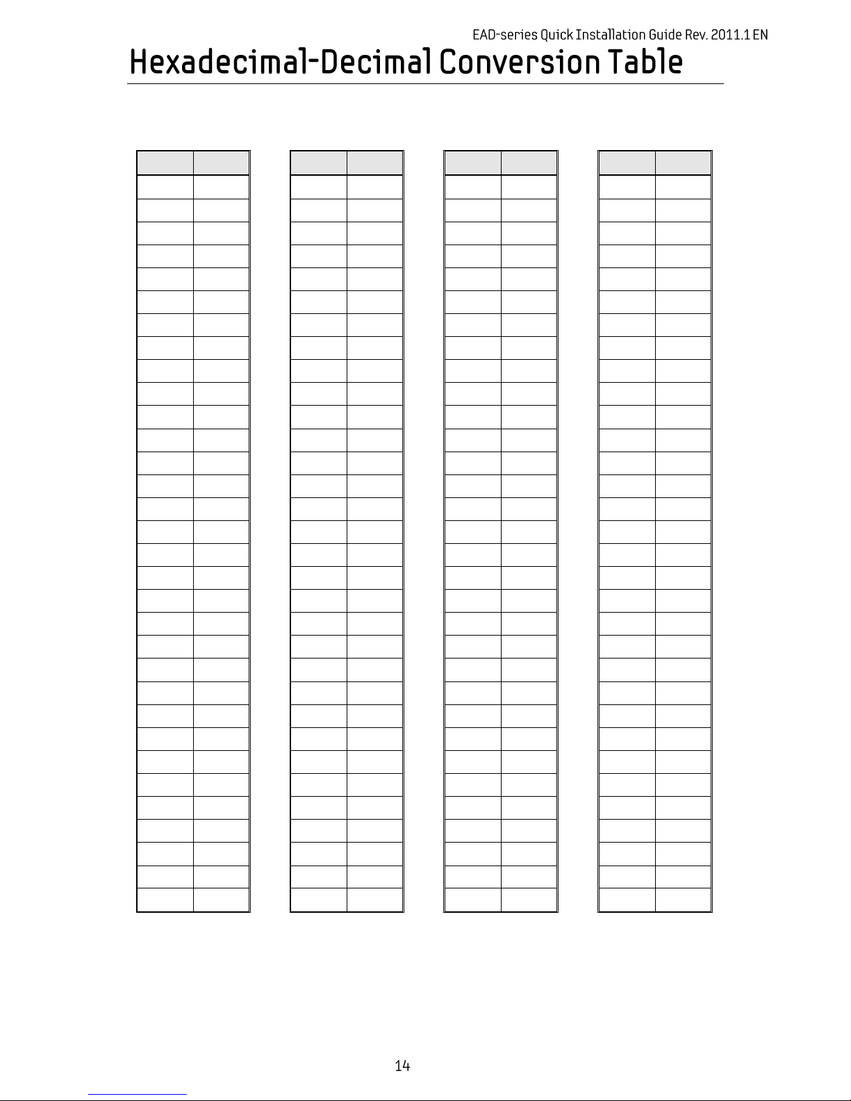
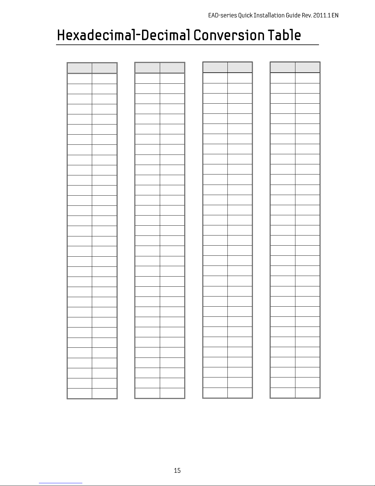
Refer to the following table when you convert the MAC address of your device to IP address.
Hex
Dec
00
0
01 1 02
2
03
3
04
4
05
5
06
6
07
7
08 8 09
9
0A
10
0B
11
0C
12
0D
13
0E
14
0F
15
10
16
11
17
12
18
13
19
14
20
15
21
16
22
17
23
18
24
19
25
1A
26
1B
27
1C
28
1D
29
1E
30
1F
31
Hex
Dec
20
32
21
33
22
34
23
35
24
36
25
37
26
38
27
39
28
40
29
41
2A
42
2B
43
2C
44
2D
45
2E
46
2F
47
30
48
31
49
32
50
33
51
34
52
35
53
36
54
37
55
38
56
39
57
3A
58
3B
59
3C
60
3D
61
3E
62
3F
63
Hex
Dec
40
64
41
65
42
66
43
67
44
68
45
69
46
70
47
71
48
72
49
73
4A
74
4B
75
4C
76
4D
77
4E
78
4F
79
50
80
51
81
52
82
53
83
54
84
55
85
56
86
57
87
58
88
59
89
5A
90
5B
91
5C
92
5D
93
5E
94
5F
95
Hex
Dec
60
96
61
97
62
98
63
99
64
100
65
101
66
102
67
103
68
104
69
105
6A
106
6B
107
6C
108
6D
109
6E
110
6F
111
70
112
71
113
72
114
73
115
74
116
75
117
76
118
77
119
78
120
79
121
7A
122
7B
123
7C
124
7D
125
7E
126
7F
127
Page 15
Hex
Dec
80
128
81
129
82
130
83
131
84
132
85
133
86
134
87
135
88
136
89
137
8A
138
8B
139
8C
140
8D
141
8E
142
8F
143
90
144
91
145
92
146
93
147
94
148
95
149
96
150
97
151
98
152
99
153
9A
154
9B
155
9C
156
9D
157
9E
158
9F
159
Hex
Dec
A0
160
A1
161
A2
162
A3
163
A4
164
A5
165
A6
166
A7
167
A8
168
A9
169
AA
170
AB
171
AC
172
AD
173
AE
174
AF
175
B0
176
B1
177
B2
178
B3
179
B4
180
B5
181
B6
182
B7
183
B8
184
B9
185
BA
186
BB
187
BC
188
BD
189
BE
190
BF
191
Hex
Dec
C0
192
C1
193
C2
194
C3
195
C4
196
C5
197
C6
198
C7
199
C8
200
C9
201
CA
202
CB
203
CC
204
CD
205
CE
206
CF
207
D0
208
D1
209
D2
210
D3
211
D4
212
D5
213
D6
214
D7
215
D8
216
D9
217
DA
218
DB
219
DC
220
DD
221
DE
222
DF
223
Hex
Dec
E0
224
E1
225
E2
226
E3
227
E4
228
E5
229
E6
230
E7
231
E8
232
E9
233
EA
234
EB
235
EC
236
ED
237
EE
238
EF
239
F0
240
F1
241
F2
242
F3
243
F4
244
F5
245
F6
246
F7
247
F8
248
F9
249
FA
250
FB
251
FC
252
FD
253
FE
254
FF
255
Page 16
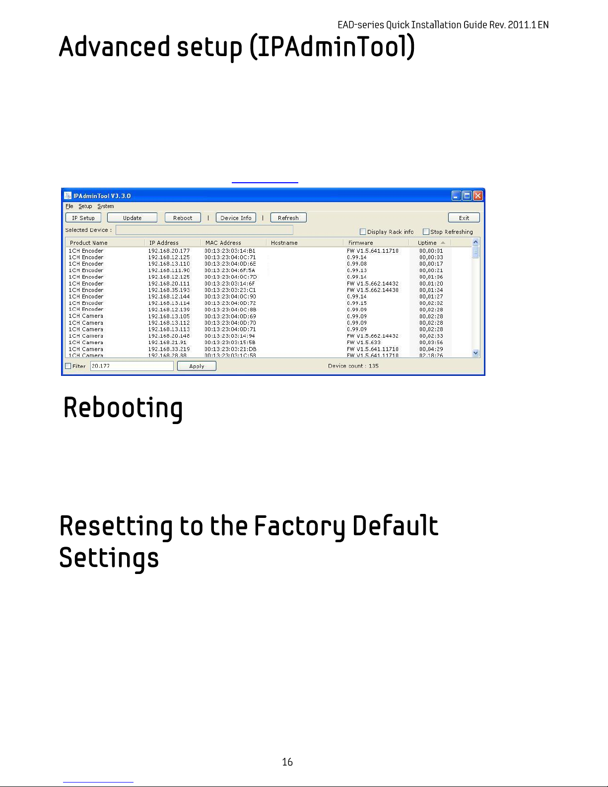
IPAdminTool is a utility program for EAD-products. Following list shows a part of features that IPAdminTool
provides.
Configure IP address, Subnet mask and Gateway
Shows network related information such as MAC address
Updates firmware
Reboots the device
IPAdminTool is available for download at www.evido.info.
Reset can be carried out as follows:
1. While the device is in use, press and hold the Reset.
2. Release the Reset button after 3 seconds.
3. Wait for the system to reboot.
This will reset all parameters, including the IP address, to the Factory Default initialization.
To perform the Factory Default settings:
1. Disconnect the power supply from the device.
2. Connect the power to the device with the Reset button pressed and held.
3. Release the Reset button after 5 seconds.
4. Wait for the system to reboot.
 Loading...