

Evidence Cross-8/HPoE-10G User Manual

Cross-8/HPoE-10G
GUI User Guide
10-Ports L2+ Managed GbE PoE+ Switch
Release A2
2018, Manufacture Corporation. All rights reserved. All brand and product names are trademarks or registered
trademarks of their respective companies
2

About This Manual
Copyright
Copyright © 2018 Manufacture Technology Corp. All rights reserved.
The products and programs described in this User Guide are licensed products of Manufacture
Technology, This User Guide contains proprietary information protected by copyright, and this
User Guide and all accompanying hardware, software and documentation are copyrighted. No
parts of this User Guide may be copied, photocopied, reproduced, translated or reduced to any
electronic medium or machine-readable from by any means by electronic or mechanical.
Including photocopying, recording, or information storage and retrieval systems, for any purpose
other than the purchaser’s personal use, and without the prior express written permission of
Manufacture Technology.
.
Purpose
This GUI user guide gives specific information on how to operate and use the management
functions of the Cross-8/HPoE-10G via HTTP/HTTPs web browser
Audience
The Manual is intended for use by network administrators who are responsible for operating
and maintaining network equipment; consequently, it assumes a basic working knowledge of
general switch functions, the Internet Protocol (IP), and Hypertext Transfer Protocol (HTTP).
CONVENTIONS
The following conventions are used throughout this manual to show information.
WARRANTY
See the Customer Support/ Warranty booklet included with the product. A copy of the specific
warranty terms applicable to your Manufacture products and replacement parts can be
obtained from your Manufacture Sales and Service Office authorized dealer.
Disclaimer
Manufacture Technology does not warrant that the hardware will work properly in all
environments and applications, and marks no warranty and representation, either implied or
expressed, with respect to the quality, performance, merchantability, or fitness for a particular
purpose. Manufacture disclaims liability for any inaccuracies or omissions that may have
occurred. Information in this User Guide is subject to change without notice and does not
represent a commitment on the part of Manufacture. Manufacture assumes no responsibility for
any inaccuracies that may be contained in this User Guide. Manufacture makes no commitment
to update or keep current the information in this User Guide, and reserves the righter to make
improvements to this User Guide and /or to the products described in this User Guide, at any
time without notice.
3


Table of Contents
.......................................................................... ......................................... ......................................... ......... II
ABOUT THIS MANUAL............................................................................ ................................................. II
Revision History............................................................................................................................................ix
INTRODUCTION............................................................................ ............................................................ 1
CHAPTER 1 OPERATION OF WEB-BASED MANAGEMENT.......................... .....................................3
CHAPTER 2 SYSTEM.................................. ......................................... ......................................... .......... 5
2-1 SYSTEM INFORMATION....................................................................................................................................5
2-2 IP ADDRESS.................................................................................................................................................8
2-2.1 Settings................................................................................................................................................8
2-2.2 Advanced Settings............................................................................................................................ 10
2-2.3 Status.................................................................................................................................................14
2-3 SYSTEM TIME....................................................................................................................................... ...... 18
2-4 LLDP........................................................................... ............................................................................. 21
2-4.1 LLDP Configuration..........................................................................................................................21
2-4.2 LLDP-MED Configuration................................................................................................................24
2-4.3 LLDP Neighbour...............................................................................................................................32
2-4.4 LLDP-MED Neighbour......................................................................................................................34
2-4.5 LLDP Neighbour PoE........................................................................................................................38
2-4.6 LLDP Neighbour EEE................................................................................................................ ........40
2-4.7 LLDP Statistics...................................................................................................................................42
2-5 UPNP............................................................................................................................... ........................ 44
CHAPTER 3 PORT MANAGEMENT................................................................................................. ... 45
3-1 PORT CONFIGURATION................................................................................................... ............................ 45
3-2 PORT STATISTICS......................................................................... ............................................................... 48
3-3 SFP PORT INFO..................................................................... .................................................................... 52
3-4 ENERGY EFFICIENT ETHERNET.............................................................................................................. ........ 54
3-5 LINK AGGREGATION................................................................................................................................... 55
3-5.1 Static Configuration.........................................................................................................................55
3-5.2 LACP Configuration..........................................................................................................................57
3-5.3 System Status....................................................................................................................................59
3-5.4 Internal Status...................................................................................................................................60
3-5.5 Neighbor Status................................................................................................................................62
3-5.6 Port Status.........................................................................................................................................64
3-6 LOOP PROTECTION.....................................................................................................................................66
3-6.1 Configuration....................................................................................................................................66
3-6.2 Status.................................................................................................................................................68
3-7 UDLD.......................................................................................... ............................................................. 70
3-7.1 UDLD Configuration.........................................................................................................................70
3-7.2 UDLD Status......................................................................................................................................72
CHAPTER 4 POE MANAGEMENT................................. ......................................... ............................. 74
4-1 POE CONFIGURATION............................................... ................................................................................. 74
4-2 POE STATUS.............................................................................................................................................. 77
4-3 POE POWER DELAY......................................................................................................... ...........................79
4-4 POE AUTO CHECKING................................................................................................. ............................... 80
4-5 POE SCHEDULEING PROFILE......................................................................................................... ...............8 2
CHAPTER 5 VLAN MANAGEMENT.......................... ......................................... ................................. 84
5-1 VLAN CONFIGURATION.............................................................. ............................................................... 84
5-2 VLAN MEMBERSHIP.......................................................................................... ........................................ 88

5-3 VLAN PORT STATUS........................................................................................................ ..........................90
5-4 MAC-BASED VLAN................................................................................................................ ................... 92
5-4.1 Configuration....................................................................................................................................92
5-4.2 Status.................................................................................................................................................94
5-5 PROTOCOL-BASED VLAN................................................................... ........................................................ 95
5-5.1 Protocol to Group.............................................................................................................................95
5-5.2 Group to VLAN.................................................................................................................................98
5-6 IP SUBNET-BASED VLAN...................................................................................... ................................... 100
5-7 GVRP...................................................................................... ............................................................... 102
5-8 PRIVATE VLAN............................................................................ ............................................................ 104
5-9 PORT ISOLATION................................................................................................. .....................................106
5-10 VOICE VLAN................................................................................ ......................................................... 107
5-10.1 Configuration................................................................................................................................107
5-10.2 OUI.................................................................................................................................................109
CHAPTER 6 QUALITY OF SERVICE.............................. ......................................... ............................ 111
6-1 PORT CLASSIFICATION............................................................... ............................................................... 111
6-2 PORT POLICERS........................................................................................................................................ 114
6-3 PORT SHAPERS........................................................................................................................................ 116
6-4 STORM CONTROL..................................................................................................................................... 118
6-5 PORT SCHEDULER............................................................................................................ .........................120
6-6 PORT PCP REMARKING....................................................................................... .....................................122
6-7 DSCP...................................................................................................... ............................................... 124
6-7.1 Port DSCP........................................................................................................................................124
6-7.2 DSCP Translation............................................................................................................................126
6-7.3 DSCP Classification........................................................................................................................128
6-7.4 DSCP-Based QoS............................................................................................................................130
6-8 QOS CONTROL LIST................................................................................................................................. 132
6-8.1 Configuration..................................................................................................................................132
6-8.2 Status...............................................................................................................................................137
6-9 QOS STATISTICS.................................................................... ................................................................... 139
6-10 WRED.......................................................................................... ........................................................ 140
CHAPTER 7 SPANNING TREE..................................................................... ...................................... 142
7-1 STP CONFIGURATION....................................................................... ........................................................ 142
7-2 MSTI CONFIGURATION.......................................................................................................... .................. 145
7-3 STP STATUS............................................................................................ .................................................149
7-4 PORT STATISTICS...................................................................................................................................... 153
CHAPTER 8 MAC ADDRESS TABLES.................................................................... ............................ 155
8-1 CONFIGURATION.......................................................................... ............................................................ 155
8-2 INFORMATION............................................................................................................. ............................. 158
CHAPTER 9 MULTICAST............................... ......................................... .......................................... . 160
9-1 IGMP SNOOPING..................................................................................................... ............................... 160
9-1.1 Basic Configuration........................................................................................................................160
9-1.2 VLAN Configuration.......................................................................................................................163
9-1.3 Status...............................................................................................................................................165
9-1.4 Group Information..........................................................................................................................167
9-1.5 IGMP SFM Information...................................................................................................................169
9-2 MLD SNOOPING............................................................................... ...................................................... 171
9-2.1 Basic Configuration........................................................................................................................171
9-2.2 VLAN Configuration.......................................................................................................................174
9-2.3 Status...............................................................................................................................................176
9-2.4 Groups Information........................................................................................................................178
9-2.5 MLD SFM Information....................................................................................................................180

9-3 MVR...................................................................................... ................................................................ 182
9-3.1 Basic Configuration........................................................................................................................182
9-3.2 Statistics...........................................................................................................................................185
9-3.3 Groups Information........................................................................................................................187
9-3.4 SFM Information.............................................................................................................................189
9-4 MULTICAST FILTERING PROFILE................................................................................... ............................... 191
9-4.1 Filtering Profile Table.....................................................................................................................191
9-4.2 Filtering Address Entry...................................................................................................................194
CHAPTER 10 DHCP................................ ......................................... ......................................... .......... 196
10-1 SNOOPING............................................................................................. ............................................... 196
10-1.1 Configuration................................................................................................................................196
10-1.2 Snooping Table.................................................................................................................. ...........198
10-1.3 Detailed Statistics.........................................................................................................................200
10-2 RELAY............................................................................................... ..................................................... 202
10-2.1 Configuration................................................................................................................................202
10-2.2 Statistics.........................................................................................................................................204
10-3 SERVER................................................................................................. ................................................. 206
10-3.1 Configuration................................................................................................................................206
10-3.2 Status.............................................................................................................................................208
CHAPTER 11 SECURITY....................................................................... .............................................. 209
11-1 MANAGEMENT....................................................................................................................................... 209
11-1.1 Account..........................................................................................................................................209
11-1.2 Privilege Levels..............................................................................................................................211
11-1.3 Auth Method.................................................................................................................................212
11-1.4 Access Method..............................................................................................................................215
11-1.5 HTTPS............................................................................................................................................217
11-2 802.1X....................................................................................................................................................219
11-2.1 Configuration................................................................................................................................219
11-2.2 Status.............................................................................................................................................227
11-3 IP SOURCE GUARD................................................................................................................................ 229
11-3.1 Configuration................................................................................................................................229
11-3.2 Static Table....................................................................................................................................231
11-3.3 Dynamic Table..............................................................................................................................233
11-4 ARP INSPECTION..................................................................................................... .............................. 235
11-4.1 Configuration................................................................................................................................235
11-4.2 VLAN Configuration.....................................................................................................................237
11-4.3 Static Table....................................................................................................................................239
11-4.4 Dynamic Table..............................................................................................................................241
11-5 PORT SECURITY...................................................................................................................................... 243
11-5.1 Configuration................................................................................................................................243
11-5.2 Status.............................................................................................................................................246
11-6 RADIUS.......................................................................................... ..................................................... 249
11-6.1 Configuration................................................................................................................................249
11-6.2 Status.............................................................................................................................................252
11-7 TACACS+............................................................................................................................................ 257
CHAPTER 12 ACCESS CONTROL...................................................................... ................................ 259
12-1 PORTS CONFIGURATION.................................................... ..................................................................... 259
12-2 RATE LIMITERS....................................................................................................................................... 261
12-3 ACCESS CONTROL LIST........................................................................................................................... 263
12-4 ACL STATUS.......................................................................................................................................... 275
CHAPTER 13 SNMP................................ ......................................... .................................................. 277
13-1 CONFIGURATION........................................................................................ ............................................ 277

13-2 SNMPV3.................................................................................................................................................279
13-2.1 Communities.................................................................................................................................279
13-2.2 Users...................................................................................................................................... ........281
13-2.3 Groups........................................................................................................................................... 283
13-2.4 Views..............................................................................................................................................285
13-2.5 Access.............................................................................................................................................287
13-3 STATISTICS........................................................................... .................................................................. 289
13-3.1 Configuration................................................................................................................................289
13-3.2 Status.............................................................................................................................................291
13-4 HISTORY........................................................................................................... ..................................... 294
13-4.1 Configuration................................................................................................................................294
13-4.2 Status.............................................................................................................................................296
13-5 ALARM......................................................................................... ......................................................... 298
13-5.1 Configuration................................................................................................................................298
13-5.2 Status.............................................................................................................................................301
13-6 EVENT................................................................................................................................. .................. 303
13-6.1 Configuration................................................................................................................................303
13-6.2 Status.............................................................................................................................................305
CHAPTER 14 MEP................................. ......................................... .................................... ................ 307
14-1 MEP CONFIGURATION............................................................... ............................................................307
CHAPTER 15 ERPS....................................................................... ...................................................... 309
CHAPTER 16 PTP................................. ......................................... ..................................................... 311
16-1 CONFIGURATION........................................................................................ ............................................ 311
16-2 STATUS............................................................................................................. ..................................... 313
CHAPTER 17 EVENT NOTIFICATION........................... ......................................... ........................... 315
17-1 SNMP TRAP................................................................. ........................................................................ 315
17-2 EMAIL................................................................................................................................................... 318
17-3 LOG............................................................................................ .......................................................... 320
17-3.1 Syslog.............................................................................................................................................320
17-3.2 View Log........................................................................................................................................322
17-4 DIGITAL I/O........................................................................................................................................... 324
17-5 EVENT CONFIGURATION................................................................................................................ ......... 325
CHAPTER 18 DIAGNOSTICS............................... ......................................... ..................... ................ 327
18-1 PING..................................................................................................................................................... 327
18-2 TRACEROUTE.......................................................................................................................................... 329
18-3 CABLE DIAGNOSTICS............................................................. ................................................................. 331
18-4 MIRRORING........................................................................ ................................................................... 333
18-5 SFLOW.................................................................. ................................................................................ 335
18-5.1 Configuration................................................................................................................................335
18-5.2 Statistics.........................................................................................................................................338
CHAPTER 19 MAINTENANCE......................................................................... .................................. 340
19-1 CONFIGURATION........................................................................................ ............................................ 340
19-1.1 Save startup-config......................................................................................................................340
19-1.2 Backup...........................................................................................................................................342
19-1.3 Restore...........................................................................................................................................343
19-1.4 Activate..........................................................................................................................................345
19-1.5 Delete.............................................................................................................................................346
19-2 RESTART DEVICE........................................................................... ......................................................... 347
19-3 FACTORY DEFAULTS................................................................................................................................ 348
19-4 FIRMWARE................................................................................................................... .......................... 349
19-4.1 Firmware Upgrade.......................................................................................................................349

19-4.2 Firmware Selection.......................................................................................................................350

Revision History

INTRODUCTION
Overview
In this User Guide, it will not only tell you how to install and connect your network system but
configure and monitor the Cross-8/HPoE-10G through the web by (RJ-45) serial interface and
Ethernet ports step-by-step. Many explanations in detail of hardware and software functions are
shown as well as the examples of the operation for web-based interface.
The Cross-8/HPoE-10G are the next generation Industrial L2+ managed GbE PoE+ switch from
Manufacture, is a portfolio of affordable managed switches that provides a reliable infrastructure for
your business network. These switches deliver more intelligent features you need to improve the
availability of your critical business applications, protect your sensitive information, and optimize
your network bandwidth to deliver information and applications more effectively. It provides the
ideal combination of affordability and capabilities for entry level networking includes small business
or enterprise application and helps you create a more efficient, better-connected workforce.
Cross-8/HPoE-10G L2+ Managed GbE PoE+ Switch provide 10 ports in a single device; the
specification is highlighted as follows.
L2+ features provide better manageability, security, QoS, and performance.
Support IPv4/IPv6 dual stack management
Support SSH/SSL secured management
Support SNMP v1/v2c/v3
Support RMON groups 1,2,3,9
Support sFlow
Support IGMP v1/v2/v3 Snooping
Support MLD v1/v2 Snooping
Support RADIUS and TACACS+ authentication
Support IP Source Guard
Support DHCP Relay (Option 82)
Support DHCP Snooping
Support ACL and QCL for traffic filtering
Support 802.1d(STP), 802.1w(RSTP) and 802.1s(MSTP)
Support LACP and static link aggregation
Support Q-in-Q double tag VLAN
Support GVRP dynamic VLAN
1
Release Date Revision
Initial Release 2018/09/06 A1
2018/12/21 A2

Overview of this User Guide
Chapter 1 “Operation of Web-based Management”
Chapter 2 “System”
Chapter 3 “Port Management”
Chapter 4 “PoE Management”
Chapter 5 “VLAN Management”
Chapter 6 “Quality of Service”
Chapter 7 “Spanning tree”
Chapter 8 “MAC Address Tables”
Chapter 9 “Multicast”
Chapter 10 “DHCP”
Chapter 11 “Security”
Chapter 12 “Access Control”
Chapter 13 “SNMP”
Chapter 14 “MEP”
Chapter 15 “ERPS”
Chapter 16 “PTP”
Chapter 17 “Event Notification”
Chapter 18 “Diagnostics”
Chapter 19 “Maintenance”
Ordering information
Variable N=10
Variable Y=8

Chapter 1 Operation of Web-based Management
Initial
Configuration
This chapter instructs you how to configure and manage the
Cross-8/HPoE-10G through the web user interface. With this
facility, you can easily access and monitor through any one port
of the switch all the status of the switch, including MIBs status,
each port activity, Spanning tree status, port aggregation status,
multicast traffic, VLAN and priority status, even illegal access
record and so on.
The default values of the Cross-8/HPoE-10G are listed in the table below:
IP Address 192.168.1.1
Subnet Mask 255.255.255.0
Default Gateway 192.168.1.254
Username Admin
Password 1234
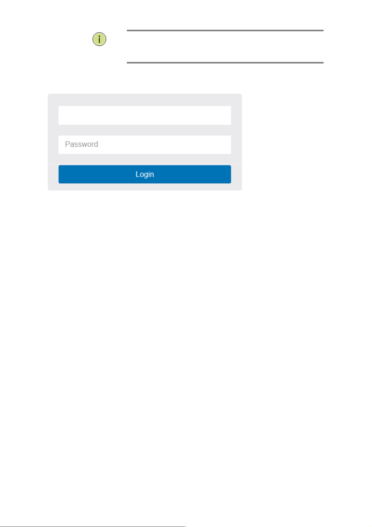
After the Cross-8/HPoE-10G has been finished configuration it interface, you can
browse it. For instance, type
http://192.168.1.1 in the address row in a browser, it
will show the following screen and ask you inputting username and password in
order to login and access authentication.
The default username is “Admin” and password is 1234. For the first time to use,
please enter the default username and password, and then click the <Login> button.
The login process now is completed. In this login menu, you have to input the
complete username and password respectively, the Cross-8/HPoE-10G will not give
you a shortcut to username automatically. This looks inconvenient, but safer.
In the Cross-8/HPoE-10G, allowed two or more users using administrator’s identity to
manage this switch, which administrator to do the last setting, it will be an available
configuration to effect the system.
NOTE:
When you login the Switch WEB page to manage. You must first type the
Username of the admin. Password was blank, so when you type after the
end Username, please press enter. Management page to enter WEB.
When you login Cross-8/HPoE-10G series switch Web UI management, you
can use both ipv4 ipv6 login to manage
To optimize the display effect, we recommend you use Microsoft IE 6.0
above, Netscape V7.1 above or Firefox V1.00 above and have the resolution
1024x768. The switch supported neutral web browser interface
3
NOTE:
AS Cross-8/HPoE-10G the function enable dhcp, so If you do not have
DHCP server to provide ip addresses to the switch, the Switch default ip
192.168.1.1
Figure 1: The login page
4
Chapter 2 System
This chapter describes the entire basic configuration tasks which includes the System
Information and any manage of the Switch (e.g. Time, Account, IP, Syslog and NTP.)
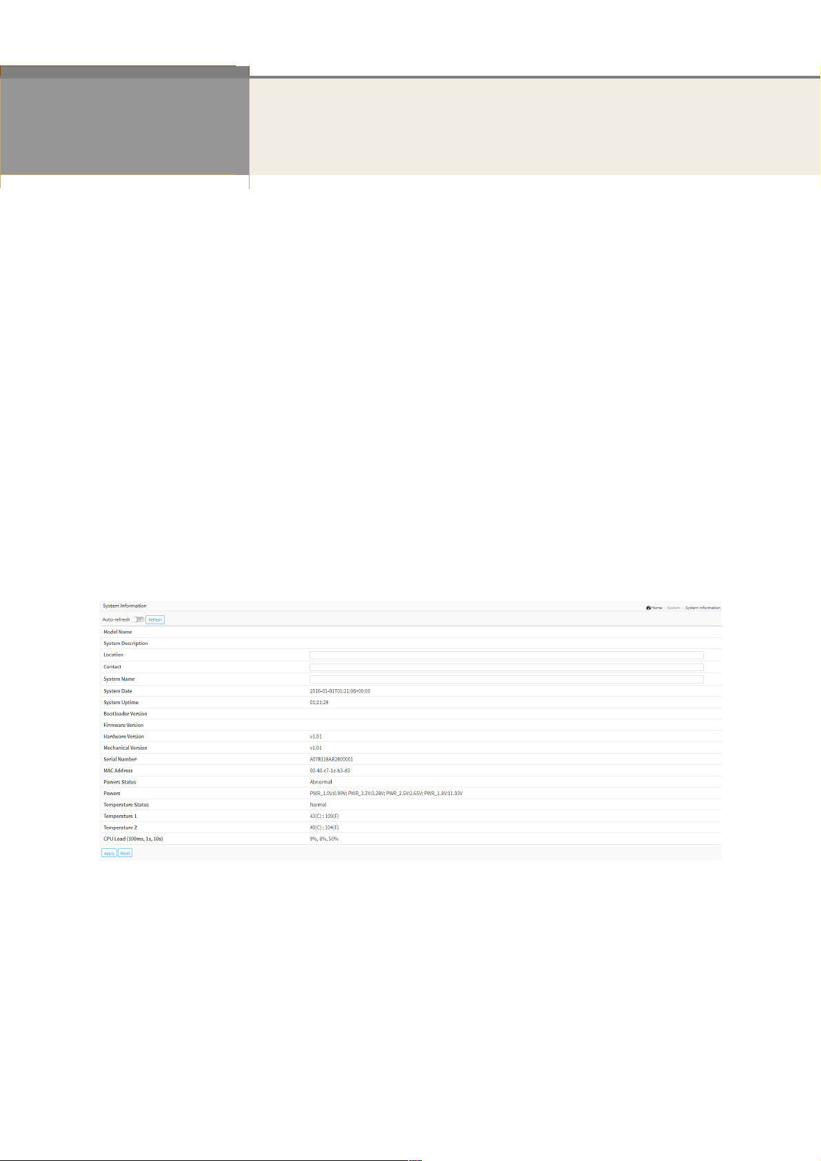
2-1 System Information
You can identify the system by configuring system name, location and the contact of the
switch.
The switch system’s contact information is provided here.
Web interface
To configure System Information in the web interface:
1. Click System and System Information.
2. Write System Name, Location, Contact information in this page.
3. Click Apply
Figure 2-1: System Information
Parameter description:
Model Name :
Displays the factory defined model name for identification purpose.
System Description :
Displays the system description.
Location :
The system location configured in Configuration | System | Information | System Location.

Contact :
The system contact configured in Configuration | System | Information | System Contact.
System name :
Displays the user-defined system name that configured in System | System Information |
Configuration | System Name.
System Date :
The current (GMT) system time and date. The system time is obtained through the Timing
server running on the switch, if any.
System Uptime :
The period of time the device has been operational.
Bootloader Version :
Displays the current boot loader version number.
Firmware Version :
The software version of this switch.
Hardware Version :
Displays the hardware version of the device.
Mechanical Version :
Displays the mechanical version of the device.
Series Number :
The serial number of this switch.
MAC Address :
The MAC Address of this switch.
Powers Status :
Displays the powers status of the system.
Powers :
Displays the powers of the system.
Temperature Status :
Displays the temperature status of the system.
Temperature 1 :
Displays the temperature 1 of the system.
Temperature 2 :
Displays the temperature 2 of the system.
CPU Load (100ms, 1s, 10s) :
Displays the cpu loading(100ms, 1s, 10s) of the system.
Buttons
Apply :
Click to save changes.
Reset :
Click to undo any changes made locally and revert to previously saved values.
Refresh :

Click to refresh the page immediately.
Figure 2-1: The System Information buttons
Auto-refresh :
Check this box to refresh the page automatically. Automatic refresh occurs every 3 seconds.
2-2 IP Address
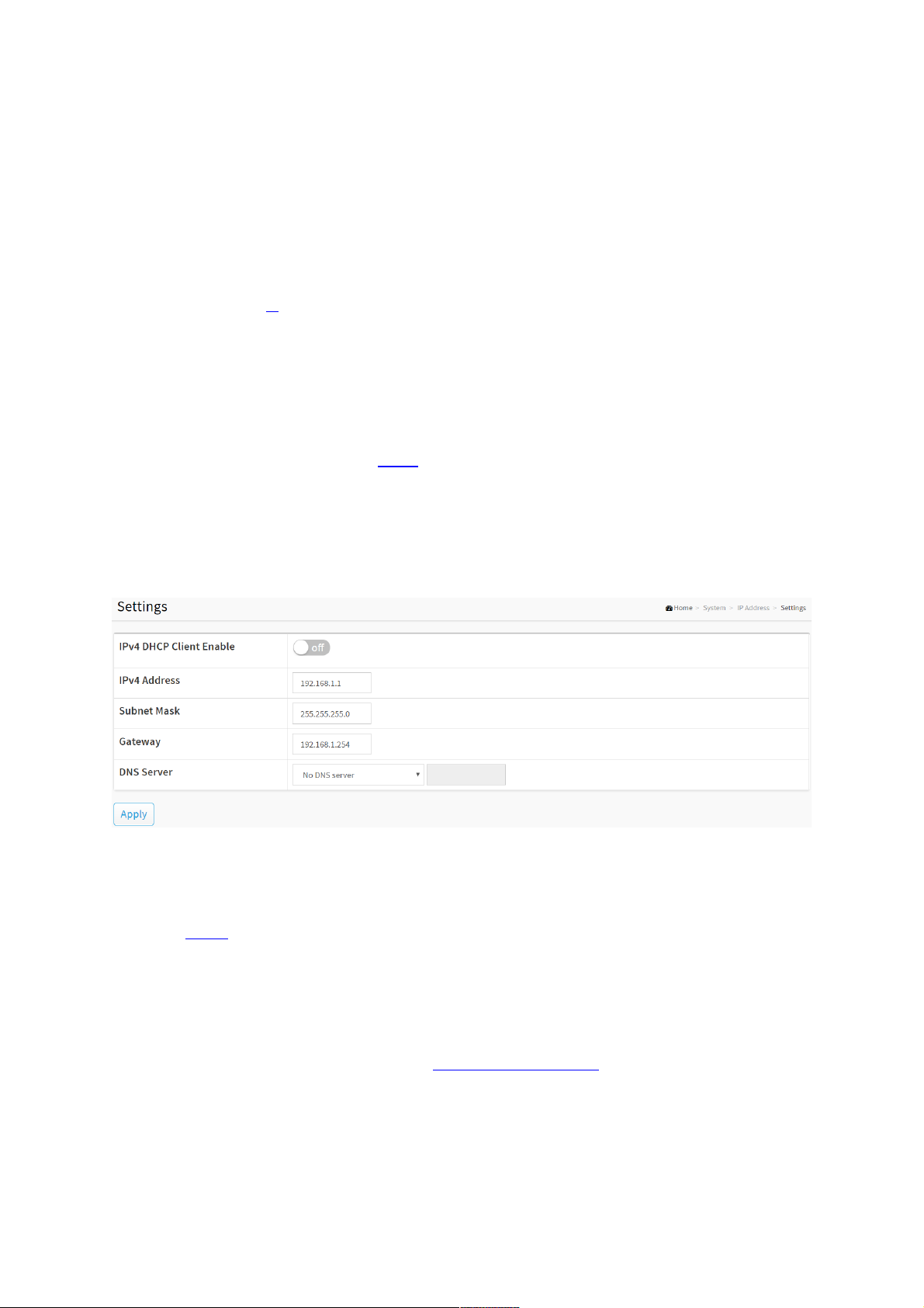
2-2.1 Settings
The IPv4 address for the switch could be obtained via DHCP Server for VLAN 1. To manually
configure an address, you need to change the switch's default settings to values that are
compatible with your network. You may also need to establish a default gateway between the
switch and management stations that exist on another network segment.
Configure the IP basic settings, control IP interfaces and IP routes.
Web Interface
To configure an IP Settings in the web interface:
1. Click System, IP Address and Settings.
2. Enable or Disable the IPv4 DHCP Client.
3. Specify the IPv4 Address, Subnet Mask, Gateway.
4. Select DNS Server.
5. Click Apply
Figure 2-2.1: The IP settings
Parameter description:
IPv4 DHCP Client Enable :
Enable the DHCP client by checking this box. If this option is enabled, the system will
configure the IPv4 address and mask of the interface using the DHCP protocol. The DHCP
client will announce the configured System Name as hostname to provide DNS lookup.
IPv4 Address :
The IPv4 address of the interface in dotted decimal notation.
If DHCP is enabled, this field is not used. The field may also be left blank if IPv4 operation
on the interface is not desired.
Subnet Mask :
The IPv4 network mask, in number of bits (prefix length). Valid values are between 0 and 30 bits for a
IPv4 address.
If DHCP is enabled, this field configures the fallback address network mask. The field may be left
blank if IPv4 operation on the interface is not desired - or no DHCP fallback address is desired.

Gateway :
The IP address of the IP gateway. Valid format is dotted decimal notationor a valid IPv6
notation. Gateway and Network must be of the same type.
DNS Server :
This setting controls the DNS name resolution done by the switch.
There are four servers available for configuration, and the index of the server presents the
preference (less index has higher priority) in doing DNS name resolution.
The following modes are supported:
No DNS server
No DNS server will be used.
Configured IPv4
Explicitly provide the valid IPv4 unicast address of the DNS Server in dotted decimal
notation.
Make sure the configured DNS server could be reachable (e.g. via PING) for activating
DNS service.
Configured IPv6
Explicitly provide the valid IPv6 unicast (except linklocal) address of the DNS Server.
Make sure the configured DNS server could be reachable (e.g. via PING6) for activating
DNS service.
From any DHCPv4 interfaces
The first DNS server offered from a DHCPv4 lease to a DHCPv4-enabled interface will be
used.
From this DHCPv4 interface
Specify from which DHCPv4-enabled interface a provided DNS server should be
preferred.
From any DHCPv6 interfaces
The first DNS server offered from a DHCPv6 lease to a DHCPv6-enabled interface will be
used.
From this DHCPv6 interface
Specify from which DHCPv6-enabled interface a provided DNS server should be
preferred.
Buttons
Apply :
Click to save changes.
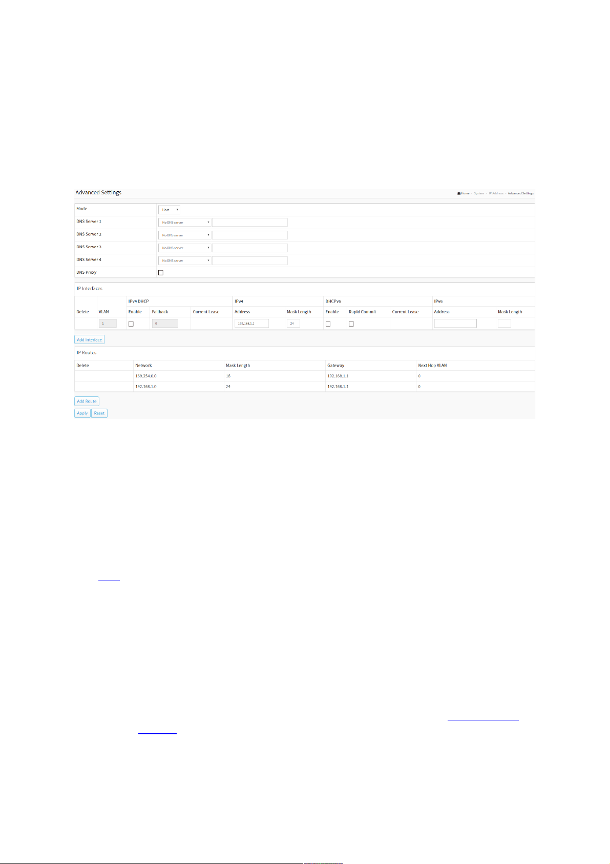
2-2.2 Advanced Settings
Configure the switch-managed IP information on this page
Configure IP basic settings, control IP interfaces and IP routes.
The maximum number of interfaces supported is 128 and the maximum number of routes is
128.
Web Interface
To configure an Advanced Settings in the web interface:
1. Click System, IP Address and Advanced Settings.
2. Click Add Interface then you can create new Interface on the switch.
3. Click Add Route then you can create new Route on the switch.
4. Click Apply.
Figure 2-2.2: The advanced IP settings
Parameter description:
Basic Setting
Mode :
Configure whether the IP stack should act as a Host or a Router. In Host mode, IP traffic
between interfaces will not be routed. In Router mode traffic is routed between all
interfaces.
DNS Server :
This setting controls the DNS name resolution done by the switch.
There are four servers available for configuration, and the index of the server presents the
preference (less index has higher priority) in doing DNS name resolution.
The following modes are supported:
No DNS server
No DNS server will be used.
Configured IPv4
Explicitly provide the valid IPv4 unicast address of the DNS Server in dotted decimal
notation.
Make sure the configured DNS server could be reachable (e.g. via PING) for activating
DNS service.
Configured IPv6
Explicitly provide the valid IPv6 unicast (except linklocal) address of the DNS Server.
Make sure the configured DNS server could be reachable (e.g. via PING6) for activating

DNS service.
From any DHCPv4 interfaces
The first DNS server offered from a DHCPv4 lease to a DHCPv4-enabled interface will be
used.
From this DHCPv4 interface
Specify from which DHCPv4-enabled interface a provided DNS server should be
preferred.
From any DHCPv6 interfaces
The first DNS server offered from a DHCPv6 lease to a DHCPv6-enabled interface will be
used.
From this DHCPv6 interface
Specify from which DHCPv6-enabled interface a provided DNS server should be
preferred.
DNS Proxy :
When DNS proxy is enabled, system will relay DNS requests to the currently configured
DNS server, and reply as a DNS resolver to the client devices on the network.
Only IPv4 DNS proxy is now supported.
IP Interfaces
Delete :
Select this option to delete an existing IP interface.
VLAN :
The VLAN associated with the IP interface. Only ports in this VLAN will be able to access
the IP interface. This field is only available for input when creating an new interface.
IPv4 DHCP Enabled :
Enable the DHCP client by checking this box. If this option is enabled, the system will
configure the IPv4 address and mask of the interface using the DHCP protocol.
IPv4 DHCP Fallback Timeout :
The number of seconds for trying to obtain a DHCP lease. After this period expires, a
configured IPv4 address will be used as IPv4 interface address. A value of zero disables the
fallback mechanism, such that DHCP will keep retrying until a valid lease is obtained. Legal
values are 0 to 4294967295 seconds.
IPv4 DHCP Current Lease :
For DHCP interfaces with an active lease, this column show the current interface address, as
provided by the DHCP server.
IPv4 Address :
The IPv4 address of the interface in dotted decimal notation.
If DHCP is enabled, this field is not used. The field may also be left blank if IPv4 operation
on the interface is not desired.
IPv4 Mask Length :
The IPv4 network mask, in number of bits (prefix length). Valid values are between 0 and
30 bits for a IPv4 address.
If DHCP is enabled, this field is not used. The field may also be left blank if IPv4 operation
on the interface is not desired.
DHCPv6 Enable

Enable the DHCPv6 client by checking this box. If this option is enabled, the system will
configure the IPv6 address of the interface using the DHCPv6 protocol.
DHCPv6 Rapid Commit
Enable the DHCPv6 Rapid-Commit option by checking this box. If this option is enabled,
the DHCPv6 client terminates the waiting process as soon as a Reply message with a Rapid
Commit option is received.
This option is only manageable when DHCPv6 client is enabled.
DHCPv6 Current Lease
For DHCPv6 interface with an active lease, this column shows the interface address
provided by the DHCPv6 server.
IPv6 Address :
The IPv6 address of the interface. A IPv6 address is in 128-bit records represented as eight
fields of up to four hexadecimal digits with a colon separating each field (:). For example,
fe80::215:c5ff:fe03:4dc7. The symbol :: is a special syntax that can be used as a shorthand
way of representing multiple 16-bit groups of contiguous zeros; but it can appear only
once. It can also represent a legally valid IPv4 address. For example, ::192.1.2.34.
The field may be left blank if IPv6 operation on the interface is not desired.
IPv6 Mask Length :
The IPv6 network mask, in number of bits (prefix length). Valid values are between 1 and
128 bits for a IPv6 address.
The field may be left blank if IPv6 operation on the interface is not desired.
IP Routes
Delete :
Select this option to delete an existing IP route.
Network :
The destination IP network or host address of this route. Valid format is dotted decimal
notation or a valid IPv6 notation. A default route can use the value 0.0.0.0 or IPv6 ::
notation.
Mask Length :
The destination IP network or host mask, in number of bits (prefix length). It defines how
much of a network address that must match, in order to qualify for this route. Valid values
are between 0 and 32 bits respectively 128 for IPv6 routes. Only a default route will have a
mask length of 0 (as it will match anything).
Gateway :
The IP address of the IP gateway. Valid format is dotted decimal notation or a valid IPv6
notation. Gateway and Network must be of the same type.
Next Hop VLAN (Only for IPv6) :
The VLAN ID (VID) of the specific IPv6 interface associated with the gateway.
The given VID ranges from 1 to 4094 and will be effective only when the corresponding
IPv6 interface is valid.
If the IPv6 gateway address is link-local, it must specify the next hop VLAN for the gateway.
If the IPv6 gateway address is not link-local, system ignores the next hop VLAN for the
gateway.
Buttons
Add Interface :
Click to add a new IP interface. A maximum of 128 interfaces is supported.
Add Route :
Click to add a new IP route. A maximum of 128 routes is supported.
Apply :
Click to save changes.
Reset :
Click to undo any changes made locally and revert to previously saved values.
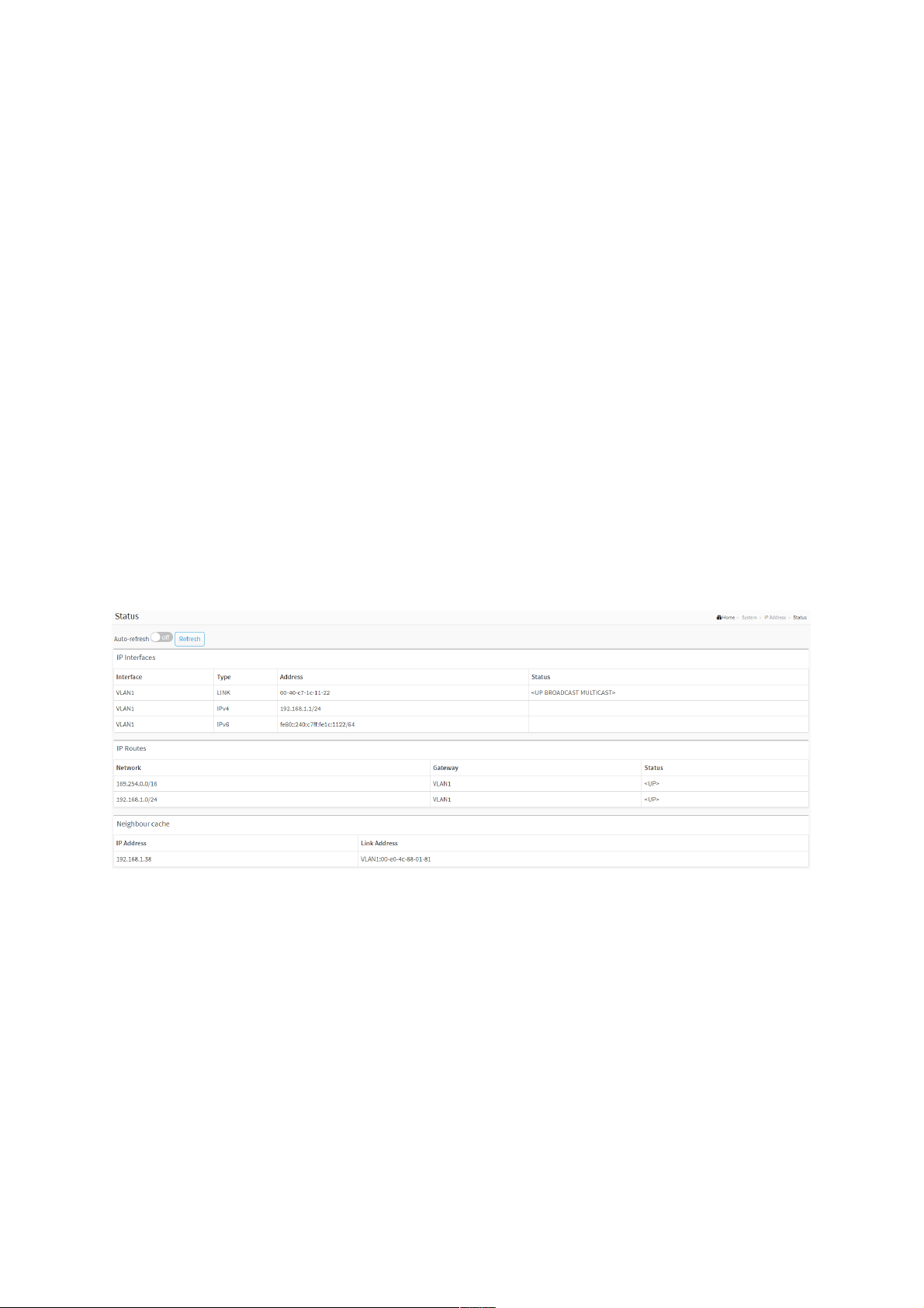
2-2.3 Status
2-2.3.1 IP Status
This page displays the status of the IP protocol layer. The status is defined by the IP
interfaces, the IP routes and the neighbour cache (ARP cache) status.
Web Interface
To display the log configuration in the web interface:
1. Click System, IP Address, Status and IP Status.
2. Display the IP Configuration information.
Figure 2-2.3.1: The IP Status
Parameter description:
IP Interfaces
Interface :
Show the name of the interface.
Type :
Show the address type of the entry. This may be LINK or IPv4.
Address :
Show the current address of the interface (of the given type).
Status :
Show the status flags of the interface (and/or address).

IP Routes
Network :
Show the destination IP network or host address of this route.
Gateway :
Show the gateway address of this route.
Status :
Show the status flags of the route.
Neighbour cache
IP Address :
Show the IP address of the entry.
Link Address :
Show the Link (MAC) address for which a binding to the IP address given exist.
Buttons
Figure 2-2.3.1: The IP Status buttons
Auto-refresh :
Check this box to refresh the page automatically. Automatic refresh occurs every 3 seconds.
Refresh :
Click to refresh the page immediately.
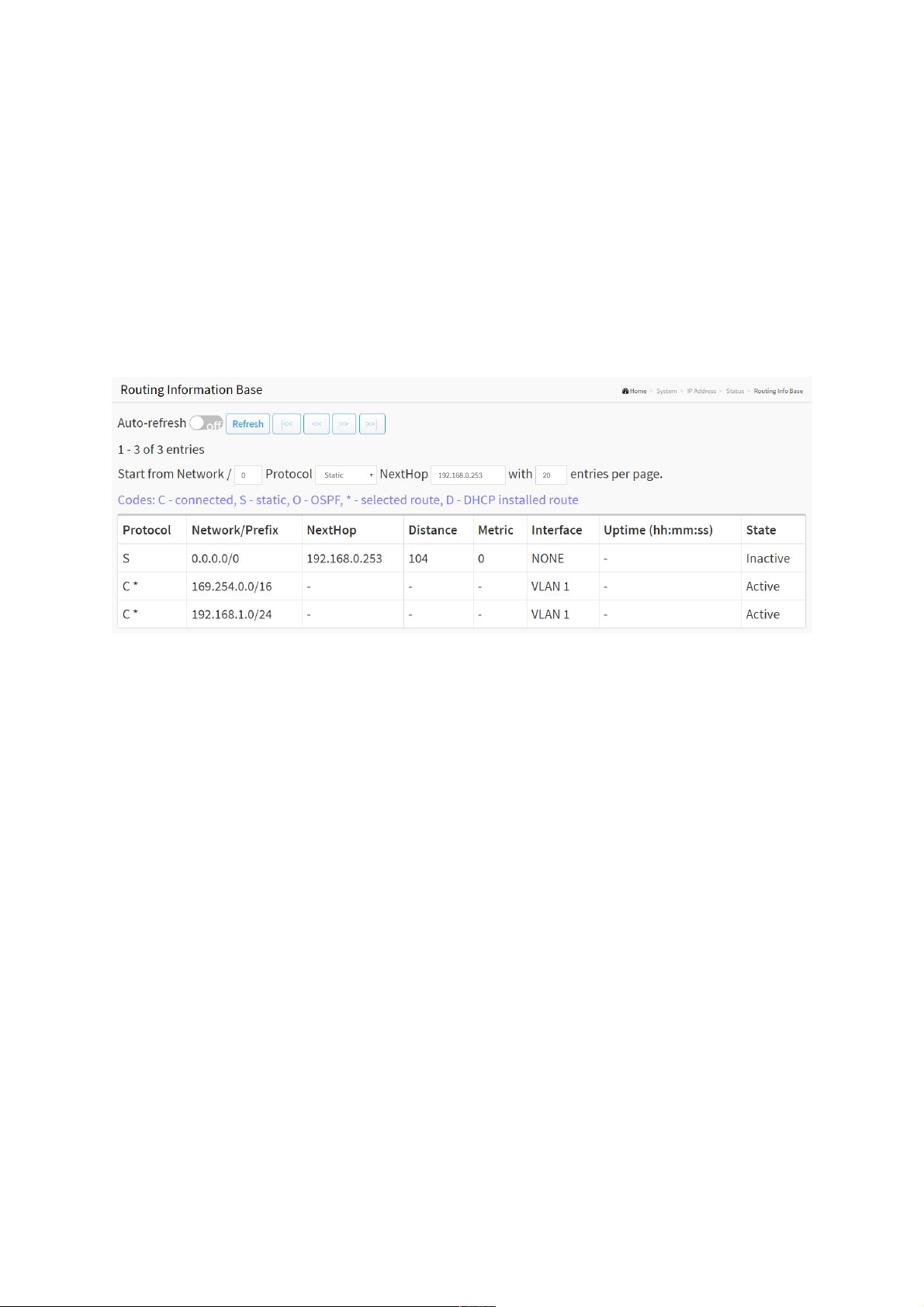
2-2.3.2 Routing Info Base
Each page shows up to 999 table entries, selected through the "entries per page" input field.
When first visited, the web page will show the beginning entries of this table.
Web Interface
To display the log configuration in the web interface:
1. Click System, IP Addres, Status and Routing Info Base.
2. Display the Routing Info Base information.
Figure 2-2.3.2: The Routing Information Base
Parameter description:
Start from ID :
Input field allow the user to change the starting point in this table.
Protocol :
The protocol of the route.
DHCP: The route is created by DHCP.
Connected: The destination network is connected directly.
Static: The route is created by user.
Network/Prefix
Network and prefix (example 10.0.0.0/16) of the given route entry.
NextHop
The IP address of nexthop. Value '0.0.0.0' indicates the link is directly connected.
Distance
The distance of the route.
Metric
The metric of the route.
Interface
The interface where the ip packet is outgoing.
Uptime (hh:ss:mm)

The time till the route is created. The unit is second.
State
Indicate if the destination network is reachable or not.
Buttons
Figure 2-2.3.1: The IP Status buttons
Auto-refresh :
Check this box to refresh the page automatically. Automatic refresh occurs every 3 seconds.
Refresh :
Click to refresh the page immediately.
First Page :
Updates the system log entries, turn to the first page.
Next Page :
Updates the system log entries, turn to the next page.
First Entry :
Updates the table starting from the first entry in the IPMC Profile Address Configuration.
Next Entry :
Updates the table, starting with the entry after the last entry currently displayed.
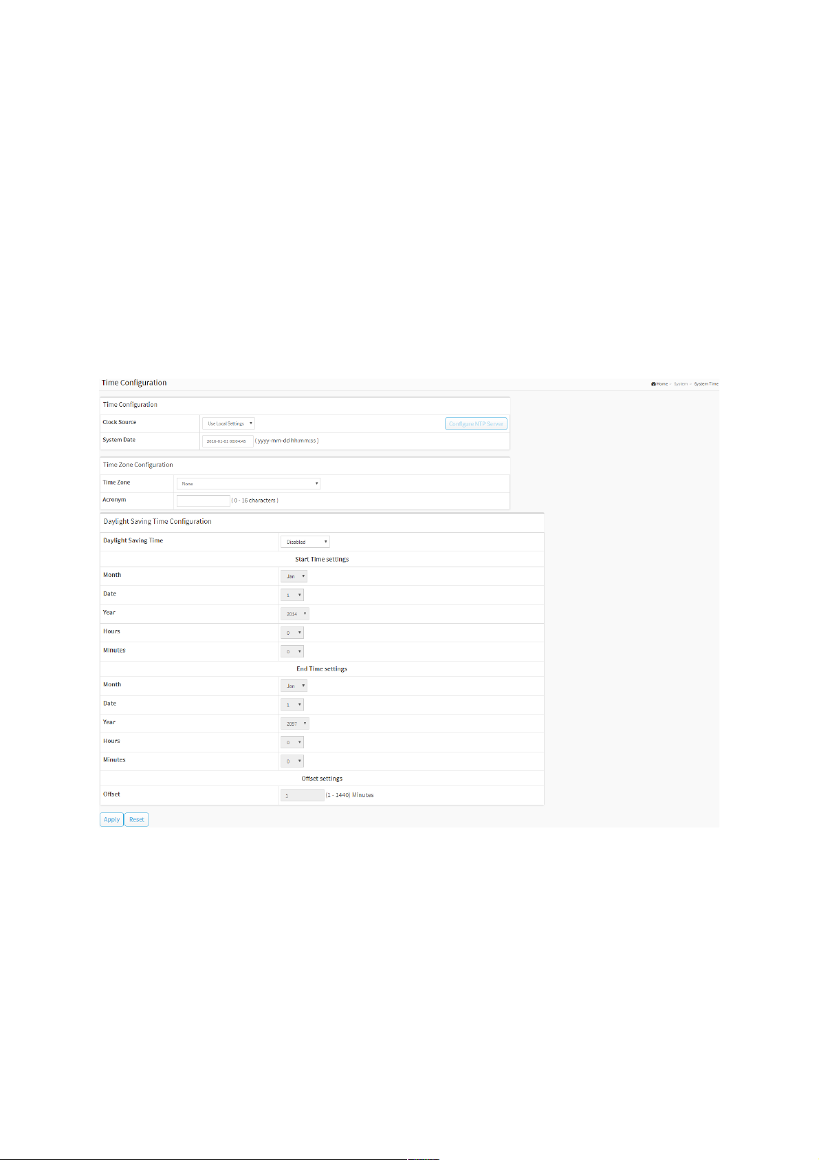
2-3 System Time
The switch provides manual and automatic ways to set the system time via NTP. Manual
setting is simple and you just input “Year”, “Month”, “Day”, “Hour” and “Minute” within the
valid value range indicated in each item.
Web Interface
To configure Time in the web interface:
1. Click System and System Time
2. Specify the Time parameter.
3. Click Apply.
Figure 2-3: The time configuration
Parameter description:
Time Configuration
Clock Source :
There are two modes for configuring how the Clock Source from. Select "Local Settings" :
Clock Source from Local Time. Select "NTP Server" : Clock Source from NTP Server.
System Date :
Show the current time of the system. The year of system date limits between 2011 and
2037.
Time Zone Configuration
Time Zone :

Lists various Time Zones worldwide. Select appropriate Time Zone from the drop down and
click Apply to set.
Acronym :
User can set the acronym of the time zone. This is a User configurable acronym to identify
the time zone. (Range: Up to 16 characters)
Daylight Saving Time Configuration
Daylight Saving Time :
This is used to set the clock forward or backward according to the configurations set below
for a defined Daylight Saving Time duration. Select 'Disable' to disable the Daylight Saving
Time configuration. Select 'Recurring' and configure the Daylight Saving Time duration to
repeat the configuration every year. Select 'Non-Recurring' and configure the Daylight
Saving Time duration for single time configuration. (Default: Disabled).
Start time settings :
Week - Select the starting week number.
Day - Select the starting day.
Month - Select the starting month.
Hours - Select the starting hour.
Minutes - Select the starting minute.
End time settings :
Week - Select the ending week number.
Day - Select the ending day.
Month - Select the ending month.
Hours - Select the ending hour.
Minutes - Select the starting minute.
Offset settings :
Offset - Enter the number of minutes to add during Daylight Saving Time. (Range: 1 to
1440)
NOTE: The under “Start Time Settings” and “End Time Settings” was
displayed what you set on the “Start Time Settings” and “End Time
Settings” field information.
Buttons
Apply :
Click to save changes.
Reset :
Click to undo any changes made locally and revert to previously saved values.
Figure 2-3: The Configure NTP Server button
Configure NTP Server :
Click to configure NTP server, When Clock Source select from NTP Server.

Figure 2-3: The SNTP configuration
NTP is Network Time Protocol and is used to sync the network time based Greenwich Mean
Time (GMT). If use the NTP mode and select a built-in NTP time server or manually specify an
user-defined NTP server as well as Time Zone, the switch will sync the time in a short after
pressing <Apply> button. Though it synchronizes the time automatically, NTP does not
update the time periodically without user’s processing.
Time Zone is an offset time of GMT. You have to select the time zone first and then perform
time sync via NTP because the switch will combine this time zone offset and updated NTP
time to come out the local time, otherwise, you will not able to get the correct time. The
switch supports configurable time zone from –12 to +13 step 1 hour.
Default Time zone: +8 Hrs.
Parameter description :
Server 1 to 5 :
Provide the NTP IPv4 or IPv6 address of this switch. IPv6 address is in 128-bit records
represented as eight fields of up to four hexadecimal digits with a colon separating each
field (:). For example, 'fe80::215:c5ff:fe03:4dc7'. The symbol '::' is a special syntax that can be
used as a shorthand way of representing multiple 16-bit groups of contiguous zeros; but it
can only appear once. It can also represent a legally valid IPv4 address. For example,
'::192.1.2.34'.
Buttons
These buttons are displayed on the SNTP page:
Apply :
Click to save changes.
Reset :
Click to undo any changes made locally and revert to previously saved values.
2-4 LLDP
The switch supports the LLDP. For current information on your switch model, The Link Layer
Discovery Protocol (LLDP) provides a standards-based method for enabling switches to
advertise themselves to adjacent devices and to learn about adjacent LLDP devices . The Link
Layer Discovery Protocol (LLDP) is a vendor-neutral Link Layer protocol in the Internet
Protocol Suite used by network devices for advertising their identity, capabilities, and
neighbors on a IEEE 802 local area network, principally wired Ethernet. The protocol is formally
referred to by the IEEE as Station and Media Access Control Connectivity Discovery specified
in standards document IEEE 802.1AB.
2-4.1 LLDP Configuration
You can per port to do the LLDP configuration and the detail parameters, the settings will take
effect immediately. This page allows the user to inspect and configure the current LLDP port
settings.
Web Interface
To configure LLDP:
1. Click System, LLDP and LLDP configuration.
2. Modify LLDP timing parameters.
3. Set the required mode for transmitting or receiving LLDP messages.
4. Specify the information to include in the TLV field of advertised messages.
5. Click Apply.
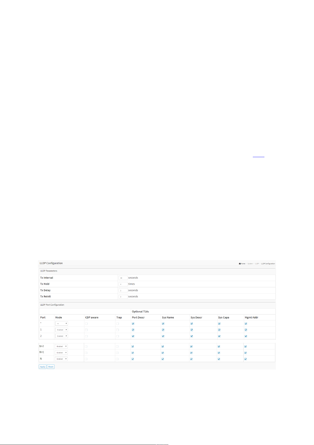
Figure 2-4.1: The LLDP Configuration
Parameter description:
LLDP Parameters
Tx Interval :
The switch periodically transmits LLDP frames to its neighbours for having the network
 Loading...