

Page 1

ROTARY TILLER
ZAPPATRICE
HT2 - HT3 - HT4 - HT6 - HT9
USE AND MAINTENANCE MANUAL
MANUALE DI USO E MANUTENZIONE
EDITION / EDIZIONE 03/2014 CODE / CODICE 070117
Page 2

Page 3

INDEX
0.1 Introduction......................................................................... I
0.2 Staff..................................................................................... V
0.3 Disclaimer............................................................................ VI
1. Identification data....................................................................... 1
1.1 Foreword............................................................................. 1
1.2 Identification data................................................................ 2
1.3 Main parts............................................................................ 2
1.4 Safety devices..................................................................... 5
1.5 Work stations....................................................................... 8
1.6 Noise.................................................................................... 8
1.7 Vibrations............................................................................ 9
2. Safety regulations...................................................................... 11
2.1 General safety regulations................................................... 11
2.2 Regulations for use of the driveline..................................... 13
2.3 Starting regulations............................................................. 16
2.4 Regulations for correct use of the operating machine......... 17
2.5 Regulations for transit on public highways ......................... 22
2.6 Instruction for maintenance technicians.............................. 24
2.7 Prescriptions relating to the hydraulic system..................... 26
2.8 Test regulations................................................................... 27
2.9 Warning and danger plates and stickers............................. 29
3. Testing, delivery of the machine................................................ 35
3.1 Testing................................................................................. 35
3.2 Delivery and handling of the packed machine..................... 35
3.3 Packing size and weight ..................................................... 36
4. Hitching to the tractor................................................................ 39
4.1 Preliminary instructions on use of the machine................... 39
4.2 Coupling the machine to the tractor..................................... 42
4.3 How to shorten the driveline................................................ 45
5. Use of the machine..................................................................... 49
5.1 Instructions on road circulation............................................ 49
5.2 Preparing the implement for work........................................ 50
5.3 Use of the machine.............................................................. 53
5.4 Demounting the implement from the tractor........................ 58
5.5 Working with the rotary tiller (proper use)........................... 59
5.6 Side movement of the rotary tiller....................................... 60
5.7 How to store the machine for long periods......................... 62
Page 4

6. Technical features...................................................................... 63
6.1 Technical data..................................................................... 63
6.2 Weight and overall dimensions........................................... 64
7. Maintenance ............................................................................... 65
7.1 Foreword............................................................................. 65
7.2 Inspections made in our factory.......................................... 67
7.3 Inspections before use........................................................ 68
7.4 Periodical inspections......................................................... 69
7.5 How to carry out the required inspections.......................... 75
7.6 Lubricating and greasing points......................................... 81
7.7 Dismantling......................................................................... 83
7.8 Proper torque for fasteners................................................. 84
8. Troubleshooting......................................................................... 87
8.1 Troubleshooting................................................................... 87
9. Assembly instructions - Kit standing jack.............................. 95
Page 5

INDICE
0.1 Introduzione........................................................................ I
0.2 Personale addetto............................................................... V
0.3 Esclusione di responsabilità................................................ VI
1. Dati anagrafici............................................................................. 1
1.1 Premessa............................................................................ 1
1.2 Dati d'identificazione........................................................... 2
1.3 Parti principali..................................................................... 2
1.4 Dispositivi di sicurezza........................................................ 5
1.5 Posti di lavoro..................................................................... 8
1.6 Rumorosità......................................................................... 8
1.7 Vibrazioni............................................................................ 9
2. Prescrizioni di sicurezza............................................................ 11
2.1 Prescrizioni generali di sicurezza........................................ 11
2.2 Prescrizioni relative all'uso dell'albero cardanico................ 13
2.3 Prescrizioni relative all'avviamento...................................... 16
2.4
operatrice..............................................................................
2.5 Prescrizioni relative al transito su strade pubbliche............ 22
2.6 Prescrizioni rivolte ai manutentori....................................... 24
2.7 Prescrizioni relative all'impianto idraulico........................... 26
2.8 Prescrizioni per le operazioni di collaudo........................... 27
2.9 Targhe ed etichette di avvertenza e di pericolo.................. 29
Prescrizioni relative al corretto uso della macchina
17
3. Collaudo, consegna della macchina......................................... 35
3.1 Collaudo.............................................................................. 35
3.2 Consegna della macchina e movimentazione della
macchina............................................................................. 35
3.3 Dimensione e peso dell’imballo........................................... 36
4. Applicazione al trattore.............................................................. 39
4.1 Prescrizioni preliminari relative all'uso della macchina........ 39
4.2 Aggancio della macchina al trattore..................................... 42
4.3 Come accorciare l'albero cardanico..................................... 45
5. Uso della macchina.................................................................... 49
5.1 Prescrizioni relative alla circolazione stradale..................... 49
5.2 Predisposizione dell'attrezzo al lavoro................................ 50
5.3 Uso della macchina............................................................. 53
5.4 Smontaggio della macchina dal trattore.............................. 58
5.5 Lavoro con la zappatrice (utilizzo consentito)...................... 59
Page 6

5.6 Spostamento laterale della zappatrice................................. 60
5.7 Come immagazzinare la macchina per lunghi periodi.......... 62
6. Caratteristiche tecniche............................................................. 63
6.1 Dati tecnici........................................................................... 63
6.2 Pesi e dimensioni d'ingombro............................................. 64
7. Manutenzione.............................................................................. 65
7.1 Premessa............................................................................ 65
7.2 Controlli effettuati nei nostri stabilimenti.............................. 67
7.3 Controlli da effettuare prima dell'uso................................... 68
7.4 Controlli periodici................................................................. 69
7.5 Come eseguire i controlli richiesti........................................ 75
7.6 Punti di lubrificazione ed ingrassaggio................................ 81
7.7 Messa fuori servizio............................................................. 83
7.8 Coppia adeguata per dispositivi di fissaggio....................... 84
8. Inconvenienti e rimedi................................................................ 90
8.1 Inconvenienti, cause rimedi................................................. 90
9. Schema di montaggio - Piedino di appoggio............................. 95
Page 7

0.1 - Introduction
0.1 - Introduzione
The user of the rotary tiller (also called
"Implement" or "Machine" in the text)
is personally responsible for his own
safety and that of any other people in
the vicinity of the machine.
It is therefore essential for the user
to possess detailed knowledge about
how to use, service and correctly
mount the machine on the tractor.
The figures and descriptions in this
handbook give both users and maintenance staff all the basic instructions to
comply with when using and servicing
the machine.
The user is responsible for ensuring
that connection to the tractor and use
of the machine comply with the current
provisions in merit.
The machine may only be used and
serviced by persons who have become
fully familiar with the contents of this
manual, which should always be kept
ready to hand. Users should become
particularly familiar with chapter 2
concerning safety precautions.
Always comply with the given instructions.
Consult the Hardee After-Sales Service Center or your nearest dealer in
case of doubt.
All’utilizzatore della zappatrice, (più
avanti nel testo chiamata anche "Macchina operatrice" o "Macchina"), è
affidata in prima persona la sicurezza
propria e di eventuali persone nelle
vicinanze.
E’ quindi indispensabile che abbia
conoscenze dettagliate su ciò che
concerne l’uso, la manutenzione ed
il corretto montaggio della macchina
al trattore.
Il presente manuale ha lo scopo di
portare a conoscenza dell’operatore
e degli addetti alla manutenzione, con
figure e testi, le prescrizioni fondamentali ed i criteri da seguire nell’utilizzo e
nella manutenzione della macchina.
E’ responsabilità dell’utente assicurarsi che l’applicazione al trattore e
l’utilizzo della macchina sia conforme
alle disposizioni di legge vigenti.
La macchina deve essere utilizzata e
manutenzionata solo da personale che
abbia letto il presente manuale. Tenerlo
sempre a portata di mano. In particolare leggere il capitolo 2 riguardante
le prescrizioni di sicurezza.
Le istruzioni riportate devono sempre
essere rispettate.
In caso di dubbio consultare il Centro
di Assistenza della ditta Hardee
rivenditore più vicino.
o il
- I -
Page 8

Note
This machine is consigned according
to the warranty conditions valid at the
moment of purchase.
The user must not tamper with the
machine or make modifications to its
parts since such action shall void the
guarantee.
The manufacturer reserves the right
to modify the machine specifications
and performances without advance
warning and declines all responsibility for any errors caused by incorrect
installation or improper use of the
equipment.
Contact Hardee or your nearest
dealer if there are substantial differences between the implement and the
indications in this handbook.
The standards that govern the guarantee are cited in the “Certificate of
Guarantee” which is supplied to the
user with this manual. The section in
this certificate headed “testing and
delivery” must be filled in, leaving no
gaps, and sent to the address printed
on it within 15 days of the delivery
date. If this is not done, the guarantee
is annulled.
Nota
La presente macchina viene consegnata alle condizioni di garanzia valide
al momento dell’ acquisto.
La macchina non deve essere manomessa dall’utente poichè qualsiasi
manomissione o modifica dell’unità
da parte dell’utilizzatore ne invaliderà
la garanzia.
Il costruttore si riserva comunque il
diritto di modificare le specifiche della
macchina ed i criteri di prestazione
senza alcuna notifica declinando ogni
responsabilità per errori derivanti da
una errata installazione o da un utilizzo
improprio.
Nel caso si riscontrassero differenze
sostanziali tra la macchina e quanto
esposto nel presente manuale rivolgersi direttamente alla Hardee o al
rivenditore più vicino.
Le norme che regolano la garanzia
sono citate nel certificato di garanzia
che viene consegnato all'utilizzatore,
accluso a questo manuale.
La sezione "Collaudo e Consegna"
di questo certificato deve essere
compilata in ogni sua parte e spedita
all'indirizzo stampato su di essa, entro
15 giorni dalla data di consegna. In
caso contrario la garanzia è nulla.
Important:
If the “Certificate of Guarantee” has
not been enclosed, ask your nearest
dealer for one, or contact us directly
at:
Hardee by EVH Manufacturing
Co.,
LLC 4895 Red Bluff Road - Loris,
SC 29569 - Phone: 843-756-2555 or
888-990-2555.
Importante:
Se il "Certificato di Garanzia" non
fosse stato consegnato, richiederne
uno al rivenditore più vicino oppure
direttamente a:
Hardee by EVH Manufacturing
LLC 4895 Red Bluff Road - Loris,
SC 29569 - Phone: 843-756-2555 or
888-990-2555.
- II -
Co.,
Page 9
The following symbols are used in the
manual to call the reader’s attention
to various levels of danger.
Di seguito si riportano le simbologie
utilizzate nel presente manuale per
richiamare l’attenzione del lettore sui
diversi livelli di pericolo.
DANGER!!!
Warns of an imminent danger situation
which, if not avoided, will cause death
or serious personal injury.
WARNING!!!
Warns of a potential danger situation
which, if not avoided, could cause
death or serious personal injury, including dangers that occur when the
shields are removed.
CAUTION
Warns of a potential danger situation
which, if not avoided, could cause
slight personal injuries or moderate
wounds.
PERICOLO!!!
Indica una incombente situazione
di pericolo che, se non evitata, provocherà la morte o severe lesioni
personali.
ATTENZIONE!!!
Indica una potenziale situazione di
pericolo che, se non evitata, potrebbe causare la morte o severe lesioni
personali, compresi pericoli che si
presentano quando le protezioni sono
rimosse.
PRUDENZA
Indica una potenziale situazione di
pericolo che, se non evitata, può
provocare lesioni personali minori o
moderate ferite.
IMPORTANT
Symbol used to advise the user about
procedures able to improve use of the
machine and lengthen its life, preventing damage and optimizing the job.
IMPORTANTE
Simbologia usata per consigliare l’operatore sulle procedure per il migliore
utilizzo della macchina per allungarne
la durata, evitarne danneggiamenti ed
ottimizzare il lavoro.
- III -
Page 10

WARNING!!!
ATTENZIONE!!!
For explanatory purposes, some
illustrations in this manual depict
the implement or its parts with
the protective guards or shields
removed.
Never ever use the machine in
the absence of its shields or the
safety protections listed in paragraph 1.4.
WARNING!!!
To prevent serious personal injury
or death:
- avoid dangerous manoeuvres
or maintenance operations;
- never operate or work on the
implement without having read
and become fully familiar with
the contents of this manual;
- if the manual is lost, contact your
nearest dealer or the Hardee
offices for a new copy.
Per motivi di chiarezza, in que-
sto manuale alcune illustrazioni
raffigurano la macchina o parti
di essa con pannelli o carter di
protezione rimossi.
Non utilizzare mai la macchina
se sprovvista di uno o più carter
o delle protezioni di sicurezza
elencate al paragrafo 1.4.
ATTENZIONE!!!
Per prevenire severe lesioni per-
sonali o la morte:
- evitare manovre o interventi di
manutenzione pericolosi.
- Non intervenire od operare sulla
macchina senza aver letto e
compreso questo manuale.
- Se il manuale dovesse essere
smarrito, contattate il Vostro
rivenditore più vicino o direttamente la Hardee per richiederne
uno nuovo.
IMPORTANT
References in this manual to the
right side and left side of the machine mean to the right and left
side of the operator seated in the
tractor’s driving seat.
IMPORTANTE
All’interno del presente manuale
per lato destro e lato sinistro della
macchina si intende il lato destro
e sinistro dell’operatore seduto al
posto di guida del trattore.
- IV -
Page 11

0.2 - Staff
0.2 - Personale addetto
Operator
The machine’s user must be an operator with a suitable technical background to enable him to understand
the contents of this manual, including
the diagrams found herein.
The operator must be familiar with the
main hygiene and accident prevention
regulations, and also the tractor on
which the rotary tiller is mounted.
He must be able carry out the tasks
necessary for the functioning of the unit
comprising the tractor and rotary tiller
together and also the maintenance and
everyday inspections.
The operator must always use the
machine with all the protective guards
in place and in good condition.
Mechanical maintenance staff
This must be a qualified technician
who is capable of working on all the
mechanical parts.
Operatore
L’utilizzatore della macchina deve
essere un operatore del settore con
cultura tecnica sufficiente per capire
il contenuto del manuale istruzioni
compresi gli schemi ed i disegni in
esso contenuti.
Deve conoscere le principali norme
igieniche ed antinfortunistiche, nonchè il trattore sul quale la zappatrice
è montata.
Deve poter svolgere correttamente
le mansioni necessarie al funzionamento dell'insieme trattore-zappatrice.
Esegue interventi ed ispezione giornaliera.
Deve operare rigorosamente con le
protezioni abilitate, correttamente
montate ed in buono stato.
Manutentore meccanico
E' un tecnico qualificato in grado di
intervenire sugli organi meccanici.
- V -
Page 12

0.3 - Disclaimer
0.3 - Esclusione di responsabilità
The rotary tiller has been built in compliance with the accident prevention
regulations in force and therefore the
manufacturer cannot be held responsible for damage resulting from:
- use of the machine with faulty or
missing guards;
- improper use of the machine;
- use of the machine by untrained or
unauthorised personnel;
- incorrect application of the rotary
tiller on the tractor;
- lack of maintenance;
- unauthorised modifications or work
carried out on the machine;
- use of non-original spare parts or
those which are not specific to the
machine;
- failure to observe all or some of
the instructions contained in this
manual;
- exceptional weather conditions.
La zappatrice è stata costruita secondo le norme antinfortunistiche vigenti e
quindi il Costruttore si ritiene sollevato
da ogni responsabilità per:
- uso della macchina con dispositivi
e protezioni mancanti o in avaria;
- uso improprio della macchina;
- uso della macchina da parte di
personale non addestrato o non
autorizzato;
- non corretta applicazione della zappatrice al trattore;
- carenza di manutenzione;
- modifiche o inter venti sulla macchina
non autorizzati;
- utilizzo di ricambi non originali o non
specifici per il modello;
- inosservanza totale o parziale delle
istruzioni contenute nel presente
manuale;
- eventi ambientali eccezionali.
- VI -
Page 13

Identification data
1
Dati anagrafici
1.1 - Foreword
An exact description of the “machine
model” and its “serial number” will en-
sure quick and pertinent answers from
our Technical Assistance Service.
Always exactly state the machine
model in your possession together with
its serial number when contacting our
offices or your nearest dealer.
We suggest you write the data pertaining to your machine in the following
space.
Year of manufacture................
Model......................................
Serial number..........................
Date of purchase.....................
1.1 - Premessa
Una esatta descrizione del “modello
della macchina” e del “numero di
matricola” faciliterà risposte rapide e
pertinenti, da par te del nostro Servizio
di Assistenza Tecnica.
Ogni volta che contattate i nostri uffici
o il Vostro rivenditore più vicino, comunicate sempre esattamente il modello
della macchina e il suo numero di
matricola.
Come promemoria suggeriamo di
riportare i dati della Vs. macchina nel
seguente riquadro.
Anno di costruzione................
Modello...................................
Matricola numero....................
Data di acquisto......................
- 1 -
Page 14
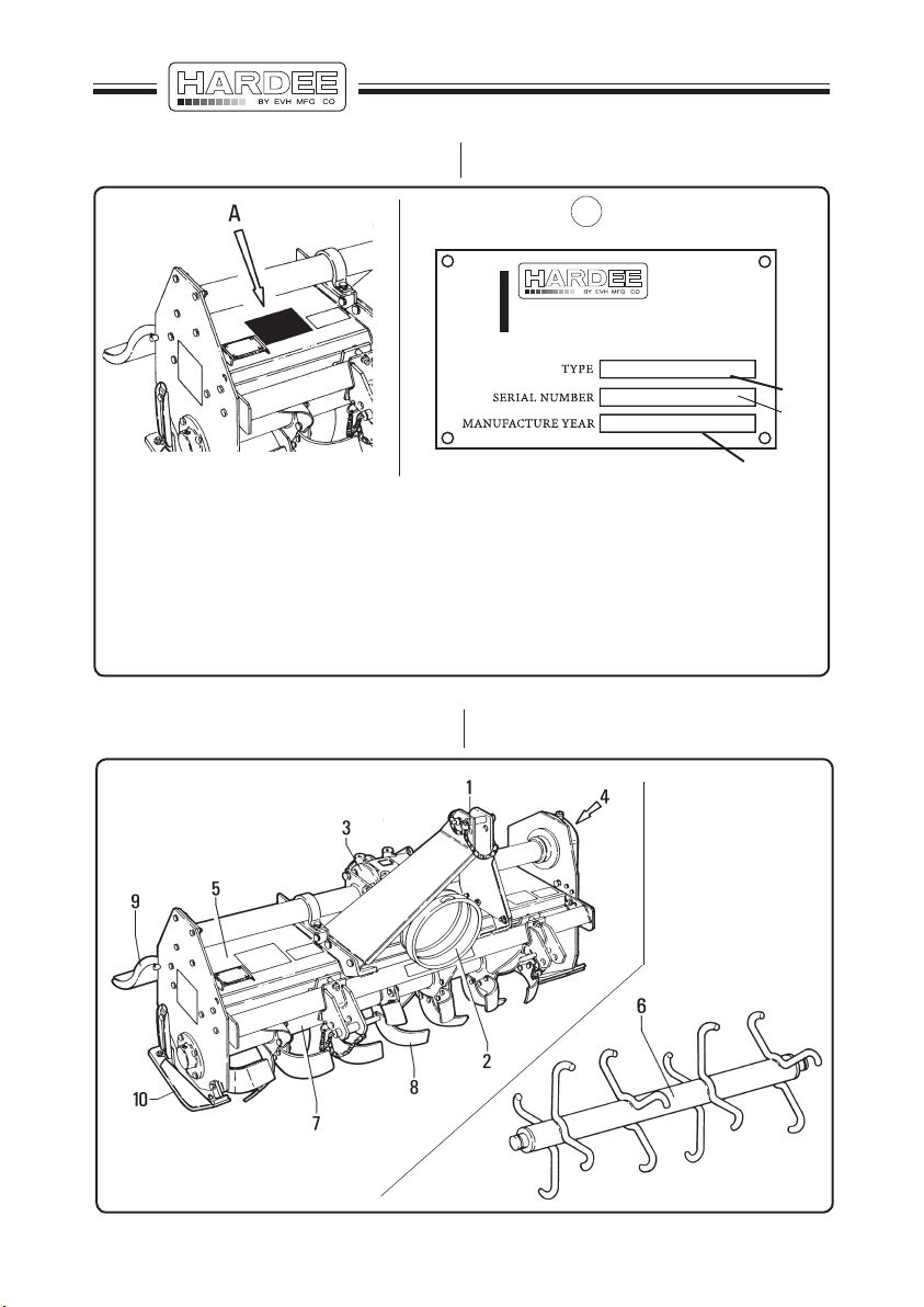
1.2 - Identification data
1.2 - Dati d’identificazione
A
BY EVH MANUFACTURING CO. LLC
4895 RED BLUFF ROAD
LORIS, SC 29569 PHONE: 843-756-2555 OR 888-990-2555
1
2
Z02
1 - Type or model
2 - Serial number
2 - Manufacture year
The data plate indications must
not be altered for any reason
whatsoever
1.3 - Main parts (fig. 1.3.1)
3
1 - Tipo o modello
2 - Numero di matricola
3 - Anno di costruzione
Per nessuna ragione i dati esistenti
sulla targhetta debbono essere
alterati
fig. 1.2.1
1.3 - Parti principali (fig. 1.3.1)
ZA01
Z04
fig. 1.3.1
- 2 -
Page 15

Key to the main parts in fig. 1.3.1
Legenda parti principali fig. 1.3.1
1- Three-point linkage used to couple
the implement to the tractor.
2- Pto shaft guard.
Prevents the user from coming into
contact with the rotating part of the
driveline engaged in the pto.
3- Gearbox.
Reduces the rotation speed of the
tractor pto.
4- Drive transmission to the rotor
shaft.
Drive output from the gear box is
transferred to rotor “7” by means
of the transmission chain.
5- Chassis.
This is the bearing structure of the
implement.
6- Levelling roller (optional).
Adjusts the work depth of the
tools.
As an alternative, some versions
can be equipped with rear wheels
that act in the same way as the
levelling roller.
In alternative, the rotary tillers can
be equipped with side skids "10".
Besides adjusting the work depth
(as the levelling roller), these also
act as a side protection.
1- Attacco a tre punti di aggancio della
macchina al trattore.
2- Protezione albero presa di forza.
Impedisce il contatto da parte
dell’operatore con la parte rotante
dell’albero cardanico inserito nella
presa di forza.
3- Gruppo riduttore.
Riduce la velocità di rotazione
della presa di forza del trattore
(P.T.O.).
4- Trasmissione del moto al rullo
rotore.
Mediante la catena di trasmissione
il moto in uscita dalla scatola ingranaggi viene trasferito al rotore
“7”.
5- Telaio.
E’ la struttura portante della mac-
china.
6- Rullo livellatore (optional).
Regola la profondità di lavoro degli
utensili.
Alcune versioni possono essere
dotate, in alternativa, di ruote posteriori aventi la stessa funzione
del rullo livellatore.
In alternativa le zappatrici sono
equipaggiate con slitte laterali "10"
la cui funzione oltre quella di regolare la profondità di lavoro (come
il rullo livellatore) è di protezione
laterale.
- 3 -
Page 16

7- Rotor shaft.
The tractor drives the rotor shaft on
which the tools are bolted by means
of the gear box and transmission
chain.
8- Blades.
Soil crushing hoe blades are
bolted to the flanges of the rotor
shaft. They can be of various type
according to the machine version
and model.
9- Rear hood (fig. 1.4.1).
The hood is mobile and is used to
contain and level the soil crushed
by the blades.
7- Albero rotore.
Attraverso il riduttore e la catena di
trasmissione, dal trattore giunge il
moto all’albero rotore al quale sono
imbullonati gli utensili.
8- Utensili di taglio.
Vi sono zappette imbullonate alle
flange dell'albero rotore che frantumano il terreno. Esse possono
essere di vari tipi, a seconda del tipo
e della versione della macchina.
9- Cofano di chiusura posteriore (fig.
1.4.1).
Il cofano è mobile e viene utilizzato
per contenere e livellare il terreno
frantumato dagli utensili.
10- Side skids
When installed, these allow the
work depth of the blades to be
adjusted.
They also act as important side
guards.
10- Slitte laterali
Quando installate, consentono
di regolare le profondità di lavoro
delle lame.
Inoltre esercitano una importante
azione di protezione laterale.
- 4 -
Page 17
1.4 - Safety devices
1.4 - Dispositivi di sicurezza
DANGER!!!
In compliance with the current provisions in force, your machine has
been equipped with safety protections to safeguard the operator and
any other people in the vicinity.
Never ever tamper with the safety
devices. Such action could cause
serious injury to the operator and
to others.
Z05
PERICOLO!!!
Sulla macchina in Vostro possesso
sono state installate una serie di
protezioni di sicurezza allo scopo di salvaguardare l’incolumità
dell’operatore o di eventuali passanti, nel rispetto delle normative
vigenti.
Non manomettere in nessun caso
i dispositivi di sicurezza. L’operatore rischia la propria e l’altrui
incolumità.
Z09
7
fig. 1.4.1
- 5 -
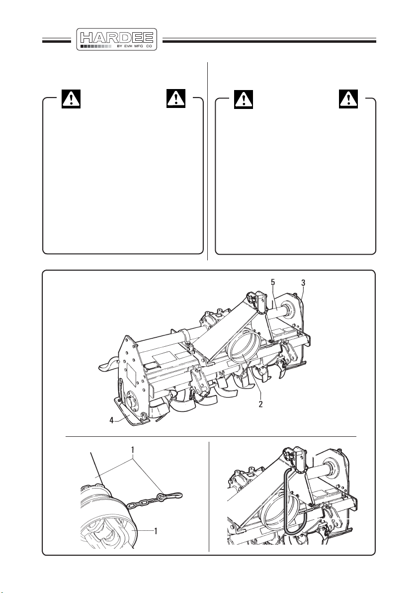
Page 18
- Key to the safety devices (fig.
1.4.1)
- Legenda dispositivi di sicurezza
(fig. 1.4.1)
WARNING!!!
For transport reasons, the acci-
dent-prevention guards are supplied demounted from the machine.
When the machine arrives, the
user shall correctly assemble the
guards, taking care to fully tighten
all fastening elements. It is forbidden to use the machine unless all
the necessary and supplied guards
have been mounted.
1- Driveline shield.
The driveline is supplied with ad-
equate plastic shields and relative
fixing chains.
2- Pto shaft guard.
There is a cowling to protect the
spinning end of the cardan shaft
where this couples to the gearbox
of the machine.
ATTENZIONE!!!
Per esigenze di trasporto le pro-
tezioni antinfortunistiche previste,
vengono fornite smontate dalla
macchina. Al ricevimento della
macchina sarà cura dell’utente procedere al loro corretto montaggio
bloccando con cura ogni elemento
di fissaggio. Si fa divieto dell’uso
della macchina se è priva di una
qualunque delle protezioni previste
e consegnate.
1- Protezione albero cardanico.
L’albero cardanico viene fornito di
adeguate protezioni in plastica e
di catenelle per il fissaggio delle
stesse.
2- Protezione albero presa di forza.
In corrispondenza alla zona di
attacco dell’albero cardanico alla
scatola ingranaggi della macchina
è fissata una cuffia che protegge
l’estremità rotante del cardano
stesso.
3- Drive chain guard.
It prevents the access to the gears
and to the drive chain.
3- Carter di protezione trasmissione
laterale.
Impedisce l’accesso agli ingranag-
gi ed alla catena di trasmissione.
- 6 -
Page 19

4- Side skids.
Prevent material from being thrown
up or a limb from being accidentally
caught under the implement.
4- Slitte laterali.
Impediscono l’eventuale proiezione
di materiale e l’accidentale inserimento di un arto sotto l’attrezzo.
5- Axle shaft guard.
Prevents contact with the moving
shaft.
On some versions, this guard can
be removed while on others it is
fixed to the gearbox.
Note
The following components are only
supplied in the states where it is obligatory to affix and use the CE conformity
mark for industrial products.
6- Barriers.
Safety bars or panels to prevent
users from approaching dangerous
parts of the machine.
The shape and size of these barri-
ers vary according to the machine
model.
5- Protezione semiasse.
Impedisce il contatto con l’albero
in movimento.
Questa protezione, in alcune ver-
sioni è smontabile, in altre è fissata
alla scatola ingranaggi.
Nota
I componenti di seguito elencati vengono forniti solamente negli stati dove
è in vigore l’obbligatorietà dell’apposizione ed utilizzazione del marchio CE
di conformità per prodotti industriali.
6- Protezioni antiavvicinamento.
Barre o paratie di sicurezza tali da
impedire l’avvicinamento alle parti
pericolose della macchina.
La forma e le dimensioni di queste
protezioni varia da modello a modello.
7- Driveline support.
Having detached the driveline
from the tractor, the shaft itself can
be placed on this support to prevent
it from slipping and dropping.
7- Supporto albero cardanico.
Staccato il cardano dal trattore,
per evitare che si sfili o che cada,
questo viene appoggiato al supporto espressamente previsto sulla
macchina.
- 7 -
Page 20

1.5- Work stations
When working with the machine, the
operator must only seat in the driving
seat of the tractor used to tow the
implement.
No one else may approach the machine. Since objects thrown up by the
machine may represent a hazard,
the operator should always keep at a
due distance from persons, built-up
areas, etc.
Leave the driver’s position only after
having:
- disengaged the power takeoff;
- inserted the brake;
- turned off the engine;
- removed the ignition key from the
dashboard.
1.5- Posti di lavoro
Durante le fasi di lavoro con la
macchina, l’operatore deve trovarsi
esclusivamente al posto di guida del
trattore di traino.
Nessun altro deve trovarsi in prossimità
della macchina ma, data la pericolosità
che deriva da eventuali oggetti che
possono venire lanciati, mantenersi
a debita distanza da passanti, aree
abitate ecc...
Allontanarsi dal posto di guida solamente dopo aver:
- disinserito la presa di forza;
- inserito il freno di stazionamento;
- spento il motore;
- tolto la chiave di accensione dal
cruscotto.
1.6- Noise
Measurements of the noise issued by
the machine indicate that the equivalent noise level is such as to maintain
the daily level to which the operators
are exposed within a value of less
than 70 dBA.
This measurement was made with a
sound level meter set at a distance
of about 1.6 m from the machine and
at a height of 2 m, operated (no-load)
at a pto rotation rate of 450 rpm on
grassy land.
Please also note that the machine is
normally used outdoors and that the
position occupied by the operator is
seated in the driving seat of the tractor.
Also consult the prescriptions listed
in the tractor use and maintenance
manual.
1.6- Rumorosità
I rilevamenti del rumore aereo emesso
dalla macchina indicano che il livello
equivalente (dBA) di rumorosità è tale
da mantenere il livello di esposizione
giornaliera sugli operatori a un valore
inferiore a 70 dBA.
Tale rilevamento è stato effettuato con
un fonometro posto a circa 1,6 m di
distanza dalla macchina e a 2 m di
altezza, messa in azione (a vuoto) al
regime di rotazione di 450 giri/min della
presa di forza, su suolo erboso.
Ricordando inoltre che la macchina
normalmente lavora all'aperto e che
la posizione occupata dall'operatore si
trova sul posto di guida del trattore, si
rimanda anche alle prescrizioni riportate sul manuale uso e manutenzione
del trattore.
- 8 -
Page 21

1.7- Vibrations
1.7- Vibrazioni
During normal operation, the machine
will not transmit appreciable vibrations
to the tractor or, thus, to the operator.
These vibrations are less than 2.5 m/
sec2 to the operator’s upper limbs and
less than 0.5 m/sec2 to the seated part
of the operator’s body.
Consult the tractor manual for the
vibrations transmitted by the tractor
itself.
La macchina nel suo normale funzionamento non trasmette vibrazioni
apprezzabili al trattore e quindi all'operatore. Tali vibrazioni sono inferiori ai
2
2,5 m/sec
per le membra superiori
dell'operatore ed inferiori a 0,5 m/
sec2 per la parte seduta del corpo
dell'operatore.
Consultare comunque il manuale del
trattore per le vibrazioni trasmesse dal
trattore stesso.
- 9 -
Page 22

- 10 -
Page 23
2
Safety regulations
Prescrizioni di sicurezza
2.1 - General safety regulations
DANGER!!!
This machine must only be used
for the purpose for which it was
designed and tested. Permitted
use are indicated in paragraph
5.5 (page 59).
Moreover, it must only be used with
a suitable tractor, see par. 4.1 and
driven by an adeguate driveline
driven by the tractor PTO.
All other use is strictly prohib-
ited.
Users should become thoroughly
familiar with the contents of this
manual before using, servicing,
mounting the implement on the
tractor and all other pertinent
operations.
2.1 - Prescrizioni generali di sicurezza
PERICOLO!!!
La presente macchina deve esse-
re utilizzata solamente per i lavori
per cui è stata progettata e collaudata. Verificare l'utilizzo consentito
al par. 5.5. (pag. 59).
Può essere usata solamente con
un idoneo trattore, vedi par. 4.1 e
comandata da un adeguato albero
cardanico che prenda il moto dalla
PTO del trattore.
Ogni altro utilizzo è severamente
proibito.
Leggere attentamente questo
manuale prima di procedere alle
operazioni di montaggio al trattore,
impiego, manutenzione ed ogni
altro intervento sulla macchina.
- 11 -
Page 24

DANGER!!!
PERICOLO!!!
Never wear jewellery, loose cloth-
ing such as ties, scarves, belts, unbuttoned jackets or dungarees with
open zips which could become
caught up in moving parts.
Always wear approved garments
complying with accident prevention provisions such as: nonslip
shoes, ear muffs, goggles and
gauntlets.
Wear a jacket with reflecting
stickers if the implement is used
during the evening near public
highways.
Consult your dealer, the “Labour
Health Service” or your nearest
equivalent authority for information
about the current safety provisions
and specific regulations to comply
with in order to ensure personal
safety.
Non indossare gioielli, capi di
vestiario slacciati o penzolanti
come cravatte, sciarpe, cinture,
giacche sbottonate o tute con
chiusure lampo aperte che possono impigliarsi nelle parti in movimento. Indossare sempre capi
approvati ai fini anti-infortunistici
come: scarpe antiscivolo, cuffie
antirombo, occhiali di sicurezza,
guanti da lavoro.
Se la macchina viene usata di
sera in prossimità di vie di comunicazione, indossare giubbotti
catarifrangenti.
Consultare il Vostro rivenditore o
il “Servizio di Medicina Preventiva
ed Igiene del Lavoro” o un ente
equivalente, a Voi più vicino, circa
le prescrizioni di sicurezza vigenti
ed i dispositivi specifici da adottare
per la sicurezza personale.
- 12 -
Page 25
2.2 - Regulations for use of the
driveline
DANGER!!! PERICOLO!!!
2.2 - Prescrizioni relative all’uso
dell’albero cardanico
The machine may be supplied with
a driveline complete with shields
able to ensure the operator’s safety
(see paragraph “1.4”).
Keep the non-rotation shields ef-
ficient and in a good condition. If
their condition is poor, they should
be changed before the implement
is used.
Unless it is correctly protected,
the driveline could even cause the
user’s death since it can catch on
parts of the body or clothing.
Always check that the shields are
installed and perfectly efficient
before using the machine.
Check that they are well fixed and
correctly inserted into their housings. Check that the retaining chains
are correctly fixed to the tractor or
machine in order to prevent the
shields from turning together with
the driveline.
Check that the driveline is free to
turn within the shield.
La macchina può essere fornita di
un albero cardanico completo delle
protezioni idonee per garantire la
sicurezza dell’operatore (vedi par.
“1.4”).
Mantenere le protezioni non rotanti
efficienti ed in buone condizioni,
diversamente sostituirle prima di
utilizzare la macchina.
L’albero cardanico, se non è pro-
tetto correttamente, può causare
anche la morte dell’utilizzatore in
quanto può agganciare parti del
corpo o del vestiario.
Prima dell’uso della macchina
verificare sempre la presenza e la
perfetta efficenza delle protezioni.
Verificare che siano ben fissate e
correttamente inserite nelle sedi.
Verificare che le catene di ritenuta
siano fissate correttamente al trattore o alla macchina per evitare
che le protezioni possano ruotare
assieme all’albero cardanico.
Verificare che l’albero ruoti liberamente all’interno della protezione.
Take great care to prevent the
shields from being damaged when
the implement is coupled and released from the tractor.
Prestare attenzione a non dan-
neggiare le protezioni durante le
operazioni di aggancio e sgancio
della macchina dal trattore.
- 13 -
Page 26
DANGER!!!
PERICOLO!!!
Keep the grooved parts perfectly
clean and greased so that they
are able to correctly slide.
Besides being described in this
manual, the method by which the
driveline is coupled must also
be checked out with the instructions in the tractor manufacturer’s
manual.
The correct rotation speed of the
tractor pto is indicated on the pto
shaft guards of each machine.
This rate is usually 540 or 1000
rpm. Always comply with the indicated speed.
The following items are applied
to the driveline (if delivered with
the machine):
- a danger sticker on the shaft
guard (fig. 2.2.2);
- a danger sticker on the driveline
which becomes visible if the
shield is damaged or missing
(fig. 2.2.4).
Strictly comply with the instruc-
tions on the sticker.
Mantenere le parti scanalate cor-
rettamente pulite e ingrassate in
modo da assicurarne la perfetta
scorrevolezza.
Le modalità di aggancio dell’albero
cardanico oltre ad essere descritte
nel presente manuale devono
essere verificate con il manuale
del costruttore del trattore.
La corretta velocità di rotazione
della presa di forza del trattore
(P.T.O.) è ripor tata sulle protezioni
dell’albero presa di forza di ogni
macchina.
Solitamente è 540 oppure 1000
giri al minuto. Attenersi alla velocità indicata.
Sull’albero cardanico (nel caso
che la macchina ne sia provvista)
è applicata:
- una etichetta di pericolo sulla
protezione dell’albero (fig.
2.2.1).
- una etichetta di pericolo sull’albero cardanico che compare
nel caso che la protezione sia
danneggiata o mancante (fig.
2.2.3).
Attenersi scupolosamente alle
indicazioni date dalla etichetta.
- 14 -
Page 27

399CEE001
Z11
fig. 2.2.1
39914100
Z12
fig. 2.2.2
399CEE002
Z13
fig. 2.2.3
- 15 -
399143000
Z14
fig. 2.2.4
Page 28
2.3 - Starting regulations
2.3 - Prescrizioni relative all’avviamento
WARNING!!!
Always check that any imminently
dangerous condition has been appropriately eliminated before using
the implement.
Check that all guards and safety
shields are installed, efficient and
correctly mounted in place.
Never allow inadequately trained
personnel to use the implement.
Before starting, always check that
their are no persons, particularly
children and animals, within the
operative range of the implement.
Examine the work area in order to
become familiar with the type of soil
in question.
Check that there are no obstructions
or objects in the area that could be
caught up by the implement and
thrown up at a distance.
Clean all such objects from the
area.
Never work near roads, paths,
housing areas or places potentially
frequented by people, vehicles, animals, etc.
If such action is inevitable, check
that these areas are deserted before beginning work and while on
the job.
ATTENZIONE!!!
Prima di usare la macchina accer-
tarsi che ogni condizione pericolosa
per la sicurezza sia stata oppurtunamente eliminata.
Verificare che tutti i ripari e le pro-
tezioni di sicurezza siano presenti
ed efficienti, correttamente montati
al loro posto.
Non consentire l’uso a personale
non adeguatamente preparato ed
istruito sul corretto utilizzo della
macchina. Prima dell’avviamento,
assicurarsi che l’area operativa sia
libera da persone, in particolare da
bambini ed animali.
Visionare la zona che dovrà es-
sere lavorata al fine di prendere
confidenza col terreno. Accertarsi
che l’area sia priva di ostacoli o
di oggetti che potrebbero essere
raccolti e scagliati a distanza.
Quando presenti, ripulire la zona
da tali oggetti.
Non operare in prossimità di strade,
sentieri, abitazioni o comunque
vicino a luoghi potenzialmente
frequentati da persone, veicoli,
animali, ecc... Se fosse inevitabile, accertarsi che tali luoghi siano
deserti prima di iniziare il lavoro e
mentre si opera.
- 16 -
Page 29
WARNING!!!
ATTENZIONE!!!
Never start the tractor before
being correctly seated in the driving position.
Never start a faulty implement,
even when such a condition is only
suspected. Contact your nearest
dealer and ask for the implement
to be inspected.
2.4 - Regulations for correct use
of the operating machine
DANGER!!!
Never ever use the machine while
under the influence of alcohol or
the effect of medicines such as
tranquillizers, sedatives, stimulants, drugs or any other substance
as could slow or alter the reflexes
or sight.
Never ever work when there are
persons on the implement.
No one must ride on the tractor
apart from the driver unless this
is explicitly allowed by the tractor
manufacturer.
Non avviare il trattore prima di
essersi correttamente seduti al
posto di guida.
Non avviare la macchina ope-
ratrice in avaria, anche se solamente sospetta, ma avvertire il
rivenditore più vicino delle irregolarità riscontrate e richiederne
l’intervento.
2.4 - Prescrizioni relative al corretto
uso della macchina operatrice
PERICOLO!!!
Non utilizzare assolutamente la
macchina in stato di ubriachezza
o sotto effetto di medicinali come
calmanti, sonniferi, eccitanti, droghe o altro che possa rallentare o
alterare i riflessi o la vista.
Non operare mai con persone a
bordo della macchina operatrice.
Sullo stesso trattore non devono
salire altre persone al di fuori
dell’autista a meno che non sia
espressamente previsto dal costruttore del trattore.
- 17 -
Page 30

DANGER!!!
PERICOLO!!!
The tractor must be equipped
with a roll-bar and/or all other
safety devices prescribed by the
current laws in force. To ensure
his personal safety, the operator
must use these devices correctly.
Consult and strictly comply with
the instructions in the tractor use
and maintenance manual.
The operator should never allow
himself to be distracted when
working. He should pay great attention and concentrate on what
he is doing.
Constantly keep the vehicle under
control and always remember how
to quickly stop and switch off both
the tractor and implement.
Il trattore deve essere provvisto
di roll-bar e/o di ogni altro dispositivo di sicurezza prescritto dalle
normative vigenti.
L’operatore, per la sua sicurezza
dovrà utilizzarli correttamente.
Consultare e attenersi a quanto
prescritto sul libretto di uso e
manutenzione del trattore.
Non distrarsi dal lavoro che si sta
eseguendo ma guardare con attenzione e concentrarsi su quanto
si sta facendo.
Mantenere costantemente il con-
trollo del mezzo e avere sempre
presente come arrestare e spegnere velocemente sia il trattore
che la macchina operatrice.
- 18 -
Page 31

DANGER!!! PERICOLO!!!
Always check that children, adults
and animals keep at an adequate
safety distance from the implement
when it is in use.
Take great care when working on
sloping surfaces. It is preferable
to work upwards or downwards
rather than crosswise in order to
avoid the risk of overturning.
Always check and comply with
the tractor manufacturer’s instructions, particularly in relation to the
maximum gradient on which it is
possible to work.
When working on slopes, it is advisable to reduce the work speed,
gradually varying the speed and
direction of the vehicle during
manoeuvres.
Never repeatedly stop and start
the machine.
Never operate on wet, slippery
grass or soil or where the tyre
grip is precarious. If such action
is inevitable, always work at low
speed to ensure the operator’s
safety.
Pay great attention to any obstructions, stones or other objects
which could hit the knives.
The tractor engine must always be
turned off, and the ignition key must
be removed from the dashboard
when intervening on the machine.
For example, when it is necessary
to detach the machine from the
tractor or if grass or other objects
that might have become tangled
up in it must be removed.
Quando la macchina è in movi-
mento assicurarsi che bambini,
adulti ed animali si mantengano
ad adeguata distanza di sicurezza.
Attenzione a quando si opera su
superfici inclinate. Operare pre-
feribilmente dal basso verso l’alto
o dall’alto verso il basso, anzichè
trasversalmente, per evitare rischi
di ribaltamento. Comunque verificare ed uniformarsi alle istruzioni
fornite dal costruttore del trattore in
particolare alla massima pendenza a cui è possibile operare.
E’ buona norma quando si opera su
piani inclinati, ridurre la velocità di
lavoro e nelle manovre variare con
gradualità la velocità e la direzione
del mezzo.
In particolare non arrestarsi o
partire repentinamente.
Non operare su erba o terreno
bagnato, sdrucciolevole e comunque dove l’aderenza sia precaria.
Se proprio inevitabile, operare a
bassa velocità per garantire la
sicurezza dell’operatore.
Prestare molta attenzione ad oggetti, sassi o altro che potrebbero
colpire le lame.
Spegnere sempre il motore del
trattore e togliere la chiave di
accensione dal cruscotto quando
occorre intervenire sulla macchina ad esempio per staccarla
dal trattore o per togliere erba o
altri oggetti che possono essersi
aggrovigliati alla macchina.
- 19 -
Page 32

DANGER!!! PERICOLO!!!
Before dismounting from the trac-
tor, always disengage the power
takeoff (P.T.O.), turn off the engine,
remove the ignition key from the
dashboard, insert the brake, and
do not approach the machine
before the tools have come to a
complete stop.
After having hit an obstacle, si-
multaneously stop the tractor and
machine tool, turn off the engine,
remove the ignition key from the
dashboard, insert the brake, and
check for any possible damage. If
the machine has been damaged, all
repairs must be carried out before
continuing the working process. Always carry out any required repairs
before continuing work.
When the knives are turning,
always keep the limbs well away
from moving parts and those which
heat during work, such as the
gearbox and the gear case.
Never ever attempt to check or
adjust the chain tension while the
implement is operating. Always
stop it before this operation.
Never ever lubricate the machine
while it is operating, or when the
pto is engaged.
Never smoke while refuelling.
Never refuel near smolder-
ing, sparking material or open
flames.
Prima di scendere dal trattore
disinnestare la presa di forza
(P.T.O.), spegnere il motore, togliere la chiave di accensione dal
cruscotto, inserire il freno di stazionamento e non avvicinarsi alla
macchina prima che gli utensili si
siano fermati completamente.
Dopo un urto contro un ostacolo,
fermarsi, arrestare l’insieme trattore e macchina, spegnere il motore,
togliere la chiave di accensione dal
cruscotto, inserire il freno di stazionamento e constatare l’entità di
eventuali danni. In caso di danni,
prima di continuare, procedere alle
riparazioni del caso.
Con le lame in rotazione, tenere
sempre gli arti lontano dalle parti
in movimento e dalle parti che
durante il lavoro si riscaldano,
come la scatola ingranaggi e la
cassa ingranaggi.
Non tentare mai di verificare o re-
golare la tensione della catena con
la macchina operatrice in funzione,
ma arrestarla prima di tale operazione. Non lubrificare la macchina
quando è in funzione oppure è
inserita la presa di forza.
Non fumare durante il rifornimento
di carburante.
Non fare rifornimento in presenza
di materiale fumante, scintillante
e fiamme libere.
- 20 -
Page 33

WARNING!!!
ATTENZIONE!!!
Always check whether the soil
around the tractor is slippery.
Clean all mud from the soles of
the shoes before mounting the
tractor.
Keep the steps, bearing surfaces,
handrails, shackles and tractor
pedals (brake, clutch and acelerator) clean and free from all foreign
bodies such as oil, grease, mud or
snow in order to prevent all possibility of slipping or tripping.
Keep the operator support areas
on the tractor free from mud or any
thing else that could cause the operator to slip when the implement
is mounted or demounted from
the tractor.
Never jump on or off the tractor.
Always keep both hands and one
foot well anchored.
Never use the control levers or hose pipes as holds.
These are mobile parts and do not
offer a safe grip.
Involuntary activation of a control
could also cause the tractor or implement to accidentally move.
Before the machine is released from
the tractor, it should be rested on the
ground in a stable position using the
support foot where installed.
Always check that the machine is
balanced and stable, then release
if from the tractor, checking again to
ensure that it is firmly positioned.
Fare attenzione alle condizioni di
scivolosità del terreno attorno al
trattore. Prima di salire sulla macchina pulire le suole delle scarpe
da eventuale fango.
Mantenere i gradini, i piani di appoggio, i mancorrenti, i maniglioni di
presa ed i pedali del trattore (freno,
frizione e acceleratore) sempre
puliti e liberi da qualsiasi oggetto
estraneo come olio, grasso, fango
o neve per eliminare ogni possibilità
di scivolare o inciampare.
Mantenere sul trattore i punti di
appoggio per l’operatore liberi da
fango o quanto altro possa causare
lo scivolamento durante le manovre
di montaggio e smontaggio della
macchina dal trattore.
Non scendere o salire sul trattore
con un balzo, ma tenere sempre
entrambe le mani ed un piede ben
ancorati.
Non servirsi delle leve dei comandi
o tubi flessibili come appigli poichè sono elementi mobili che non
offrono un appiglio sicuro. Inoltre
un movimento involontario di un
comando può provocare il movimento accidentale del trattore o
della macchina operatrice. Prima di
sganciare la macchina dal trattore
appoggiarla a terra e stabilizzarla
con apposito piede, dove presente,
o comunque accertarsi che sia in
equilibrio stabile, quindi sganciare
la macchina dal trattore e verificare
la sua reale stabilità.
- 21 -
Page 34

2.5 - Regulations for transit on
public highways
2.5 - Prescrizioni relative al transito
su strade pubbliche
WARNING!!!
When driving on public roads,
always comply with the highway
code provisions in force in the
country where the machine is
being used.
Pay particular attention near
crossroads, underpasses, level
crossings, when meeting other
vehicles, overtaking stationary or
slower vehicles, etc...
Drive near the edge of the road
and try not to hold up the traffic.
Never park the tractor and/or the
operating machine near crossroads, bends, level crossings or
where the equipment could be a
danger or obstruction to pedestrian traffic.
ATTENZIONE!!!
Percorrendo strade pubbliche,
attenersi alle disposizioni inerenti
la circolazione stradale dello Stato
in cui la macchina si trova; obbedire a tutte le norme del codice
della strada e ricordarsi le norme
della buona condotta stradale. In
particolare usare la dovuta attenzione in prossimità degli incroci
dei sottopassaggi, dei passaggi
a livello, incrociando altri veicoli,
nel sorpasso di veicoli fermi o più
lenti, ecc...
Viaggiare in prossimità del ciglio
stradale cercando di non intralciare il traffico.
Non posteggiare il trattore e/o la
macchina operatrice in prossimità di incroci, di curve, passaggi
a livello e in genere ove possa
essere di intralcio o di pericolo al
pubblico passaggio.
- 22 -
Page 35

WARNING!!!
ATTENZIONE!!!
Before driving on to public high-
ways, always check that the
width of the machine complies
with current provisions governing maximum permitted vehicle
widths.
Some models have accessories
enabling the shredder to be transported longitudinally.
Mount the rear reflecting triangles,
marker lights and the hazard
flashers.
Always check local laws and
regulations governing transit on
public highways.
Never drive on public highways
when the implement or tractor are
particularly dirty since soil, grass
and other items could drop on to
the road and obstruct the normal
road traffic.
Prima di immettersi su strade
pubbliche, verificare che la larghezza della macchina rientri
nelle normative vigenti relative al
massimo ingombro trasversale
consentito. Alcuni modelli sono
già accessoriati per la presa e il
trasporto longitudinale. Montare
i triangoli posteriori catarifrangenti, le luci di segnalazione
degli ingombri, il lampeggiante e
comunque accertarsi delle leggi
e regolamentazioni vigenti localmente per il transito su strade
pubbliche.
Evitare di immettersi su strade
pubbliche con la macchina o il
trattore particolarmente sporchi
che potrebbero lasciare sulla
strada una scia di terriccio, erba
e quant’altro che produca sporcizia e intralcio al normale traffico
stradale.
Disengage the pto and discon-
nect the driveline when transporting the implement.
Durante il trasporto dell’attrez-
zatura disinserire la presa di
forza (P.T.O.) e scollegare l’albero
cardanico.
- 23 -
Page 36

2.6 - Instruction for maintenance
technicians
2.6 - Prescrizioni rivolte ai manutentori
DANGER!!!
The implement must be stationa-
ry and the tractor pto disengaged
before any work is carried out on
the implement.
WARNING!!!
Routine and extraordinary main-
tenance operations must be carried out in a specially prepared
place using correct and efficient
tools.
This place must always be kept
clean and dry.
There must be sufficient space
around the implement to allow
work to be easily carried out.
Only trained and specialized per-
sonnel must be allowed to service
the implement. Contact your nearest dealer when maintenance
work is required.
PERICOLO!!!
Ogni intervento riparativo deve
essere eseguito esclusivamente a
macchina ferma e scollegata dalla
presa di forza del trattore.
ATTENZIONE!!!
Effettuare le operazioni di manu-
tenzione ordinaria e straordinaria
in un luogo opportunamente predisposto con l’idonea attrezzatura
sempre disponibile ed efficiente.
Il luogo deve essere mantenuto
sempre pulito, asciutto e con
sufficiente spazio intorno, per
agevolare le operazioni.
Ogni intervento deve essere ese-
guito da personale specializzato
e preparato.
A tale scopo contattare il rivenditore a Voi più vicino.
Comply with the indicated bans
and procedures when servicing
the implement.
Rispettare i divieti e le procedu-
re date per la manutenzione e
l’assistenza tecnica riportate nel
presente manuale.
- 24 -
Page 37

WARNING!!!
ATTENZIONE!!!
Never ever use gasoline, solvents
or other inflammable fluids as detergents.
Use the non-flammable and nontoxic commercially available solvents authorized by the competent
authorities.
Never use compressed air or highly
pressurized water to clean the implement. When this is absolutely
inevitable, protect the eyes using
goggles with side guards and use
the lowest possible pressure. At the
end of the job, check and inspect
the implement while it is still disconnected from the tractor.
Check the wear of the work tools.
Never carry out welding operations
without the manufacturer’s permission and instructions.
Before welding, always detach the
implement from the tractor in order
to prevent damage to the battery.
Always wear a protective mask,
goggles and gauntlets when welding, lapping or grinding, hammering
or drilling.
Having completed the maintenance
operations, thoroughly inspect the
implement and check that all nuts,
bolts and hydraulic connections (if
any) are well tightened and that all
stops, plugs, split pins and so forth,
are in a good condition.
Non utilizzare mai benzina, solventi
o altri liquidi infiammabili come
detergenti.
Ricorrere invece a solventi commerciali infiammabili e non tossici,
autorizzati dagli enti competenti.
Non utilizzare l’aria compressa o
l’acqua ad alta pressione per la
pulizia della macchina.
Quando è proprio inevitabile, proteggersi con occhiali aventi ripari
laterali e limitare il più possibile la
pressione. A fine lavoro, con macchina scollegata dal trattore, ispezionarla e verificare l’integrità.
Verificare l’usura degli utensili da
lavoro.
Non effettuare saldature senza il
permesso e le istruzioni del costruttore.
Prima di eseguire saldature staccare la macchina dal trattore per non
danneggiare la batteria.
Indossare sempre la maschera di
protezione, occhiali e guanti da
lavoro quando si eseguono operazioni di saldatura, smerigliatura
o molatura e quando si opera con
il martello o il trapano.
Completate le operazioni di manutenzione, ispezionare attentamente
la macchina e verificare la presenza
e il corretto serraggio di tutta la
bulloneria, di tutte le connessioni
idrauliche (se esistenti) e l’integrità
dei fermi, perni, copiglie, ecc...
- 25 -
Page 38

PERICOLO!!! DANGER!!!
Correctly remount all guards and
shields that were removed during the maintenance and repair
operations.
2.7 - Prescriptions relating to the
hydraulic system
Make sure that all fittings and components are installed before completing
the machine when a hydraulic operating system is installed.
If fittings, tubes or parts of the hydraulic system are demounted, make
sure that the oil is not pressurized. Oil
escaping under pressure can cause
serious injuries.
A physician should be immediately
consulted if fluids are accidentally
swallowed or persons are injured
by oil spurting from the hydraulic
system.
Splashes of fluid on the skin should be
immediately dealt with by the medical
service since they can cause series
infections or dermatosis.
A physician should be immediately
consulted in these cases.
Rimontare correttamente le
protezioni smontate durante le
operazioni di manutenzione o
riparazione.
2.7- Prescrizioni relative all’impianto idraulico
Prima di utilizzare la macchina, quando
è installato un sistema idraulico di spostamento verificare il corretto serraggio
di tutti i raccordi e componenti.
Dovendo smontare raccordi, tubi o
particolari dell’impianto idraulico accertarsi che l’olio non sia in pressione;
la fuoriuscita di olio in pressione può
causare gravi lesioni personali.
Se si ingeriscono fluidi o si rimane lesi
da olii fuoriusciti dall’impianto idraulico,
rivolgersi rapidamente ad un presidio
medico.
Un eventuale contatto del fluido con la
pelle deve essere trattato prontamente
da un servizio sanitario, potendo anche
causare serie infezioni o dermatosi.
Pertanto rivolgersi immediatamente
ad un medico.
- 26 -
Page 39

Remember that fluid leaking from a
very small hole may be almost invisible but may have sufficient force to
penetrate under the skin. Always use a
piece of cardboard or a piece of wood
when searching for leaks.
Never search for leaks with the
hands.
Si ricorda che un fluido che trafila da
un foro molto piccolo può risultare
quasi invisibile ma avere la forza sufficiente per penetrare sotto pelle. Nel
ricercare le perdite idrauliche servirsi
sempre di un cartoncino o di un pezzo
di legno.
Non farlo mai con le mani.
2.8 - Test regulations
WARNING!!!
Always operate the implement
outdoors.
If the implement connected to the
tractor must inevitably be started
in a closed room, eg. during tests
after maintenance, always ensure
that there is adequate ventilation
to prevent harmful exhaust gas
from accumulating.
Carry out various manoeuvres
assisted by specialized personnel
in order to simulate the different
work conditions and acquire the
necessary familiarity with the
implement.
2.8- Prescrizioni per le operazioni
di collaudo
ATTENZIONE!!!
Azionare sempre la macchina
operatrice all’aperto.
Quando risultasse inevitabile la
messa in marcia della macchina
collegata al trattore all’interno di
un locale chiuso, ad esempio per
un collaudo dopo la manutenzione,
garantire una adeguata ventilazione per evitare accumuli di gas di
scarico nocivi all’operatore.
Effettuare diverse manovre si-
mulando l’effettivo lavoro, assistiti
da personale specializzato, per
acquisire la necessaria padronanza dei movimenti ed operare
in sicurezza.
- 27 -
Page 40

DANGER!!! PERICOLO!!!
Before starting, always check that
there are no foreign bodies such
as stones, soil or other, clinging
to the rotor.
When the rotor turns, such items
could detach and be violently
thrown at even notable distances.
Always operate within a protective
cage, or at least near a solid wall.
Always check that no one is too
near or in a potentially dangerous
position if the implement is to be
operated raised from the ground,
when testing for example.
Always disengage the pto before
driving the tractor to transport the
implement from one place to the
other.
Prima dell’avviamento, accertarsi
che oggetti estranei quali sassi,
terra o altro non siano attaccati al
rotore. Infatti, durante la rotazione
del rotore, questi oggetti possono staccarsi ed essere lanciati
con violenza anche a notevole
distanza. Operare sempre all’interno di una gabbia di protezione
o almeno in prossimità di una
solida parete.
Se si intende azionare la macchi-
na sollevata da terra, ad esempio
per un collaudo, accertarsi che
nessuno si trovi in posizione troppo
vicina o comunque pericolosa.
Disinnestare sempre la persa di
forza (P.T.O.) prima di mettersi in
marcia con il trattore nei percorsi
di trasferimento.
- 28 -
Page 41

2.9 - Warning and danger plates
and stickers (fig. 2.9.1)
2.9 - Targhe ed etichette di avvertenza e di pericolo (fig. 2.9.1)
DANGER!!!
Comply with the warnings on the
stickers.
Failure to comply with the given
instructions could cause death or
serious personal injury.
Check that the stickers are always
installed and legible.
If this is not the case, contact your
nearest dealer or Hardee in order
to obtain replacements (state the
code number printed on the lefthand side of each sticker when
ordering).
Fig. 2.9.1 show the stickers in
question.
PERICOLO!!!
Rispettare le avvertenze richiama-
te dalle targhe.
L’inosservanza può causare morte
o severe lesioni personali.
Verificare che le targhe siano
sempre presenti e leggibili.
In caso contrario contattare il rivenditore più vicino o la Hardee stessa
per ottenere le targhette mancanti
o illeggibili che sia necessario sostituire (per l'ordinazione utilizzare
il numero di codice scritto a sinistra
di ogni targhetta adesiva).
In fig. 2.9.1 sono evidenziate le targhe esistenti sulla macchina.
- 29 -
Page 42

Z06
fig. 2.9.1
- 30 -
Page 43

1
Z12
399CEE001
Z11
39914100
fig. 2.9.2
- 31 -
Page 44

72.0386.00
2
- 32 -
fig. 2.9.3
Page 45

3
72.0390.00
fig. 2.9.4
- 33 -
Page 46

72.0391.00
5
- 34 -
fig. 2.9.5
Page 47

3
Testing and delivery of the machine
Collaudo e consegna della macchina
3.1 - Testing
All machine are tested in our plants
to ensure that all moving parts and
the hydraulic system (when installed)
operate correctly.
3.2 - Delivery and handling of the
packed machine
All items are thoroughly checked before dispatch or delivery.
When the implement is received, always check that it has not been damaged during transport. Contact your
dealer if such damage is discovered.
The following paragraphs describe
how to proceed with the lifting operations, which depend on the model and
type of packing in question.
Packaging may vary from country to
country according to shipping requirements (fig. 3.2.1).
3.1 - Collaudo
Ogni macchina viene collaudata presso i nostri stabilimenti per verificare il
buon funzionamento di tutti gli organi
in movimento e quando presente,
dell’impianto idraulico installato.
3.2 - Consegna e movimentazione
della macchina
Prima della spedizione o consegna
tutto il materiale viene accuratamente
controllato.
Al ricevimento della macchina,
controllare che la stessa non abbia
subito danni durante il trasporto. In tal
caso rivolgersi al proprio rivenditore.
Di seguito vengono indicate le modalità di sollevamento che dipendono dai
modelli e dai tipi di imballo.
Gli imballi possono variare nazione
per nazione in base alle esigenze di
trasporto (fig. 3.2.1)
- 35 -
Page 48

WARNING!!!
ATTENZIONE!!!
Use a lift truck, a crane or other
equipment with an adequate carrying
capacity to lift the implement, checking
its weight in the table on par. 3.3.
Check that the load is stable and
well positioned on the truck forks or
crane hook.
Keep the load as low as possible when
moving the implement.
This will ensure greater stability and
visibility.
Set the forks to their maximum width
if a lift truck is used.
Sollevare la macchina con un carrello
elevatore, una gru o con una apparecchiatura di idonea portata, verificando
il peso della macchina nella tabella
di par. 3.3.
Controllare la stabilità ed il posizionamento del carico sulle forche nel caso
di carrello elevatore e sul gancio nel
caso della gru.
Tenere il carico più basso possibile
durante gli spostamenti sia per assicurare maggiore stabilità al carico,
sia per garantire maggiore visibilità
all’operatore.
Utilizzando un carrello elevatore allargare al massimo le forche.
Z07
Lift truck forks
Forche carrello elevatore
3.3 - Packing size and weight
With the exception of particular cases,
the machine will be shipped wrapped
in nylon film.
Z19
fig. 3.2.1
3.3 - Dimensione e peso dell’imballo
Salvo particolari casi, l’imballo viene
eseguito avvolgendo un film di nylon
attorno alla macchina.
- 36 -
Page 49

Z08
fig. 3.3.1
Table of weights and dimensions
Model
Modello
HT2
HT3
HT4
HT6
HT9
4215
5018
5834
6435
6640
7445
8150 2180 86 750 30 800 32 970 38 862 395
A (max.)
mm inch
1150
13504553
1580
17806371
1790
19907179
B (max.)
mm inch
550
5502121
670
6702626
720
7202828
Tabella dimensioni e pesi
C (max.)
mm inch
500
5001919
660
6602626
710
7102828
D (max.)
mm inch
750
7503030
890
8903535
920
9203636
Weight-Peso
lbs kg
253
116
275
126
437
200
470
215
600
275
666
305
- 37 -
Page 50

- 38 -
Page 51

Hitching to the tractor
4
Applicazione al trattore
4.1- Preliminary instructions on
use of the machine
DANGER!!!
Check that all the guards and
shields listed in paragraph 1.4 are
installed and efficient.
Always operate on a flat and levelled surface when hitching the implement to the tractor. This will prevent
dangerous movements.
WARNING!!!
Keep the hands and feet well away
from the knives when hitching the
implement to the tractor.
Never allow anyone to stand
between the tractor and the machine.
4.1 - Prescrizioni preliminari relative all'uso della macchina
PERICOLO!!!
Verificare la presenza e l’efficenza
di tutte le protezioni citate al par.
1.4.
Nell’effettuare l’aggancio operare
su di un piano orizzontale e ben
livellato per impedire movimenti
pericolosi dell’attrezzatura.
ATTENZIONE!!!
Durante le operazioni di mon-
taggio della macchina al trattore
tenere mani e piedi lontano dai
coltelli.
Non consentire l’avvicinamento di
persone nello spazio esistente tra
il trattore e la macchina.
- 39 -
Page 52

WARNING!!!
ATTENZIONE!!!
The implement must be used with
a suitable tractor. Pay particular
care when checking the following
conditions:
- stability. The weight and dimensions of the implement must suit
the technical specifications of the
tractor.
An initial indication as to the
most suitable tractors is given
in the “Average power” column
in paragraph 6.1.
- Maximum tractor power rating.
Consult the values in the “Maximum power” column in paragraph
6.1.
- PTO speed. Consult the values
in the “PTO speed” column in
paragraph 6.1 when choosing
the work speed.
The user shall ensure that the
implement is fit for use with the
tractor in his possession.
La macchina operatrice deve es-
sere utilizzata con idoneo trattore.
Prestare particolare attenzione ai
seguenti parametri:
- stabilità. La massa e le dimen-
sioni della macchina devono
essere ammesse dalle specifiche
tecniche del trattore.
Una prima indicazione sui trattori
più idonei può essere rilevata
dalla colonna “Potenza media”
riportata al par. 6.1.
- Potenza massima del trattore.
Per l’individuazione di tale parametro consultare i valori riportati
alla colonna “Potenza massima”
del par. 6.1.
- Velocità della PTO. Per la scelta
della velocità di lavoro consultare
i valori riportati alla colonna “Velocità PTO” par. 6.1.
Sarà comunque dovere dell’uten-
te verificarne la reale idoneità
finale.
- 40 -
Page 53

CAUTION PRUDENZA
Before using the machine, check
the level of the lubricant in the
gearbox and side casing.
Top up with oil of the same type
if necessary.
Also check that the right support
of the rotor roller has been adequately greased. Consult paragraph 7.6 for the required type of
lubricant.
Check that the blades of the rotor
roller and levelling roller are free
from foreign bodies.
Very worn or broken blades must
be replaced.
Check that all warning and danger
stickers are installed and legible.
Replace them if necessary.
Check that the tractor is in a good
condition.
Check the oil levels in the engine,
gearbox and brakes.
Check the cooling water level and
tyre pressure.
Always refer to the instruction
manual supplied with the tractor.
Prima di utilizzare la macchina
verificare il livello del lubrificante
nella scatola ingranaggi e nel
carter laterale, allo scopo di
evitare danni agli ingranaggi. Se
necessario, rabboccare con olio
dello stesso tipo. Verificare anche
l'ingrassaggio del supporto destro
del rullo rotore. Per il tipo di lubrificante vedi par. 7.6.
Verificare che i coltelli del rullo rotore e il rullo livellatore siano liberi
da eventuali oggetti estranei.
I coltelli molto usurati o rotti devono
essere sostituiti.
Verificare la presenza e la leggibilità di tutte le targhe di avvertenza e di pericolo e se occorre
sostituirle.
Controllare il buono stato di funzionamento del trattore verificandone
i livelli degli olii motore, cambio e
freni, dell’acqua di raffreddamento
e verificare la pressione di gonfiaggio delle gomme.
Fare comunque riferimento al manuale operativo del trattore.
- 41 -
Page 54

4.2 - Coupling the machine to the
tractor
4.2 - Aggancio della macchina al
trattore
Z20
fig. 4.2.1
IMPORTANT
Carefully read the instructions in
paragraph 5.6 on rotary tillers with the
side shifting function.
- Reverse the tractor towards the
machine, aligning the tractor lift links
with the two side coupling pins “1”
fig. 4.2.1.
- Turn off the tractor engine, remove
the ignition key from the dashboard
and insert the brake.
- Insert the ends of the lift links into
implement coupling pins “1”.
- Fix them in place by means of the
relative safety pins “2” fig. 4.2.1.
- Fix the upper rod “12” fig. 4.2.2 of
the three-point hitch “11” and adjust
it until the pto of the implement is
parallel to the ground.
IMPORTANTE
Leggere attentamente le operazioni
descritte nel paragrafo 5.6 relative alle
zappatrici provviste di spostamento
laterale.
- Avvicinare in retromarcia il trattore
alla macchina, allineando i bracci del
sollevatore del trattore ai due perni
laterali di attacco “1” fig. 4.2.1.
- Spegnere il motore del trattore,
togliere la chiave di accensione
dal cruscotto e inserire il freno di
stazionamento.
- Inserire gli snodi di estremità dei
bracci del sollevatore, nei perni “1”
di attacco dell’attrezzo.
- Fissarli inserendo le relative copiglie
di sicurezza “2” fig. 4.2.1.
- Fissare il tirante superiore “12” fig.
4.2.2 dell’attacco a tre punti “11”
e regolarlo fino a portare la presa
di forza della macchina operatrice
parallela al terreno.
- 42 -
Page 55

Z21
- Start the tractor engine and lift the
machine from the ground, then turn
off the tractor engine and remove the
ignition key from the dashboard.
- Operate lift link rod “13” to prevent
excessive oscillations to the side.
Oscillation of about 50 mm each side
(2 inches) is recommended.
- Level the machine at the sides by
adjusting the tractor lift links.
The knives must be at the same
distance from the ground on both
sides of the implement.
- Mount the driveline, checking that
it correctly meshes at both ends.
Consult the descriptions on the fol-
lowing pages for greater details.
If a safety system is required, this
must be mounted from the side of
the implement and not from the side
of the tractor.
Z22
fig. 4.2.2
- Avviare il motore del trattore ed azionare il sollevamento della macchina
da terra, quindi spegnere il motore
del trattore e togliere la chiave di
accensione dal cruscotto.
- Agire sulla regolazione “13” dei tiranti dei bracci del sollevatore per evitare eccessive oscillazioni trasversali.
E’ consigliabile una oscillazione di
circa 50 mm per parte (2 inches).
- Livellare lateralmente la macchina
regolando i bracci del sollevatore
del trattore.
Le lame devono essere alla stessa
distanza da terra da entrambi i lati
della macchina.
- Montare l’albero cardanico verificando il corretto innesto sia dal
lato del trattore che dal lato della
macchina.
Per ulteriori dettagli vedere descri-
zioni alle pagine successive.
Se è previsto un sistema di sicurez-
za, questo deve essere montato dal
lato della macchina operatrice e non
dal lato del trattore.
- 43 -
Page 56

- Check that the driveline is the correct
length fig. 4.2.3.
The minimum coupling length
must be no less than 180 mm (6
inches) in each work position.
Driveline travel must still be about
25 mm (1 inch) in the maximum
coupling position. See fig. 4.2.3.
These are the correct regulations
for safe working conditions.
- Verificare la corretta lunghezza del
cardano fig. 4.2.3.
In ogni posizione di lavoro la lun-
ghezza minima di accoppiamento
non deve scendere sotto ai 180 mm
(6 inches).
Mentre nella posizione di massimo
accoppiamento il cardano deve presentare ancora una corsa di circa 25
mm (1 inch) vedi fig. 4.2.3.
Queste sono le giuste regolazioni
per garantire il lavoro in sicurezza.
DANGER!!!
Always couple the two end forks
of the driveline and check that they
are perfectly locked in place.
To achieve this condition, completely insert the pins and safety
bolts “1” fig. 4.2.3 into the relative
grooves in the pto shafts on both
the tractor and machine sides.
An unlocked shaft could slip out of
position, causing notable mechanical damage and serious injury to
anyone near.
PERICOLO!!!
Provvedere sempre all’innesto
delle due forcelle terminali dell’albero cardanico ed assicurarsi del
loro perfetto bloccaggio.
A tale scopo inserire completamente le spine e i bulloni di sicurezza “1” fig. 4.2.3 nelle scanalature
appositamente predisposte sugli
alberi della presa di forza, sia dal
lato del trattore che dal lato della
macchina.
Un albero non bloccato potrebbe
sfilarsi e causare notevoli danni
meccanici e serie lesioni alle
persone.
- 44 -
Page 57

Z23
Z24
fig. 4.2.3
4.3 - How to shorten the driveline
After the machine has been hitched
to the three-point coupling of the tractor, it should be lifted and lowered to
check that the driveline is the correct
length. If the driveline is too short and
tends to slip out of place, it must be
replaced with a longer one.
CAUTION
Contact your nearest dealer or a
specialized retail outlet if the driveline must be replaced with a longer
one, since this must belong to the
same power category and possess
the same characteristics.
An unsuitable driveline could easily break.
4.3 - Come accorciare l’albero car-
danico
Dopo aver attaccato la macchina ai
tre punti del trattore, alzarla e abbassarla per verificare se la lunghezza
del cardano è corretta.
Se risultasse corto, tendendo a sfilarsi,
occorre provvedere alla sua sostituzione con un albero di lunghezza
maggiore.
PRUDENZA
Qualora occorra sostituire il cardano con uno più lungo rivolgersi al
rivenditore più vicino o a un negozio
specializzato per sostituirlo con uno
della stessa classe di potenza e con
le stesse caratteristiche.
Se si usa un cardano inadatto esso
può rompersi con facilità.
- 45 -
Page 58

If the driveline is too long, it should be
shortened in the following way:
- Set the machine at a minimum distance from the tractor, then brake the
tractor and switch the engine off.
- Separate the two halves of the
driveline. Insert the female part into
the tractor pto and the male part into
the machine pto, checking that the
position is correct by means of the
fixing pins.
Se risultasse lungo, occorre procedere
al suo accorciamento operando come
descritto di seguito.
- Posizionare la macchina nella posizione di minima distanza dal trattore,
bloccare e spegnere il trattore.
- Separare le due metà dell’albero
cardanico, inserire la parte femmina
alla presa di forza del trattore e la
parte maschio alla presa di forza
della macchina verificando la corretta posizione mediante le spine
di ancoraggio.
- Near the two halves of the driveline
together, keeping them parallel.
- Using a felt-tip pen, matchmark the
place where the two halves must be
shortened, measuring 25 mm from
the beginning of each half, as shown
in fig. 4.3.1.
- First cut shield “1” fig. 4.3.2 and,
use part “2” as a reference to cut
the splined shaft.
Z25
fig. 4.3.1
- Affiancare le due metà del cardano
mantenendole parallele.
- Con un pennarello segnare dove accorciare i due semialberi, misurando
25 mm dall’inizio di ogni semialbero,
come da fig. 4.3.1.
- Procedere prima al taglio della
protezione “1” fig. 4.3.2 e usare lo
spezzone “2” come riferimento per
il taglio a misura dell’albero scanalato.
- 46 -
Page 59

Z26
- Proceed in the same way for the
second half.
- Trim and chamfer the two cut ends of
the driveline and clean off all swarf
and shavings.
- Grease the two profiles and join the
two halves of the driveline together
again.
- Mount the driveline and check that
its length is correct by lifting and
lowering the machine.
The shaft must not reach the end
of the tube or project from this. It is
particularly essential to comply with
the previously indicated values (25
and 180 mm).
Z27
fig. 4.3.2
- Procedere allo stesso modo anche
sul secondo semialbero.
- Sbavare e smussare le due estremità
tagliate dell’albero cardanico e pulire
dai trucioli o limature.
- Ingrassare i due profili e ricongiungerli ripristinando l’albero cardanico.
- Montarlo e verificare la correttezza
della misura alzando e abbassan-do
la macchina.
L’albero non deve arrivare al fondo
del tubo nè fuoriuscire da questo, in
particolare devono essere rispettati
i valori riportati in precedenza (25 e
180 mm).
WARNING!!!
Consult the driveline manufactur-
er's use and maintenance manual
in case of doubt.
ATTENZIONE!!!
In caso di dubbio consultare il
libretto di uso e manutenzione del
costruttore dell'albero cardanico.
- 47 -
Page 60

IMPORTANT
The driveline may be equipped with
safety systems able to eliminate the
power overload. The machine will
therefore be safeguarded from damage even if it encounters excessive
resistance during work.
The following safety systems can be
mounted:
- torque limiter with shear bolt;
- clutch with friction disks;
- ratchet torque limiter.
The user must keep these systems in
an efficient condition and ensure that
they are always functional.
Consult the driveline use and maintenance manual for instructions on
how to install and service these safety
systems.
Contact the driveline manufacturer or
Hardee if the manual is mislaid.
IMPORTANTE
L’albero cardanico può avere sistemi
di sicurezza tali da limitare il sovraccarico di potenza. In questo modo
la macchina operatrice non viene
danneggiata anche se durante il lavoro incontra improvvisamente una
resistenza eccessiva.
I possibili sistemi di sicurezza installati
sono i seguenti:
- limitatore di coppia a bullone di
tranciamento;
- frizione a dischi d’attrito;
- limitatore di coppia a nottolini.
Questi sistemi devono essere mantenuti efficienti dall’utente così da
assicurarne nel tempo il loro pieno
funzionamento.
Per l’installazione e la manutenzione di
questi organi di sicurezza, consultare
attentamente il libretto di uso e manutenzione dell’albero cardanico.
In caso di smarrimento del libretto,
rivolgersi al costruttore dell’albero cardanico o direttamente alla Hardee.
- 48 -
Page 61

Use of the machine
5
Uso della macchina
5.1 - Instructions on road circulation
WARNING!!!
Check the local highway code regu-
lations before driving the machine
on public highways with the towed
implement.
Check that the reflectors, hazard
flashers and/or slow vehicle and/
or projecting load indicators are
installed, when required, and efficient.
These indicators must be installed
at the rear of the implement.
They must be clearly seen by the
drivers of other vehicles behind.
If the implement must be transported
at night or in other conditions of poor
visibility, it should be equipped with
sidelights of the type approved by the
highway code regulations in force.
During transport, the machine should
be kept completely lifted with the pto
disengaged.
On request, some very wide models
may be equipped with a wheeled
support for road transport in a longitudinal direction.
5.1 - Prescrizioni relative alla circolazione stradale
ATTENZIONE!!!
Prima di immettersi su strade pub-
bliche con la macchina trainata dal
trattore, verificare le normative locali
riguardanti il trasporto stradale.
Verificare la presenza e l’efficienza
dei catarifrangenti quando richiesti,
del lampeggiante e/o del segnale
di veicolo lento e/o di carico sporgente.
Questi indicatori devono trovarsi sul
retro della macchina operatrice in
posizione ben visibile da ogni altro
mezzo che sopraggiunga posteriormente.
Se si intende viaggiare durante le ore
notturne e comunque in condizioni di
scarsa visibilità, dotare l’attrezzatura
di luci di segnalazione e di ingombro approvate dalle norme stradali
vigenti.
Durante le operazioni di trasporto,
mantenere la macchina completamente sollevata, con presa di forza
disinserita.
Alcuni modelli di grande larghezza
possono essere provvisti, a richiesta,
di un carrello tale da consentire il
trasporto stradale nel senso longitudinale.
- 49 -
Page 62

DANGER!!!
PERICOLO!!!
No one must either lean against
or climb on to the machine during
the work or transfer phases.
This is a farm machine. It MUST
NOT be used to transport persons
or property.
5.2 - Preparing the implement for
work
WARNING!!!
Always be careful to check that the
power rating of the tractor used to
tow the implement does not exceed
the maximum power rating for the
model in your possession (consult
table 6.1).
Check that the P.T.O. speed conforms with the speed required by the
machine.
Compare the values given near the
P.T.O. shaft of the machine.
IMPORTANT
Comply with the instructions in
paragraph 5.2 in order to prevent
early faults and damages to the
implement.
Nessuno deve appoggiarsi e/o
salire sulla macchina sia durante
il lavoro che nelle fasi di trasferimento.
Si tratta di una macchina operatrice agricola NON adibita al
trasporto di persone o cose.
5.2 - Predisposizione dell’attrezzo
al lavoro
ATTENZIONE!!!
Verificare sempre attentamente
che la potenza del trattore di
traino non sia superiore alla potenza massima consentita per il
modello in Vostro possesso (vedi
tabella 6.1).
Verificare che la velocità della presa
di forza sia conforme alla velocità
richiesta dalla macchina.
Confrontare i valori riportati in prossimità dell'albero presa di forza della
macchina.
IMPORTANTE
Rispettare le indicazioni del par.
5.2 per non provocare danni e
precoci rotture alla macchina.
- 50 -
Page 63

5.2.1 - Adjusting the work depth
5.2.1- Regolazione della profondità di
lavoro
DANGER!!!
The following procedures must be
carried out after the machine tool has
been disconnected from the tractor.
If interventions must inevitably be
carried out while the machine tool is
still attached to the tractor, proceed
as follows:
- disengage the power takeoff;
- insert the brake;
- turn off the tractor engine;
- remove the ignition key from the
dashboard.
Never near the limbs to the moving knives. Wait until they have
completely stopped.
The work depth is established by regulating skids “1” or the leveling roller if
installed.
- Use bolts “2” to lower the skids (shallower work depth) or to raise them
(deeper work depth).
Fully tighten bolts “2” after having
adjusted the work depth.
PERICOLO!!!
Le operazioni di seguito elencate
vanno eseguite con la macchina
scollegata dal trattore. Nel caso
risultasse inevitabile intervenire sulla
macchina ancora agganciata al trattore, occorre agire come segue:
- disinserire la presa di forza;
- inserire il freno di stazionamento;
- spegnere il motore del trattore;
- togliere la chiave di accensione
dal cruscotto.
Non avvicinare gli arti ai coltelli in
rotazione ma attendere il loro completo arresto.
La profondità di lavoro viene definita
dalla regolazione delle slitte “1” o del rullo
livellatore se installato.
- Agire sulle viti “2” per abbassare le
slitte (minore profondità di lavoro) e
per alzarle (maggiore profondità di
lavoro).
Effettuata la regolazione e stringere
a fondo le viti “2”.
ZA05
ZA04
fig. 5.2.1
- 51 -
Page 64

IMPORTANT
IMPORTANTE
Make the same adjustment on
both sides to obtain the same
work depth.
Make sure that the work depth
does not exceed the length of
the blades when tilling since this
would impair the system.
CAUTION
When lifting the machine from
the soil, check that the driveline
cannot touch any of its parts.
Eseguire la stessa regolazione
da entrambi i lati per ottenere la
stessa profondità di lavoro.
Prestare attenzione durante il lavoro di zappatura che la profondità
di lavoro non superi la lunghezza
delle lame, pregiudicando altrimenti il buon funzionamento del
sistema.
PRUDENZA
Quando si solleva la macchina
dal terreno verificare che l’albero
cardanico non tocchi qualche
elemento della stessa.
- 52 -
Page 65

5.3 - Use of the machine
5.3 - Uso della macchina
DANGER!!!
Before working with the machine,
always check that all the safety
shields listed in paragraph 1.4 are
installed, correctly mounted and
efficient.
Failing this, stop the rotary hoe
and replace or repair the damaged shields.
Never continue work until all the
shields installed by the ma-nufacturer are efficient.
Contact your nearest after-sales
service center if necessary.
Always make sure to check that
there are no adults, children or animals in the vicinity before beginning
work with the machine.
Always check that the work area
is free from any objects that could
be hit or broken and thrown up by
the knives.
Check that no one enters within
the field of action of the machine
and always work at a safe distance
from roads, built-up areas or places
frequented by persons.
PERICOLO!!!
Ogni volta che ci si appresta
all’utilizzo della macchina, prima
di iniziare il lavoro verificare che
tutte le protezioni di sicurezza
riportate al par. 1.4 siano presenti, correttamente montate ed
efficienti. In caso contrario arrestare la macchina e procedere alla
sostituzione o riparazione delle
protezioni danneggiate.
Non riprendere il lavoro prima di
aver reso efficienti tutte le protezioni previste dal costruttore.
Se necessario, chiedere l’intervento del centro di assistenza
più vicino.
Prima di iniziare il lavoro con
la macchina, verificare sempre
attentamente che non vi siano
persone bambini o animali nelle
vicinanze.
Verificare che l’area da lavorare
sia libera da oggetti che possano
essere urtati o spezzati e lanciati
dai coltelli.
Accertarsi che nessuno entri nel
raggio di azione della macchina
ed operare ad una distanza di
sicurezza da strade, caseggiati o
luoghi frequentati da persone.
- 53 -
Page 66

Make the height adjustments described in paragraph 5.2. Check that
all oil supplies are at the correct level
and grease all required points.
Eseguite le regolazioni in altezza descritte al par. 5.2, verificare il corretto
livello di tutti gli olii ed eseguire l’ingrassaggio in ogni punto previsto.
Always become familiar with machine
use before working with the implement.
Make sure that you know how to quickly
stop the work operations.
- Lower the lift until the knives are near
the ground without touching it.
- Engage the pto.
- Completely lower the tractor lift.
IMPORTANT
Do not allow the machine to drop
violently on to the ground.
Lower it slowly to allow the knives
to gradually cut into the soil.
Violently impact would strongly
stress all machine components
and could cause serious damages.
During work, the lift must always
be fully lowered with the draft
control and position devices disengaged so that they are unable
to influence the work depth of the
machine.
This should only be regulated by
means of the devices (roller, etc.)
on the machine itself.
Prima di utilizzare la macchina, familiarizzare con essa, in particolare
verificare le corrette manovre per
arrestare velocemente le operazioni
di lavoro.
- Abbassare il sollevatore fino a che
le lame siano vicine al terreno senza
toccarlo.
- Inserire la presa di forza.
- Abbassare completamente il sollevatore del trattore.
IMPORTANTE
Non far cadere con violenza la
macchina sul terreno, ma scendere lentamente per consentire il
graduale inserimento delle lame
nel terreno.
In caso contrario si provocherebbero forti sollecitazioni su tutti i
componenti della macchina che
potrebbero compromettere seriamente la loro integrità.
Durante il lavoro il sollevatore
deve essere sempre completamente abbassato e con i dispositivi di controllo della posizione
e dello sforzo disinseriti in modo
da non influenzare la profondità
di lavoro della macchina che va
regolata solo mediante i dispositivi (rullo, ecc...) presenti sulla
macchina stessa.
- 54 -
Page 67

- Accelerate the tractor by depressing the accelerator pedal to about
half its travel and then engage the
pto.
Advance with the tractor, setting the
pto to the required rpm rate (usually
540 or 1000 rpm).
The forward speed of the tractor
must be chosen according to the
type of soil and the degree to which
this must be crumbled.
Optimum work speeds will be be-
tween 1,5 and 2,5 km/hour (1 to 2
mph).
The maximum forward speed able
to guarantee satisfactory work is
generally the best.
To identify this optimum speed,
first select the lowest gear and
progressively increase until the
correct speed able to produce the
most satisfactory result has been
identified.
Gear down and do not release
the accelerator if the speed is too
fast.
- Accelerare il trattore a circa metà
corsa del pedale dell’acceleratore ed inserire la presa di forza
(P.T.O.).
Avanzare col trattore, portando la
presa di forza sul numero di giri richiesto dalla macchina (solitamente 540 oppure 1000 giri al minuto).
La velocità di avanzamento del trat-
tore deve essere scelta in funzione
del tipo di terreno e dal grado di
frantumazione desiderata.
Le velocità ottimali di lavoro vanno
scelte tra i 1,5 e i 2,5 km all’ora.
Generalmente la massima velocità
di avanzamento che garantisca un
lavoro soddisfacente è la migliore.
Per la scelta di questa velocità
ottimale inizialmente selezionare
la marcia più bassa e progressivamente scegliere la marcia superiore fino ad individuare la velocità
corretta che produca il lavoro più
soddisfacente.
Quando la velocità risulta ecces-
siva non rilasciare l’acceleratore
riducendo il numero di giri, ma
passare ad una marcia inferiore.
- 55 -
Page 68

IMPORTANT
IMPORTANTE
The slower the machine advances during work, the more
the soil will be crumbled.
Always raise the implement from
the ground during manoeuvres,
round bends and when reversing.
After having worked for a few
meters, stop and check whether
the desired result is being obtained. Make any adjustments
which may be necessary and
then continue with the job. The
worked soil should always be
kept to the driver’s right.
DANGER!!!
Whenever adjustments must be
carried out on the machine tool,
always turn off the tractor, remove
the ignition key from the dashboard, and insert the brake.
Never move the limbs near to the
spinning blades. Wait for them
to stop.
Il grado di frantumazione del terreno sarà tanto maggiore quanto più
lento sarà l'avanzamento durante
il lavoro.
Nelle manovre, in curva e in retromarcia, sollevare sempre l'attrezzo
da terra.
Dopo pochi metri di lavoro, fermarsi
e verificare la correttezza del lavoro
effettuato.
Eseguire le eventuali ulteriori
regolazioni che si rendessero necessarie e ripartire.
Mantenere il terreno lavorato sempre alla destra del guidatore.
PERICOLO!!!
Ogni volta che si intende interveni-
re in regolazioni sull’attrezzo, spegnere il trattore, togliere la chiave
di accensione dal cruscotto e inserire il freno di stazionamento.
Non avvicinare gli arti alle lame in
rotazione, ma attendere l’arresto
delle stesse.
- 56 -
Page 69

CAUTION
PRUDENZA
Do not reverse with the machine
unless this is strictly necessary.
In these cases, disengage the
PTO, lift the implement from the
soil and make sure that the manoeuvre area is clear.
Never lift the implement more
than 250 mm from the ground with
the pto engaged or the driveline
could break and risk injury to the
operator.
The maximum tilt the driveline can
bear with the pto engaged is 20°
(see fig. 5.3.1), a greater inclination may cause strong vibrations
and/or breaks.
Non retrocedere con la macchina,
se non è strettamente necessario.
In questi casi, disinserire la presa
di forza, sollevare la macchina dal
terreno e osservare attentamente
la presenza di eventuali ingombri
posteriori.
Non sollevare la macchina più di
250 mm da terra con la presa di
forza (P.T.O.) inserita, per evitare
la rottura dell’albero cardanico
esponendo a rischio l’incolumità
dell’operatore.
La massima inclinazione che il cardano può sopportare con la presa
di forza (P.T.O.) inserita, è di 20°
(vedi fig. 5.3.1), l'utilizzo ad un'inclinazione maggiore può provocare
forti vibrazioni e/o rotture.
ER17
DANGER!!!
It is strictly forbidden to lean on
and/or climb on to the machine during the work or transport phases.
The machine is an implement.
It is NOT designed to carry persons
or property.
20°
fig. 5.3.1
PERICOLO!!!
E’ severamente vietato appog-
giarsi e/o salire sulla macchina
sia durante il lavoro che nelle fasi
di trasferimento.
La macchina è una macchina operatrice NON adibita al trasporto di
persone o cose.
- 57 -
Page 70

Note
Since the oil heats, the gearbox may
reach a rather high temperature during
work and its outer surface may become
“hot” to touch.
This is normal and will cause no damage. It is, however, important to always
check that the oil is at the correct level
and of the indicated type (consult the
table in paragraph 7.6).
Nota
Durante il lavoro la scatola ingranaggi
può raggiungere, a causa del riscaldamento dell'olio, una temperatura
tale che la superficie esterna può
“scottare” al tatto; questo è normale
e non provoca danni. E' importante
verificare comunque sempre che l'olio
sia al giusto livello e che sia del tipo
indicato (vedere tabella al par. 7.6).
5.4 - Demounting the implement
from the tractor
- Disengage the pto.
Set the implement on a flat sur-
face.
Stop the tractor and engage the
parking brake.
- Rest the machine on the ground.
- Switch off the tractor engine.
- Remove the ignition key from the
dashboard.
- Remove the driveline.
- Detach the implement from the trac-
tor by disconnecting the three-point
hitch.
- Carry out the operations described
in paragraph 4.1 in reverse.
5.4 - Smontaggio della macchina
dal trattore
- Disinserire la presa di forza (P.T.O),
portare la macchina su un piano
livellato orizzontale, arrestare il
trattore e azionare il freno di stazionamento.
- Appoggiare a terra la macchina.
- Spegnere il trattore.
- Togliere la chiave di accensione dal
cruscotto.
- Togliere l’albero cardanico.
- Staccare la macchina dal trattore
scollegando l’attacco a tre punti.
- Eseguire nell’ordine inverso le ope-
razioni descritte al paragrafo 4.1.
- 58 -
Page 71

5.5 - Working with the rotary tiller
(proper use)
5.5 - Lavoro con la zappatrice (utilizzo consentito)
The rotary tiller is used to crumble the
soil and to prepare it:
1) for seeding;
2) in order to bury grassy residuals
in ploughed soil or soil which has
been subjected to a first working
process;
3) on compact soil.
The rotary tiller is not generally suitable for work on stony soil.
A few small stones are usually tolerated and will create no difficulties.
On the other hand, working on excessively stony soils can damage the
knives and the machine itself. Such
use will also void the guarantee.
La zappatrice è utilizzata per sminuzzare il terreno per prepararlo:
1) alla semina;
2) per interrare eventuali residui
erbosi su terreno arato o che comunque abbia subito una primaria
lavorazione;
3) su terreno compatto.
La zappatrice non è in generale adatta
al lavoro in terreni sassosi.
Qualche sasso di piccole dimensioni
viene normalmente tollerato e non
crea problemi alla macchina.
Al contrario lavorare su terreni eccessivamente sassosi danneggia i coltelli
e la macchina stessa. Inoltre un tale
utilizzo fa decadere immediatamente
la garanzia della macchina.
- 59 -
Page 72

5.6 - Side movement of the rotary
tiller
5.6 - Spostamento laterale della
zappatrice
5.6.1 - Rotary hoes with mobile couplings
Make the side movements with the
machine uncoupled from the tractor.
Make sure that the machine is firmly
resting on the ground.
5.6.1- Zappatrice con attacchi mobili
Effettuare gli spostamenti laterali con
macchina scollegata dal trattore.
Assicurarsi che la macchina appoggiata a terra sia stabile.
ZA10
To facilitate the process, certain types
of rotary tiller are equipped with mobile couplings so that it can be shifted
to the right or left of the tractor.
- Slacken off nuts “2” of mobile cou-
pling “1”.
- Move mobile couplings “1” to the
desired position and lock them in
place by fully tightening nuts “2”.
fig. 5.6.1
Per favorire le esigenze di lavoro,
alcuni tipi di zappatrici sono dotate di
attacchi mobili per poterle spostare a
destra o a sinistra del trattore.
- Allentare i dadi “2” dell’attacco
mobile “1”.
- Spostare gli attacchi mobili “1” nel
punto desiderato e bloccarli in tale
posizione avvitando a fondo i dadi
“2”.
- 60 -
Page 73

IMPORTANT
After having moved the mobile
couplings, make sure that the
driveline is not tilted more than
15° (see fig. 5.6.2).
IMPORTANTE
Dopo aver spostato gli attacchi
mobili verificare che l’inclinazione
dell’albero cardanico non sia superiore a 15° (vedi fig. 5.6.2).
ZA11
- 61 -
fig. 5.6.2
Page 74

5.7 - How to store the machine for
long periods
5.7 - Come immagazzinare la macchina per lunghi periodi
Clean all dirt from the implement.
Always remove all dirt clinging to
the levelling roller or between the
knives.
Park the machine on a flat surface,
in a sheltered place inaccessible to
either children or animals.
The implement should be set in a
stable position, where it is unable to
move, drop or overturn, etc.
Check that the implement stands
on a firm floor surface or ground. In
particular, check that the weight of
the machine is not too heavy for the
surface on which it rests (consult the
weight chart on page 37).
WARNING!!!
Never climb or sit on the machine
since this could lead to personal
injury or damage to the machine
itself.
Pulire l’attrezzo da materiale e sporcizia.
In particolare togliere ogni residuo
impigliato nel rullo livellatore o tra le
lame.
Parcheggiare la macchina su una
superficie piana, possibilmente riparata dalle intemperie, in un luogo
non accessibile a bambini o animali,
in posizione stabile per evitarne spostamenti, cadute ribaltamenti ecc..
Assicurarsi della stabilità del terreno o
pavimento sottostante. In particolare,
verificare che il peso della macchina
non ecceda la portata del piano su
cui è appoggiata (vedi tabella dei pesi
pag. 37).
ATTENZIONE!!!
Non salire o sedersi sulla macchi-
na poichè ci si potrebbe infortunare
o si potrebbero provocare danni
alla macchina stessa.
- 62 -
Page 75

6
Technical features
Caratteristiche tecniche
6.1 - Technical data
WORKING WIDTH
Model
Modello
HT2
HT3
HT4
HT6
HT9
4215
5018
5834
6435
6640
7445
8150 2050 81 50 - 55 60 540 197
LARGHEZZA DI
(mm) (inch)
1050
1250
1450
1650
1650
1850
LAVORO
(Med.) (Max.)
42
50
58
64
65
74
15 - 18
18 - 20
35 - 40
35 - 40
40 - 45
45 - 50
6.1 - Dati tecnici
HP RATING
POTENZA (HP)
25
25
40
40
55
55
P.T.O. SPEED
VELOCITA'
P. T. O
R.P.M.
540
540
540
540
540
540
ROTOR SPEED
VELOCITA'
ROTORE
R.P.M.
214
214
201
201
227
227
- 63 -
Page 76

6.2 - Weight and overall dimensions
6.2 - Pesi e dimensioni d'ingombro
Z08
fig. 6.2.1
Model
Modello
HT2
HT3
HT4
HT6
HT9
4215
5018
5834
6435
6640
7445
A (max.)
mm inch
1150
13504553
1580
17806371
1790
19907179
B (max.)
mm inch
550
5502121
670
6702626
720
7202828
C (max.)
mm inch
500
5001919
660
6602626
710
7102828
D (max.)
mm inch
750
7503030
890
8903535
920
9203636
Weight-Peso
lbs kg
253
116
275
126
437
200
470
215
600
275
666
305
8150 2180 86 750 30 800 32 970 38 862 395
- 64 -
Page 77

7
Maintenance
Manutenzione
7.1 Foreword
DANGER!!!
The machine must always be disconnected from the tractor before
any cleaning, lubricating and servicing operations are carried out.
If interventions must inevitably be
carried out while the machine tool is
still attached to the tractor, proceed
as follows:
- disengage the power takeoff;
- insert the brake;
- turn off the tractor engine;
- remove the ignition key from
the dashboard.
Good, regular maintenance and correct use are essential if the machine
is to remain safe and long lasting.
7.1- Premessa
PERICOLO!!!
Ogni operazione di pulizia, lubrificazione e manutenzione dell’attrezzo deve essere eseguita con la
macchina scollegata dal trattore.
Nel caso risultasse inevitabile
intervenire sulla macchina ancora
agganciata al trattore, occorre
agire come segue:
- disinserire la presa di forza;
- inserire il freno di stazionamento;
- spegnere il motore del trattore;
- togliere la chiave di accensione
dal cruscotto.
Premesse essenziali per garantire
rendimento duraturo nel tempo e
sicurezza di funzionamento della
macchina sono una buona e regolare
manutenzione ed un corretto uso.
- 65 -
Page 78

In particular, comply with the instructions given on the stickers affixed to
the machine, as shown below:
In particolare seguire le indicazioni
riportate nella targhetta esistente sulla
macchina e qui riprodotta:
72.0391.00
Only ever use genuine Hardee spare
parts to ensure the steady and reliable
operation of your machine and prevent
the warranty from becoming void.
- 66 -
fig. 7.1.1
Per un funzionamento costante e regolare della macchina in Vostro possesso
e per evitare il decadimento della garanzia, ogni sostituzione di parti deve
essere effettuata esclusivamente con
ricambi originali Hardee.
Page 79

7.2 - Inspections made in our factory
7.2 - Controlli effettuati nei nostri
stabilimenti
Your implement will have been subjected to various tests and trials both
in our factory and on the dealer’s
premises. This procedure ensures that
operation and the necessary adjustments will be correctly carried out.
In particular, the following inspections
are made:
7.2.1 - Preliminary inspections
1- The implement is checked to see
that the serial number and all stickers have been affixed.
2 - Grease each point as described
in paragraph 7.6 and check the
oil levels in the reduction unit and
gear casing.
3- Check for oil leaks.
4- Check to see that all safety devices
are installed and efficient.
5- General inspection during ope-
ration.
Besides the above inspections, your
implement needs to be constantly
checked and inspected according to
the following frequencies.
La macchina da Voi acquistata ha
subito, presso i nostri stabilimenti e
presso il rivenditore, diversi collaudi,
così da verificarne la corretta messa
in esercizio e le necessarie registrazioni.
In particolare i controlli effettuati
sono:
7.2.1 - Controlli preliminari
1 - Controllo presenza di tutte le tar-
ghette e del numero di matricola.
2 - Ingrassaggio di ogni punto come
descritto al par. 7.6 e controllo livelli
olio del gruppo riduttore e della
cassa ingranaggi.
3 - Controllo perdite olio.
4 - Controllo presenza ed efficenza di
tutti i dispositivi di sicurezza.
5 - Controllo generale di funzionamen-
to.
Oltre a quanto già descritto, l’attrezzatura in Vostro possesso necessita di
costanti controlli e verifiche da effettuarsi con le seguenti scadenze.
- 67 -
Page 80

7.3 - Inspections before use
7.3 - Controlli da effettuare prima
dell’uso
DANGER!!!
To carry out the following procedures, it is necessary to first:
- disengage the power takeoff;
- insert the brake;
- turn off the tractor engine;
- remove the ignition key from the
dashboard.
- Inspect the knives to ensure that they
are free from foreign materials.
- Check the implement for wear and
damage.
Particularly check the knives and
the rear roller integrity.
- Check that all nuts and bolts are fully
tightened, with particular reference
to the knife bolts (for the correct
tightening torque, see the relative
table on page 85).
- Check that the oils and greases in
the various points are at the correct
level, as described in paragraph
7.6.
- Despite the previous inspections,
lubricant may have partially spilt
during transport and need topping
up.
- Make sure that all the guards with
which the machine is equipped have
been correctly mounted.
PERICOLO!!!
Per eseguire le operazioni di seguito elencate occorre:
- disinserire la presa di forza;
- inserire il freno di stazionamento;
- spegnere il motore del trattore;
- togliere la chiave di accensione
dal cruscotto.
- Ispezionare le lame per accertarsi
che siano libere da materiale estraneo.
- Verificare l’assenza di usure o danni
alla macchina.
In particolare verificare l’integrità
delle lame e del rullo posteriore.
- Controllare il serraggio di tutta la
bulloneria con particolare riferimento alle viti di fissaggio lame (per il
corretto serraggio vedere tabella
coppie di serraggio a pag. 85).
- Controllare il corretto livello olii e
l’ingrassaggio dei vari punti come
descritto al paragrafo 7.6.
- Nonostante i controlli precedenti durante il trasporto possono avvenire
parziali fuoriuscite di lubrificante da
ripristinare prima dell’uso.
- Verificare la presenza e il corretto
montaggio di tutte le protezioni di
cui la macchina è dotata.
- 68 -
Page 81

7.4 - Periodical inspections
7.4 - Controlli periodici
DANGER!!!
The following procedures must
be carried out after the machine
tool has been disconnected from
the tractor. If interventions must
inevitably be carried out while the
machine tool is still attached to the
tractor, proceed as follows:
- disengage the power takeoff;
- insert the brake;
- turn off the tractor engine;
- remove the ignition key from
the dashboard.
If work is required under the machine, check that this has been
sufficiently raised and safely locked
to prevent all risks of injury to the
operator.
To prevent all risks, the operator
should not merely trust in the hydraulic system of the tractor since
this can be liable to leaks able to
lower the machine even when the
engine is off.
Always block the machine with a
rigid support when work must be
carried out underneath.
PERICOLO!!!
Le operazioni di seguito elencate
vanno eseguite con la macchina
scollegata dal trattore. Nel caso
risultasse inevitabile intervenire
sulla macchina ancora agganciata
al trattore, occorre agire come
segue:
- disinserire la presa di forza;
- inserire il freno di stazionamento;
- spegnere il motore del trattore;
- togliere la chiave di accensione
dal cruscotto.
Se si deve operare sotto alla
macchina accertarsi che sia sufficentemente sollevata e bloccata in
sicurezza per evitare ogni rischio
all’operatore.
Per evitare ogni rischio all’operatore non affidarsi solamente al
sistema idraulico del trattore in
quanto esso può essere soggetto
a perdite tali da far abbassare la
macchina anche a motore spento. Bloccare sempre la macchina
anche con un sostegno rigido
quando si debba operare sotto
di essa.
IMPORTANT
The given frequencies with which the
maintenance operations listed in this
chapter must be carried out are indicative, since they refer to the machine
when used in normal conditions.
- 69 -
IMPORTANTE
La frequenza degli interventi di manutenzione riportati nel presente
capitolo è indicativa poichè è riferita
a normali condizioni di utilizzo della
macchina.
Page 82

These frequencies may be varied
according to the type of work, the
weather conditions, the texture and
dust content of the soil.
A seguito del tipo di lavoro, delle condizioni atmosferiche, della consistenza e polverosità del terreno i tempi di
interventi possono essere variati.
If the machine is used in heavy duty
conditions, the maintenance operations must be carried out more frequently.
Thoroughly clean the lubricators before injecting grease. This will prevent
impurities from penetrating the various components.
Make sure that the oil used to top up
the supply is the same type as that by
the manufacturer.
ATTENTION!!!
Store the lubricant in a sheltered
place, well away from childrens'
reach.
Always read the recommendations given on the lubricant containers.
Prevent the lubricants from being
splashed on the skin. Wash the
effected part with water if this
occurs.
Old lubricants must be handed
over to authorized disposal companies in compliance with the
antipollution provisions locally in
force.
In particolare, se le condizioni di utilizzo sono gravose, la periodicità degli
interventi di manutenzione dovrà
essere più frequente.
Pulire accuratamente gli ingrassatori
prima di iniettare il grasso per impedire alle impurità di entrare all’interno
dell’organo da lubrificare.
Quando si esegue il rabbocco o la
sostituzione dell’olio, assicurarsi che
l’olio impiegato sia dello stesso tipo di
quello impiegato dal costruttore.
ATTENZIONE!!!
Conservare il lubrificante in luogo
riparato e non raggiugibile dai
bambini.
Leggere sempre le avvertenze
riportare sui contenitori dei lubrificanti.
Evitare il contatto dei lubrificanti
con la pelle; in caso contrario lavare con acqua le parti interessate.
I lubrificanti esausti devono essere consegnati agli appositi enti
autorizzati al loro smaltimento, in
accordo con le norme antinquinamento localmente vigenti.
- 70 -
Page 83

Every 8 hours service
Ogni 8 ore di lavoro
ZA20
- Grease the right suppor t “1” fig. 7.4.1
of the rotor or make sure that there
is oil in the right support “2” fig. 7.4.1
(in versions with support in an oil
bath).
ER08
- Make sure that the driveline is in
a perfect condition and grease the
spiders (fig. 7.4.2).
- Check that the bolts “1” that lock the
blades to rotor “2” (fig. 7.4.2) are well
tightened.
ZA21
fig. 7.4.1
- Ingrassare il supporto destro “1” fig.
7.4.1 del rotore oppure verificare la
presenza di olio nel supporto destro
“2” fig. 7.4.1 (nelle versioni con supporto a bagno d’olio).
ZA22
fig. 7.4.2
- Verificare l’integrità dell’albero cardanico ed ingrassare le crociere (fig.
7.4.2).
- Controllare il serraggio dei bulloni
“1” di bloccaggio lame al rotore “2”
(fig. 7.4.2).
- 71 -
Page 84

Every 50 hours service
Ogni 50 ore di lavoro
- Check the knives for wear. Replace
them if necessary, in compliance with
the instructions in paragraph 7.5.4.
- Demount and clean the driveline.
Be sure to remove all foreign bodies
from the sliding parts of the shaft.
Cover the sliding parts with grease
before remounting the driveline (as
indicated in paragraph 7.5.1).
- Check that all nuts and bolts are fully tightened, particularly the bolts of
the gearbox of the machine.
Mark
Incisione
ZA23
- Controllare lo stato di usura dei coltelli. Se necessita sostituirli, operare
come descritto al par. 7.5.4.
- Smontare e pulire l’albero cardanico.
In particolare eliminare ogni traccia
di corpi estranei dalle zone scorrevoli
dell’albero. Prima di rimontare l’albero, ricoprire le parti scorrevoli con
grasso (come riportato al paragrafo
7.5.1).
- Controllare il serraggio della viteria,
in particolare le viti di fissaggio della
scatola ingranaggi.
ZA24
fig. 7.4.3
- Check the level of the lubricant in
the gearbox through the inspection
plug (fig. 7.4.3 pos. 1) and top up to
the mark on the rod if necessary.
Consult paragraph 7.6 for the lubri-
cant specifications.
The oil must reach the lower edge of
the hole of level plug “1” fig. 7.4.4 in
fig. 7.4.4
- Controllare il livello del lubrificante
contenuto nella scatola ingranaggi
dal tappo ispezione (fig. 7.4.3 pos.
1) ed eventualmente ripristinarlo
fino all’incisione presente sull’asta.
Per le caratteristiche dei lubrificanti
vedere par. 7.6.
Nelle versioni sprovviste di asta livello,
l’olio deve essere a filo inferiore del
- 72 -
Page 85

versions without a dipstick.
Top up the level by pouring oil through
plug “2”.
Consult paragraph 7.6 for the oil
specifications.
ZA26
The level must reach beyond the
mark on the dipstick.
Consult paragraph 7.6 for the oil
specifications.
- Check the level of the oil in the side
transmission housing.
Remove level plug “1” fig. 7.4.5 and
check that the oil reaches the lower
edge of the plug housing. If necessary, top up the level through plug
“2”, using oil with the characteristics
specified in paragraph 7.6.
foro del tappo livello “1” fig. 7.4.4.
Ripristinare il livello introducendo l’olio
dal tappo “2”.
Per le caratteristiche dell’olio vedi
paragrafo 7.6.
fig. 7.4.5
Il livello deve essere al di sopra
dell’incisione ricavata sull’asta livello. Per le caratteristiche dell’olio
vedi paragrafo 7.6.
- Controllare il livello dell’olio nel
carter di trasmissione laterale.
Togliere il tappo livello “1” fig. 7.4.5
e verificare che l’olio sia a filo del
bordo inferiore della sede del tappo.
Se necessario rabboccare con olio
dal tappo “2” avente caratteristiche
come indicato nel paragrafo 7.6 fino
a ripristinare il livello.
IMPORTANT
The oil level must be checked with
the machine standing on a flat surface and after it has been left at a
standstill for at least 10 minutes.
IMPORTANTE
Il controllo dei livelli olio devono
essere effettuati con macchina
in piano e ferma da almeno 10
minuti.
- 73 -
Page 86

- Check the tension of the transmission chain in compliance with
the instructions in sub-paragraph
7.5.3.
- Controllare la tensione della catena di trasmissione eseguendo le
istruzioni riportate nel sottoparagrafo 7.5.3.
IMPORTANT
On the rotary tillers model HT2 - HT3
the side transmission chain is lubricated with grease and not with oil.
Every 150 working hours, or once a
year whichever occours first, the following procedures have to be carried
out:
- take down the chain case;
- clean chain and sprockets using a
non-toxic and non-flammable detergent;
- put on to chain and sprockets new
grease, at least 3 Lbs (1,2 kg), of a
type as indicated in paragraph 7.6;
- put the chain case on again being
sure that the case gasket is not damaged, if it is take away the damaged
one, clean the side metal sheet, put
a new gasket in place and than put
the chain case on again.
Do not add oil, it is not needed
and it could give some leaking.
IMPORTANTE
Nelle zappatrici della serie HT2 - HT3
la catena della trasmissione laterale
è lubrificata con grasso anziché con
olio.
Ogni 150 ore di lavoro (comunque
almeno una volta all'anno) occorre:
- smontare il carter della catena;
- pulire la catena e gli ingranaggi
con un prodotto non tossico e non
infiammabile;
- mettere grasso nuovo (almeno 1 kg)
di un tipo come indicato al paragrafo
7.6;
- rimontare il carter catena accertandosi che la guarnizione sia integra
ed in caso contrario sostituirla.
Non aggiungere olio.
Every 250 hours service
Ogni 250 ore di lavoro
- Change the oil in the reduction
unit. Consult paragraph 7.6 for the
required type of oil.
- Change the oil in the side transmission housing. Consult paragraph 7.6
for the required type of lubricant.
- Sostituire l’olio contenuto nel gruppo
riduttore. Per il tipo di olio da usarsi
vedi paragrafo 7.6.
- Sostituire l’olio contenuto nel carter
della trasmissione laterale. Per il
tipo di lubrificante da utilizzare vedi
paragrafo 7.6.
- 74 -
Page 87

7.5 - How to carry out the required
inspections
7.5 - Come eseguire i controlli richiesti
7.5.1 - Cleaning and greasing the driveline (fig. 7.5.1)
1- Remove the splined parts.
2- Using non-toxic and non-in-
flammable solvents, degrease the
dirty parts, particularly the sliding
grooved sections and universal
couplings.
CAUTION
Use non-toxic, non-inflammable
solvents to prevent the risk of
intoxication or fire outbreaks.
3- Using a clean brush, spread a film
of grease on the surfaces of the
sliding section. Consult paragraph
7.6 for the recommended type of
grease.
4- Grease the journals until grease
oozes from all the articulations of
each journal.
7.5.1 - Pulizia e ingrassaggio albero
cardanico (fig. 7.5.1)
1 - Sfilare le parti scanalate.
2 - Sgrassare con solventi atossici ed
ininfiammabili le parti sporche in
particolare i tratti scanalati scorrevoli e gli snodi cardanici.
PRUDENZA
Ricorrere a solventi atossici, non
infiammabili per evitare intossicazioni per l’operatore o rischio di
incendi.
3 - Con l’aiuto di un pennello pulito,
stendere un velo di grasso sulle
superfici del tratto scorrevole.
Per il tipo di grasso vedi par. 7.6.
4 - Ingrassare le crociere fino a far
fuoriuscire il grasso da tutti gli snodi
di ogni crociera.
ER18
fig. 7.5.1
- 75 -
Page 88

7.5.2 - Changing the oil in the reduction
unit
7.5.2 - Sostituzione olio del gruppo
riduttore
Change the first oil fill after the first
50 hours service. Following this, the
oil should be changed after every 250
hours service. Consult paragraph 7.6
for the recommended type of oil.
7.5.3 - Tightening the transmission
chain
DANGER!!!
The chain must be tightened only
after having turned off the tractor
engine, removed the ignition key
from the dashboard, inserted the
brake and disengaged the power
takeoff.
ZA29
Dopo le prime 50 ore di funzionamento, sostituire l’olio di 1° riempimento.
Successivamente, sostituirlo ogni 250
ore di funzionamento. Per il tipo di olio,
vedi par. 7.6.
7.5.3 - Tensionamento della catena di
trasmissione
PERICOLO!!!
Effettuare il tensionamento della
catena con motore del trattore
spento, chiave di accensione disinserita, freno di stazionamento
inserito e presa di forza disinnestata.
The tension of the side transmission
chain will need to be periodically
regulated.
fig. 7.5.2
Periodicamente occorre regolare il
tensionamento della catena di trasmissione laterale.
- 76 -
Page 89

Proceed in the following way:
- slacken off check nut “1” of chain
tension idler “2” a few turns.
- Tighten idler “2” by hand as far a
possible, meanwhile using the other
hand or a foot to turn tool rotor “3”.
- Having obtained the maximum possible tension with the hands alone,
unscrew idler “2” one turn, then keep
it in this position by tightening lock
nut “1”.
- Turn the rotor several times by hand
to check that it rotates without encountering excessive resistance.
If the rotor jams in a certain point,
repeat the chain tensioning procedure from the beginning.
Per eseguire questa regolazione,
procedere nel seguente modo:
- allentare di diversi giri il controdado
“1” della vite “2” di tensionamento
catena.
- Avvitare con le mani la vite “2” fin
dove è possibile e contemporaneamente con una mano o un piede
girare il rotore porta utensili “3”.
- Raggiunto il massimo tensionamento ottenibile con le sole mani,
svitare di un giro la vite “2”, quindi
trattenerla in questa posizione serrando il controdado di blocco “1”.
- Con le mani, girare il rotore più
volte verificando che la rotazione
avvenga senza incontrare eccessiva
resistenza.
Se il rotore dovesse presentare
qualche punto con resistenza eccessiva, ripetere dall’inizio la procedura
di regolazione del tensionamento
catena.
- 77 -
Page 90

7.5.4 - Changing the hoe blades (fig.
7.5.3)
7.5.4 - Sostituzione delle lame (fig.
7.5.3)
DANGER!!!
The following operations must
be carried out with the machine
uncoupled from the tractor. If
interventions must inevitably be
carried out while the machine
tool is still attached to the tractor,
proceed as follows:
- disengage the power takeoff;
- insert the brake;
- turn off the tractor engine;
- remove the ignition key from the
dashboard.
Sufficiently lift the machine so
that the operation can be carried
out and support it on rigid supports in order to work in safety.
PERICOLO!!!
Le operazioni di seguito elencate
vanno eseguite con la macchina
scollegata dal trattore. Nel caso
risultasse inevitabile intervenire
sulla macchina ancora agganciata
al trattore, occorre agire come
segue:
- disinserire la presa di forza;
- inserire il freno di stazionamento;
- spegnere il motore del trattore;
- togliere la chiave di accensione
dal cruscotto.
Sollevare la macchina in minimo
indispensabile per compiere
l’operazione e sorreggerla con
supporti rigidi al fine di operare
in sicurezza.
- 78 -
Page 91

A
ZA31
- The hoe blades “4” fig. 7.5.3 must
be replaced if they are damaged,
bent, worn, blunt or liable to break
during work.
- Remove the damaged hoe blades
by unscrewing bolts “1” and fitting
new blades in their place.
Take great care to ensure that the
new blades are mounted in the same
position as the old ones.
If more than one hoe blade must
be replaced, change one blade at a
time to prevent possible positioning
errors.
ZA30
fig. 7.5.3
- Se le lame “4” fig. 7.5.3 sono danneggiate, piegate, usurate, non
affilate o in condizioni tali da rompersi durante il lavoro è necessario
sostituirle.
- Togliere le lame danneggiate svitando le viti “1” e sostituirle con altre
integre.
Prestare attenzione a rimontare le
nuove lame nella stessa posizione
della lama sostituita.
Se le lame da sostituire fossero
più di una, cambiare una lama alla
volta per evitare possibili errori di
posizionamento.
- 79 -
Page 92

IMPORTANT
The sharp side of the blades must
point in the same direction as that
in which the rotor turns. The bolts
that fix the blades to the rotor
flange must be mounted with the
head of bolt “1” on the blade side
and with washer “2” and nut “3”
on the flange side. For the correct
tightening torque, see the table
on page 85.
IMPORTANTE
Il tagliente della lama deve essere
orientato concorde con il senso
di rotazione del rotore. I bulloni di
fissaggio delle lame con la flangia
del rotore devono essere montati
con la testa della vite “1” dal lato
della lama, con la rondella “2” e
il dado “3” dal lato della flangia.
Per il corretto serraggio vedere
tabella a pag. 85.
- 80 -
Page 93

7.6 - Lubricating and greasing
points fig. 7.6.1
7.6 - Punti di lubrificazione ed ingrassaggio fig. 7.6.1
ZA37
ZA36
ZA39
ZA38
ZA40
ER19
ER20
fig. 7.6.1
- 81 -
Page 94

7.6.1 - Table of recommended lubricants
7.6.1 - Tabella lubrificanti raccomandati
AGIP
Gearbox
and side
transmission
oil
Olio scatola
ingranaggi
e trasmissione
laterale
Hydraulic
oil
Olio impianto
idraulico
Grease
Grasso
ROTRA
MP 85W/140
BLASIA 460
OSO 68
LH 46
GREASE 30
GRMU3
IMPORTANT
Never mix oils either together or
with different types. This could
jeopardize the condition and life
of the parts in question.
Always collect old oil and consign
it to the authorized disposal organizations.
Do not litter.
ESSO
GEAR OIL
EP 320
NUTO
H 68
BEACON
E.P.3
IP
MELLANA
OIL
460
IP
HYDRUS
OIL 68
ATNESIA
GR3
SHELL
OMALA
OIL
460
TELLUS
OIL 68
SUPER
GREASE
R3
IMPORTANTE
Non mescolare gli olii nè tra loro,
nè con olii diversi per non compromettere l’integrità e la durata dei
componenti interessati.
Non disperdere nell’ambiente gli oli
usati ma raccoglierli con scrupolo
e consegnarli agli enti preposti allo
smaltimento di tali rifiuti.
- 82 -
Page 95

7.7 - Dismantling
7.7 - Messa fuori servizio
When the machine is no longer
usable and must be dismantled, remember that it is almost completely
made of ferrous material.
The only potentially polluting components on the machine are the
lubricants. To prevent them from
polluting the environment, spread a
waterproof tarpaulin on the ground,
position the machine on this and then
drain out the lubricants which must be
collected in suitable containers.
Now dismantle the machine, separating the components in the following
way:
- painted parts;
- ferrous parts;
- plastic parts;
- rubber hoses.
Contact those companies that are
legally authorized to dispose of such
materials.
Quando la macchina ha completato il
suo ciclo lavorativo e si intende procedere al suo smantellamento occorre
ricordare che è realizzata quasi integralmente in materiale ferroso.
Gli unici componenti inquinanti presenti nella macchina sono i lubrificanti. Per impedire la loro dispersione
nell’ambiente, stendere a terra un
velo impermeabile, appoggiarvi sopra
la macchina ed iniziare lo scarico
dei lubrificanti che dovranno essere
accuratamente raccolti in appositi
contenitori.
Smontare quindi tutta la macchina
differenziando i componenti nel seguente modo:
- particolari verniciati;
- particolari ferrosi;
- particolari in materiale plastico;
- tubi in gomma.
Rivolgersi quindi agli enti legalmente
autorizzati allo smaltimento si tali
rifiuti.
- 83 -
Page 96

7.8 - Proper torque for fasteners
7.8 - Coppia adeguata per dispositivi di fissaggio
The charts below list correct tightening torque for fasteners (screws,
nuts, etc.).
When bolts are to be tightened or
replaced, refer to the charts to determine the grade of bolt and the proper
torque.
BOLT CLASSIFICATION AND IDENTIFICATION CHART
Metric / Filettatura metrica
Class / Classe
5.8
8.8
10.9
Le tabelle di seguito riportate elencano la coppia di serraggio corretta
per i dispositivi di fissaggio (viti, dadi,
ecc.).
Quando si devono serrare o sostituire viti, consultare la tabelle per
determinare il tipo di vite e la coppia
adeguata.
TABELLA DI CLASSIFICAZIONE E
IDENTIFICAZIONE VITI
Bolt head markings
Marcatura sulla testa
della vite
5.8
8.8
10.9
- 84 -
Page 97

- Standard torque data for metric nuts
and bolts -
- Dati di serraggio standard per dadi e
viti a filettatura metrica -
Nm = Recommended torque in Newton/
meters
Fp = Recommended torque in foot
pounds
Bolt diameter
Diametro vite
5.8
Class / Classe
5.8
Millimeters / Millimetri
Nm
Nm = Coppia di serraggio consigliata in
Newton/metri
Fp = Coppia di serraggio consigliata in
libbre per piede
8.8
Class / Classe
Class / Classe
8.8
Fp
Nm
Fp
Nm
10.9
10.9
Fp
6 6,5 6 10 9 15 13
8 15,5 14 24,5 23 35 31
10 32 28 50 45 70 61
12 53 49 85 78 119 106
14 84 78 135 125 190 170
16 128 121 205 194 288 263
18 177 168 283 268 398 364
20 250 237 400 378 562 515
22 332 323 532 504 748 702
24 432 409 691 654 971 890
- 85 -
Page 98

- 86 -
Page 99

Troubleshooting
8
8.1 - Troubleshooting
FAULT
- Noisy machine
- Excessive vibrations and/or machine that jumps
over the ground
CAUSE
- Loose parts
- Insufficient oil in
the reduction gear
and / or side transmission housing
- Wrong pto rpm
rate
- No lubricant in
the side support
of the rotors
- Loose drive
chain
- Wrong pto rpm
rate
- Foreign bodies
jammed between
the knives
- Broken or worn
blades
REMEDY
- Check that all nuts and bolts are fully
tightened
- Check the oil level and top up if necessary
- Adjust the pto to the correct rpm rate
- Inject lubricant by means of the relative
grease nipple in the grease supports
- Top up the level in the oil lubricated
supports by pouring lubricant through
the relative plug (see paragraph 7.6)
- Tighten the chain (see subpar. 7.5.3)
- Adjust the pto to the correct rpm rate
- Remove the foreign bodies and make
sure that the blade are in a good condition. Change any damaged blades
- Replace any broken or worn blades
(see par. 7.5.4)
- 87 -
Page 100

FAULT
CAUSE
REMEDY
- The knives frequently clog
- Overheated supports
- Insufficient work
depth
- Incorrectly mounted blades or
blades with the
not sharp part that
penetrates into the
soil first
- The rotor is deformed or has
been subjected to
strong impact
- Excessively wet
soil
- Excessive advancement speed
- Grass too tall to be
worked
- Grass and/or soil
clinging to the ends
of the rotor
- Excessively fast
advancement
- Insufficient engine
power
- Correctly remount the blades
- Contact an authorized dealer for repairs
- Stop working and wait until the soil
dries
- Lower the speed of the tractor
- Cut the grass beforehand
- Clean the rotor and eliminate all foreign
bodies
- Lower the speed of the tractor
- Lower the speed of the tractor (gear
down)
- The knives are unable to penetrate
the soil
- The work depth
differs on the two
sides of the rotary
tiller
- Very hard soil - Make repeated runs
- The hoe blades
roll across the soil
instead of penetrating it
- Excessively fast
advancement
- The two side skids
are regulated in
different ways
- Reduce the tractor speed
- Lower the speed of the tractor
- Adjust the two side skids to the same
height
- 88 -
 Loading...