

Page 1
Page 2

User’s Guide
EVGA nForce 730i
Motherboard
Page 3

EVGA
ii
Page 4

EVGA nForce 730i Motherboard
Table of Contents
User’s Guide .................................................................................................................. i
EVGA nForce 730i Motherboard ................................................................................. i
Before You Begin… .................................................................................................... ix
Parts NOT in the Kit ................................................................................................. ix
Intentions of the Kit .................................................................................................. ix
EVGA nForce 730i Motherboard ................................................................................ 1
Motherboard Specifications ..................................................................................... 1
Unpacking and Parts Descriptions ............................................................................ 4
Unpacking ................................................................................................................ 4
Equipment ................................................................................................................ 4
EVGA nForce 730i Motherboard ............................................................................. 5
Hardware Installation ................................................................................................... 8
Safety Instructions ................................................................................................... 8
Preparing the Motherboard ...................................................................................... 9
Installing the CPU ................................................................................................ 9
Installing the CPU Fan ....................................................................................... 10
Installing System Memory (DIMMs) ................................................................... 10
Installing the Motherboard ..................................................................................... 11
Installing the I/O Shield ...................................................................................... 12
Securing the Motherboard into a System Case ................................................ 12
Connecting Cables and Setting Switches ............................................................. 12
24-pin ATX Power (PW1) ................................................................................... 14
8-pin ATX 12V Power (PW12) ............................................................................ 15
iii
EVGA
Page 5

Connecting IDE Hard Disk Drives ...................................................................... 15
Connecting Serial ATA Cables ........................................................................... 16
Connecting Internal Headers ............................................................................. 17
Front Panel Header ............................................................................................ 17
USB Headers ..................................................................................................... 18
Audio .................................................................................................................. 19
SPK Header ....................................................................................................... 19
Fan Connections ................................................................................................ 20
COM1 ................................................................................................................. 21
FDD Connector .................................................................................................. 21
Expansion Slots ................................................................................................. 21
PCI Slots ............................................................................................................ 22
PCI Express x1 Slots ......................................................................................... 22
PCI Express x16 Slot ......................................................................................... 22
Onboard Buttons ................................................................................................... 23
Post Port Debug LED and LED Status Indicators ................................................. 25
Configuring the BIOS ................................................................................................. 26
Enter BIOS Setup ................................................................................................... 27
Main Menu ............................................................................................................. 27
Standard CMOS Features Menu ........................................................................... 30
EVGA
iv
Clear CMOS Button ........................................................................................... 23
RESET and POWER Button ............................................................................... 23
Post Port Debug LED......................................................................................... 25
LED Status Indicators ........................................................................................ 25
Date and Time .................................................................................................... 31
SATA Channel .................................................................................................... 31
Drive A ................................................................................................................ 33
Halt On ............................................................................................................... 33
Page 6

EVGA nForce 730i Motherboard
Memory .............................................................................................................. 34
Advanced BIOS Features Menu ............................................................................ 35
Removable Device Priority ................................................................................. 36
Hard Disk Boot Priority ...................................................................................... 36
CD-ROM Boot Priority ....................................................................................... 36
First/Second/Third Boot Device ........................................................................ 36
Boot Other Device .............................................................................................. 37
Boot Up NumLock Status .................................................................................. 37
Security Option .................................................................................................. 37
APIC Mode ......................................................................................................... 38
MPS Version Control For OS ............................................................................. 38
Full Screen LOGO Show .................................................................................... 38
Advanced Chipset Features Menu ........................................................................ 39
Spread Spectrum Control .................................................................................. 40
Init Display First ................................................................................................. 40
Hybrid SLI .......................................................................................................... 40
Display Detection ............................................................................................... 41
Onbaord GPU .................................................................................................... 41
Frame Buffer Size ............................................................................................... 41
HPET Support .................................................................................................... 41
Retrain PCIE dev to Gen2 .................................................................................. 41
System BIOS Cacheable ................................................................................... 42
Integrated Peripherals Menu .................................................................................. 43
Storage Config ................................................................................................... 44
Onboard Devices ............................................................................................... 45
Legacy Devices .................................................................................................. 45
USB Device Setting............................................................................................ 46
v
EVGA
Page 7

Power Management Setup Menu .......................................................................... 47
ACPI Function .................................................................................................... 47
ACPI Suspend Type ........................................................................................... 48
Soft-Off by PBNT ............................................................................................... 48
WOL(PME#) From Soft-Off ................................................................................ 48
S5 Resume by USB ........................................................................................... 48
Power On by Alarm ............................................................................................ 48
POWER ON Function ......................................................................................... 48
Hot Key Power On ............................................................................................. 49
PWRON After PWR-Fail ..................................................................................... 49
PnP/PCI Configuration Menu ................................................................................. 50
Resources Controlled By ................................................................................... 51
IRQ Resources ................................................................................................... 51
PCI/VGA Palette Snoop ..................................................................................... 51
PC Health Status Menu ......................................................................................... 53
Frequency/Voltage Control Menu .......................................................................... 55
Installing Drivers and Software ................................................................................ 65
Drivers Installation .................................................................................................. 65
EVGA
vi
Maximum Payload Size ...................................................................................... 52
SmartFan Function ............................................................................................. 54
System Clocks ................................................................................................... 56
Frequency Settings ............................................................................................ 56
FSB & Memory Config ....................................................................................... 57
FSB - Memory Clock Mode ............................................................................... 57
Memory Timing Setting ...................................................................................... 59
System Voltages ................................................................................................ 61
CPU Feature ....................................................................................................... 63
CPU Clock Ratio Unlock .................................................................................... 64
Page 8

EVGA nForce 730i Motherboard
Appendix A POST Codes for the EVGA nForce 730i Motherboard......................... 68
vii
EVGA
Page 9

List of Figures
Figure 2. PW1 Motherboard Connector ........................................ 14
Figure 3. BIOS CMOS Setup Utility Main Menu ............................ 28
Figure 4. Standard CMOS Features Menu .................................... 30
Figure 5. Advanced BIOS Features Menu ..................................... 35
Figure 6. Advanced Chipset Features ........................................... 39
Figure 7. Integrated Peripherals Menu .......................................... 43
Figure 8. Power Management Setup Menu ................................... 47
Figure 9. PnP/PCI Configuration Menu ......................................... 50
Figure 2. PC Health Status Menu .................................................. 53
Figure 3. Frequency/Voltage Control Menu .................................. 55
Figure 4. System Clocks Menu...................................................... 56
Figure 5. FSB & Memory Config Menu .......................................... 57
Figure 6. System Voltages Menu ................................................... 61
EVGA
viii
Page 10

Parts NOT in the Kit
This kit contains all the hardware necessary to install and connect your new
EVGA nForce 730i motherboard. However, it does not contain the following
items that must be purchased separately to make the motherboard functional.
Intel Microprocessor
System Memory
Cooling fan for the Microprocessor
Graphics Card
Power Supply
EVGA nForce 730i Motherboard
Before You Begin…
EVGA assumes you have purchased all necessary parts needed to allow for
proper system functionality.
Intentions of the Kit
This kit provides you with the motherboard and all connecting cables necessary
to install the motherboard into a system case. If you are building a PC, you will
use most of the cables provided in the kit. If however, you are replacing a
motherboard, you will not need many of the cables.
When replacing a motherboard in a system case, you will need to reinstall an
operating system even though the current drives have an operating system.
ix
EVGA
Page 11

Page 12

EVGA nForce 730i
Thank you for purchasing the EVGA nForce 730i Motherboard, with
integrated GeForce Graphics, this motherboard offers the tools and
performance PC users’ demand.
Motherboard Specifications
Size
ATX form factor of 12 inch x 9.5 inch
Motherboard
Microprocessor support
¾ Intel Core 2 Extreme, Intel Core 2 Quad, Intel Core 2 Duo, Pentium
EE, Pentium D, Pentium
¾ Intel CPU frontside bus (FSB) interface with Hyper-Threading
Technology support, running at up to 1333 MHz
Operating systems:
Supports Windows XP 32bit/64bit and Windows Vista 32bit/64bit
Contains NVIDIA
Support Hybrid SLI technology to enhance Add-on Graphic card
performance by NVIDIA Software settings for Windows Vista only
Integrated VGA
¾ Integrated GeForce Series DirectX 10 Shader Model 4.0 graphics
processor, 400MHz RAMDAC for analog display resolutions up to
2560x1600
¾ GeForce Boost Technology which increases the performance of a
discrete GeForce GPUs
EVGA
1
GeForce 9300/nForce 730i Chipset
Page 13

¾ Next generation NVIDIA PureVideo HD video engine for full HD-
DVD and Blu-ray content decode and playback even with entry level
CPUs.
¾ Integrated HDMI interface with High-Definition Content Protection
(HDCP) key support and protected audio stream mixing for full HDMI
¾ Support Full NVIDIA
®
nView® multi-display technology capability
support D-SUB + DVI-D or HDMI
System Memory support
¾ Supports 128-bit dual channel JEDEC DDR2-800. Supports up to 8
GBs DDR2 memory.
Twelve USB 2.0 Ports
¾ Supports hot plug
¾ Twelve USB 2.0 ports (four rear panel ports, eight onboard headers)
¾ Supports wake-up from S1 and S3 mode
¾ Supports USB 2.0 protocol up to 480 Mbps transmission rate
Onboard Serial ATA II
¾ 300MBps data transfer rate
¾ Six S-ATA II connectors from south bridge and two S-ATA II
connectors from JMicron’s JMB363
¾ NVIDIA MediaShield RAID with support for RAID 0, RAID 1, RAID
0+1, RAID 5, and JBOD
¾ Supports hot plug and NCQ (Native Command Queuing )
EVGA
2
Onboard LAN
¾ LAN interface built-in onboard
¾ Supports 10/100/1000 Mbit/sec Ethernet
Onboard Audio
¾ Azalia High-Definition audio
¾ Supports 8-channel audio
¾ Supports S/PDIF output
¾ Supports Jack-Sensing function
Page 14

EVGA nForce 730i Motherboard
Green Function
¾ Supports ACPI (Advanced Configuration and Power Interface)
¾ Supports S0 (normal), S1 (power on suspend), S3 (suspend to RAM),
S4 (Suspend to disk - depends on OS), and S5 (soft - off)
Expansion Slots
¾ Three PCI slots
¾ Two PCI Express x1 slot
¾ One PCI Express x16 Graphics slots with PCI Express 2.0
3
EVGA
Page 15
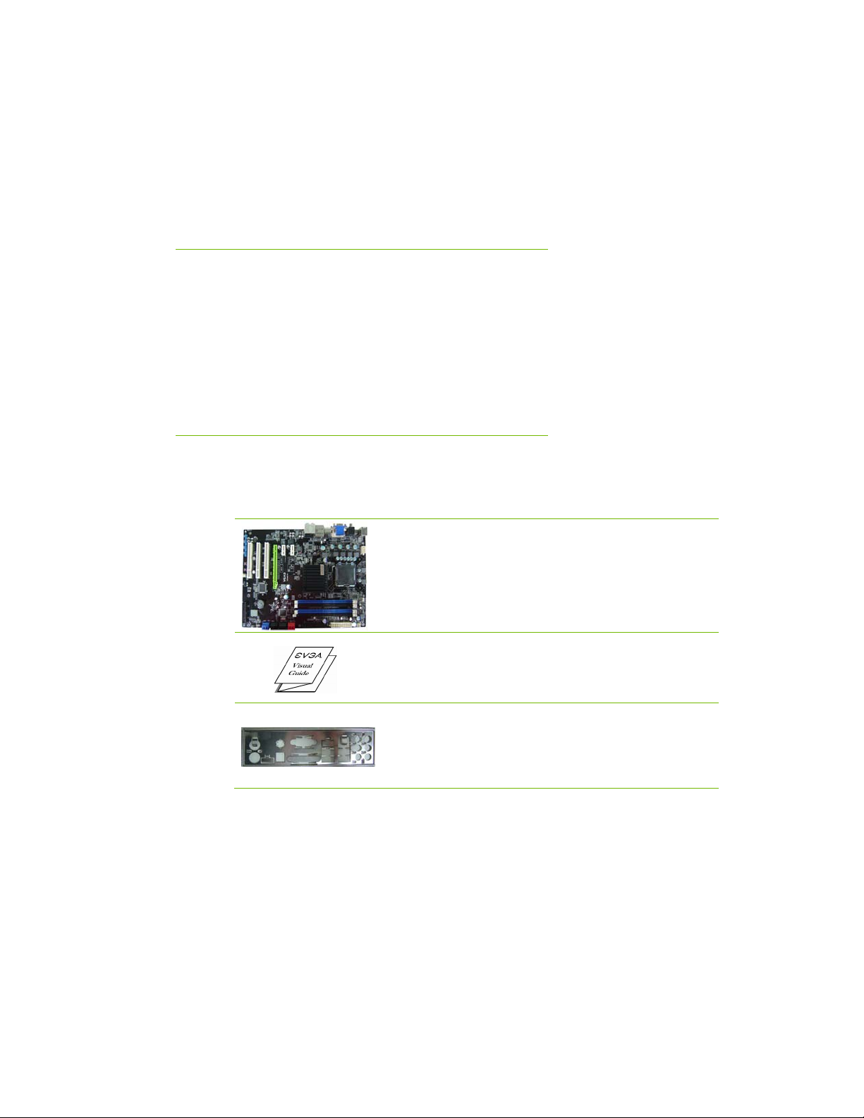
Unpacking
The EVGA nForce 730i motherboard comes with all the necessary cables for
adding a motherboard to a system case. If you are replacing a motherboard, you
may not need many of these cables.
All parts shipped in this kit are RoHS-compliant (lead-free) parts.
Equipment
Unpacking and
Parts Descriptions
The following equipment is included in the motherboard box.
The EVGA nForce 730i Motherboard
This PCI Express motherboard contains the
NVIDIA GeForce 9300 Chipset and is Hybrid SLIready.
1 - Visual Guide
Helps to quickly and visually guide you through
the hardware installation of the motherboard.
1 - I/O Shield
Installs in the system case to block radio
frequency transmissions, protect internal
components from dust, foreign objects, and aids
in proper airflow within the chassis.
EVGA
4
Page 16
Hardware Installation
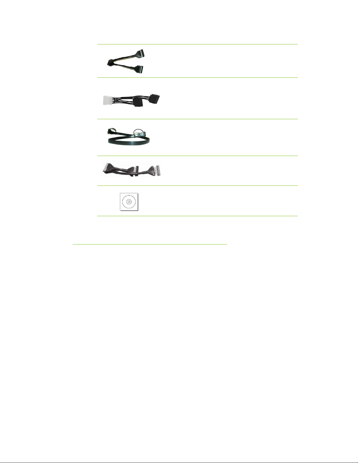
1 - Floppy Cable
Used to attach a floppy drive to the motherboard.
1 - 2-Port SATA Power Cable
Allows a Molex power connector to adapt to a
SATA power connector.
1 - Driver Installation CD
2 - SATA Signal Cable
Used to support the Serial ATA protocol and each
one connects a single drive to the motherboard.
1 - IDE-ATA 133 HDD Cable
Passes data between the IDE connection on the
motherboard and IDE device.
Contains drivers and software needed to setup the
motherboard.
EVGA nForce 730i
Motherboard
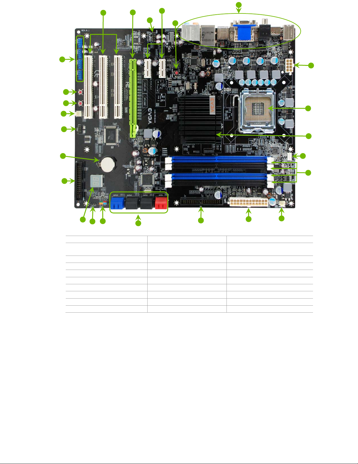
The EVGA nForce 730i motherboard with the NVIDIA GeForce
9300/nForce 730i single chip is a PCI Express, NVIDIA GeForce Boost
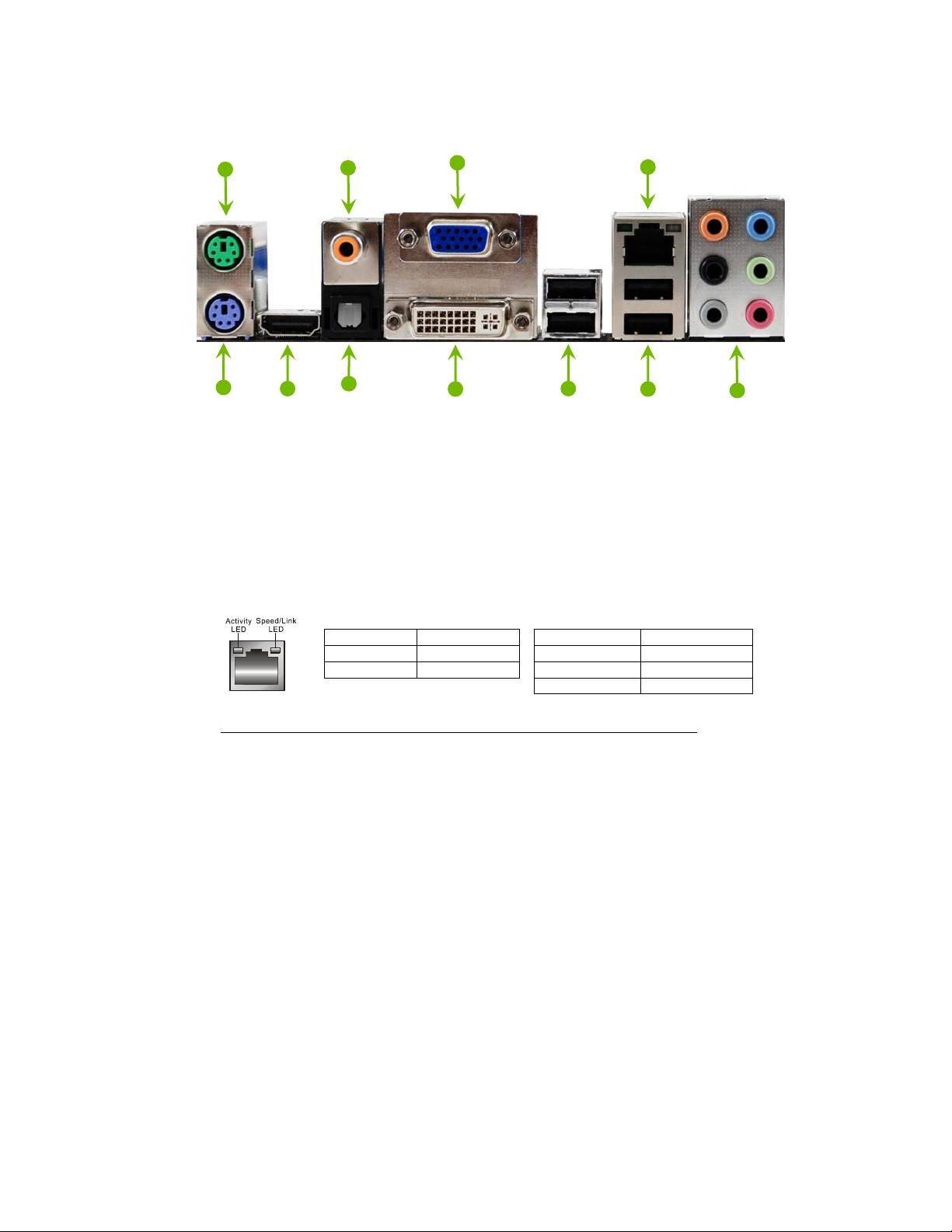
Technology ready motherboard. Figure 1 shows the motherboard and Figures 2
shows the back panel connectors.
5
EVGA
Page 17
24
22
21
23
19
20
18
17
16
15
14
13
12
11
1. CPU Socket – LGA 775 11. Diagnostic Code Display 21. PCI Express x1 Slot
2. NVIDIA SPP (with passive heat
sink)
3. CPU Fan Connector 13. Motherboard Battery 23. Clear CMOS Button
4. DDR2 DIMM Slots 1 - 4 14. Serial Port Connector 24. Back Panel Connectors (Figure 2)
5. Power Fan Connector 15. System Fan Connector 25. 8-pin ATX_12V Power Connector
6. 24-pin ATX Power Connector 16. Power Button
7. IDE Connector 17. RESET Button
8. Serial-ATA (SATA) Connectors 18. USB Headers
9. Front Panel Connector 19. PCI Slots
10. Speaker Connector 20. PCI Express x16 Slot
10
9
8
12. FDD Connector 22. Front Panel Audio Connector
7
6
5
25
1
2
3
4
Figure 1. EVGA nForce 730i Motherboard Layout
EVGA
6
Page 18
Hardware Installation
1
2
1. PS/2 Mouse Port
2. PS/2 Keyboard Port
3. HDMI Port
4. Coaxial SPDIF output
5. Optical SPDIF output
6. VGA Port
7. DVI-D Port
8. USB 2.0 Ports (Four)
9. LAN Port with LEDs to indicate status:
3
5
6
7
8 8
9 4
10
Activity LED Status Description
Off No data transmission
Blinking (Green) Data transmission
10. Audio Port 2-Channel 6-Channel 8-Channel________
Blue Line-In Line-In Line-In
Green Line-Out Front Speaker Out Front Speaker Out
Pink Mic In Mic In Mic In
Orange Center/Subwoofer Center/Subwoofer
Black Rear Speaker Out Rear Speaker Out
Grey Side Speaker Out
Speed/Link LED Status Description
Yellow 1000 Mbps data rate
Green 100 Mbps data rate
Off 10 Mbps data rate
Figure 2. Chassis Back Panel Connectors
7
EVGA
Page 19

Hardware Installation
This section will guide you through the installation of the motherboard. The
topics covered in this section are:
Preparing the motherboard
¾ Installing the CPU
¾ Installing the CPU fan
¾ Installing the memory
Installing the motherboard
Connecting cables and setting switches
Safety Instructions
EVGA
8
To reduce the risk of fire, electric shock, and injury, always follow basic
safety precautions.
Remember to remove power from your computer by disconnecting the
AC main source before removing or installing any equipment from/to the
computer chassis.
Page 20
Hardware Installation
Preparing the Motherboard
Installing the CPU
Be very careful when handling the CPU. Make sure not to bend or break any
pins in the socket. Hold the processor only by the edges and do not touch the
bottom of the processor.
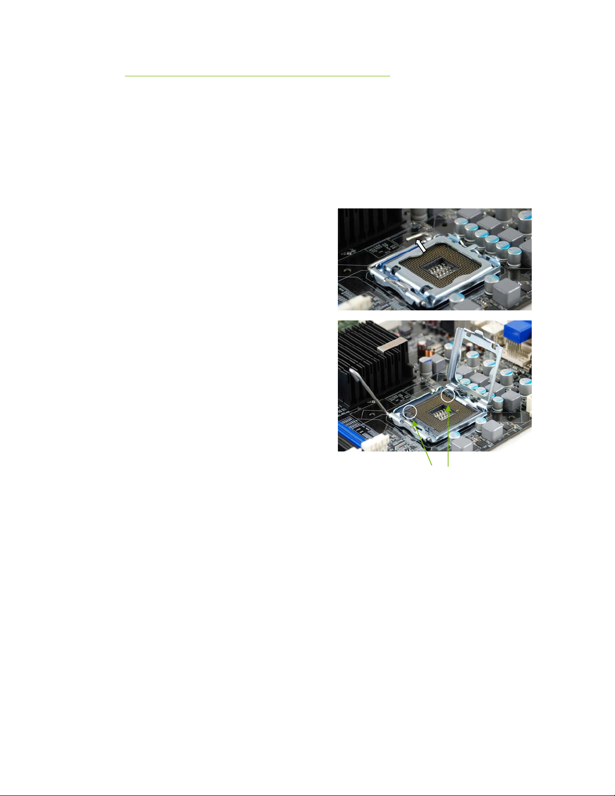
Use the following procedure to install
the CPU onto the motherboard.
1. Unhook the socket lever by
pushing down and away from the
socket.
2. Lift the load plate. There is a
protective socket cover on the
load plate to protect the socket
when there is no CPU installed.
3. Remove the protective socket
cover
from the load plate.
4. Remove the processor from its
protective
cover, making sure you hold it
only by
the edges. It is a good idea to save
the
cover so that whenever you remove the
CPU, you have a safe place to store it.
5. Align the notches in the processor with the
notches on the socket.
6. Lower the processor straight down into the socket
with out tilting or sliding it into the socket.
9
Align notches with
notches on the CPU
EVGA
Page 21
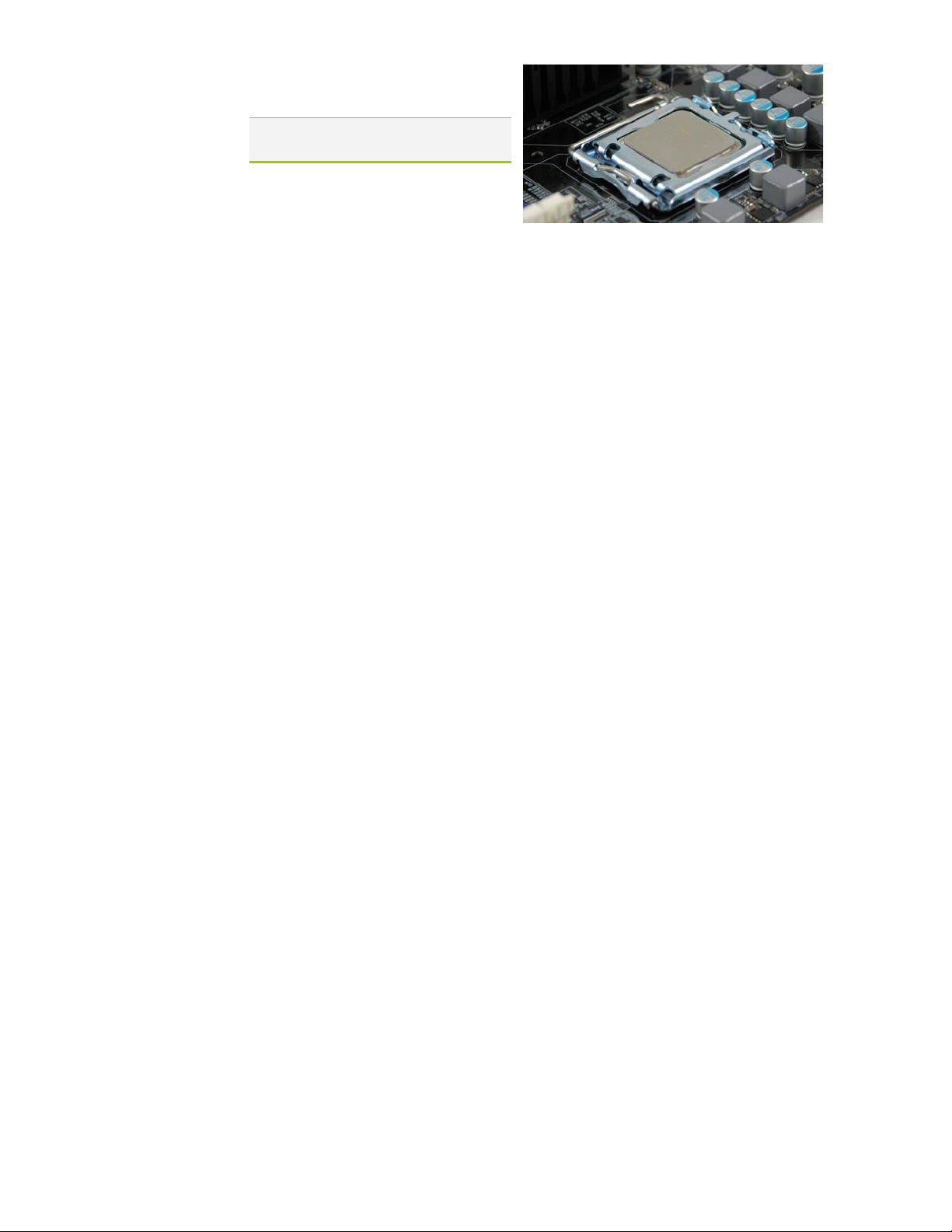
Note: Make sure the CPU is fully seated
and level in the socket.
7. Close the load plate over the CPU
and press down while you close
and engage the socket lever.
Installing the CPU Fan
There are many different fan types that can be used with this motherboard.
Follow the instruction that came with you fan assembly. Be sure that the fan
orientation is correct for your chassis type and your fan assembly.
Installing System Memory (DIMMs)
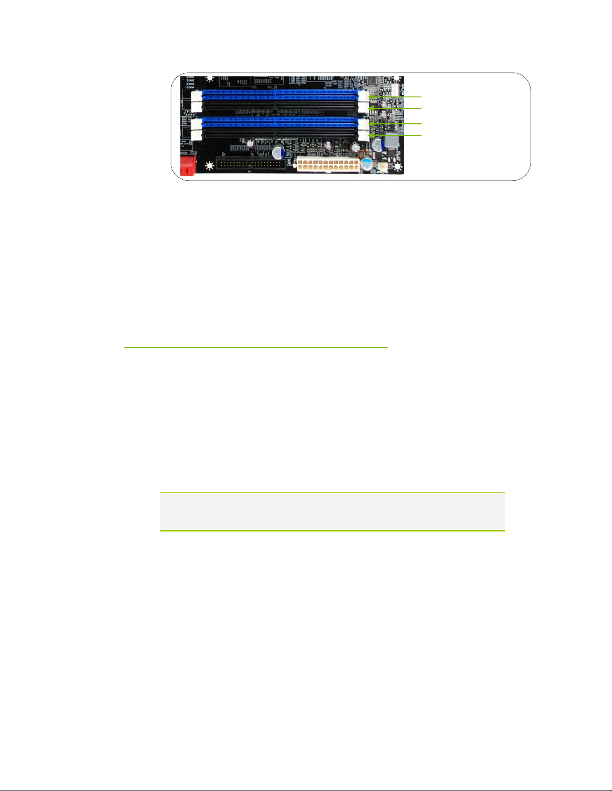
Your new motherboard has four 240-pin slots for DDR2-800 memory. These
slots support 256 MB, 512 MB,1 GB, and 2Gb DDR2. There must be at least
one memory bank populated to ensure normal operation. Use the following the
recommendations for installing memory. (See Figure 1 on page 6 for the
location of the memory slots.)
EVGA
10
One DIMM:
Install into slot 1. You can install the DIMM into any slot, however, slot 1 is
preferred.
Two DIMMs:
Install into either slots 1 and 3 or 2 and 4. The four DIMM sockets are
divided into two colors to help you identify the channel pairs. To obtain best
performance, simply mount DIMM sockets of the same color.
Four DIMMs:
Install into slots 1, 2, 3, and 4.
Page 22
Hardware Installation
Use the following procedure to install memory DIMMs. Note that there is only
one gap near the center of the DIMM slot. This slot matches the slot on the
memory DIMM to ensure the component is installed properly.
1. Unlock a DIMM slot by pressing the module clips outward.
2. Align the memory module to the DIMM slot and insert the module
vertically while applying light downward pressure to properly seat the
DIMM. The plastic clips at both sides of the DIMM slot automatically lock
the DIMM into the connector.
Installing the Motherboard
DIMM Slot 1
DIMM Slot 2
DIMM Slot 3
DIMM Slot 4
The sequence of installing the motherboard into the chassis depends on the
chassis you are using and if you are replacing an existing motherboard or
working with an empty chassis. Determine if it would be easier to make all the
connections prior to this step or to secure the motherboard and then make all
the connections. It is normally easier to secure the motherboard first.
Use the following procedure to install the I/O shield and secure the
motherboard into the chassis.
Note: Be sure that the CPU fan assembly has enough clearance for the chassis
covers to lock into place and for the expansion cards. Also make sure the
CPU Fan assembly is aligned with the vents on the covers.
11
EVGA
Page 23

Installing the I/O Shield
The motherboard kit comes with an I/O shield that is used to block radio
frequency transmissions, protects internal components from dust and foreign
objects, and promotes correct airflow within the chassis.
Before installing the motherboard, install the I/O shield from the inside of the
chassis. Press the I/O shield into place and make sure it fits securely. If the
I/O shield does not fit into the chassis, you would need to obtain the proper
size from the chassis supplier.
Securing the Motherboard into a System Case
Most computer cases have a base with mounting studs or spacers to allow the
mother board to be secured to the chassis and help to prevent short circuits. If
there are studs that do not align with a mounting hole on the motherboard, it is
recommended that you remove that stud to prevent the possibility of a short
circuit. In most cases, it is recommended to secure the motherboard using a
minimum of nine (9) spacers.
1. Carefully place the motherboard onto the studs/spacers located inside the
chassis.
Connecting Cables and Setting
Switches
EVGA
12
2. Align the mounting holes with the studs/spacers.
3. Align the connectors to the I/O shield.
4. Ensure that the fan assembly is aligned with the chassis vents according to
the fan assembly instruction.
5. Secure the motherboard with a minimum of eight-to-ten screws.
This section takes you through all the connections and switch settings necessary
on the motherboard. This will include:
Page 24

Hardware Installation
Power Connections
¾ 24-pin ATX power (
¾ 8-pin ATX 12V power (
PW1)
PW12)
Internal Headers
¾ Front panel
¾ Speaker
¾ USB Headers
¾ Audio
¾ COM
FDD
IDE
Serial ATA II
Chassis Fans
Expansion slots
CMOS Clear Button
See Figure 1 on page 6 to locate the connectors and Button referenced in the
following procedure.
13
EVGA
Page 25
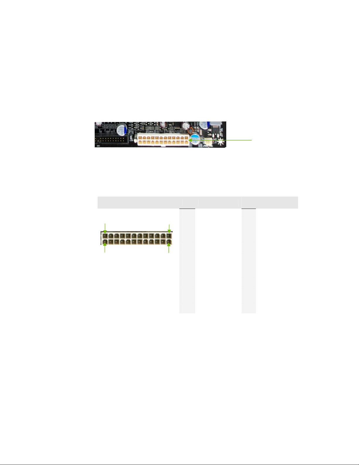
24-pin ATX Power
PW1 is the main power supply connector located along the edge of the board
(PW1)
next to the DIMM slots. Make sure that the power supply cable and pins are
properly aligned with the connector on the motherboard. Firmly plug the power
supply cable into the connector and make sure it is secure.
PW1 connector
Plug power cable from system
Card edge
power supply to PW1
Figure 2. PW1 Motherboard Connector
Table 1. PW1 Pin Assignments
Connector Pin Signal Pin Signal
24 13
12 1
1 +3.3V 13 +3.3V
2 +3.3V 14 -12V
3 GND 15 GND
4 +5V 16 PS_ON
5 GND 17 GND
6 +5V 18 GND
7 GND 19 GND
8 PWROK 20 RSVD
9 +5V_AUX 21 +5V
10 +12V 22 +5V
11 +12V 23 +5V
12 +3.3V 24 GND
EVGA
14
Page 26
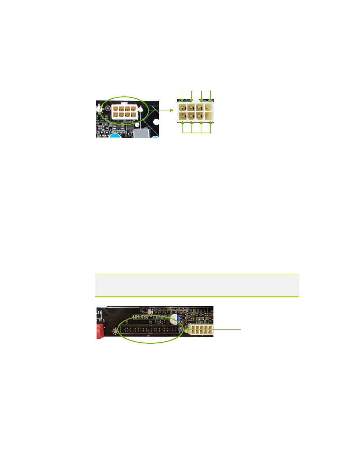
8-pin ATX 12V Power (PW12)
PW12, the 8-pin ATX 12V power connection, is used to provide power to the
CPU. Align the pins to the connector and press firmly until seated.
GND
1
4
5
12V
8
Connecting IDE Hard Disk Drives
The IDE connector supports Ultra ATA 133/100/66 IDE hard disk drives.
1. Connect the blue connector (the cable end with a single connector) to the
motherboard.
2. Connect the black connector (the cable with the two closely spaced black
and gray connectors) to the Ultra ATA master device.
3. Connect the gray connector to a slave device.
If you install two hard disk drives, you must configure the second drive as a
slave device by setting its jumper accordingly. Refer to the hard disk
documentation for the jumper settings.
Note: If an ATA-66/100 disk drive and a disk drive using any other IDE transfer
protocol are attached to the same cable, the maximum transfer rate between
the drives may be reduced to that of the slowest drive.
IDE Connector
Card-edge side
IDE Connector
EVGA
15
Page 27
T
TX-T
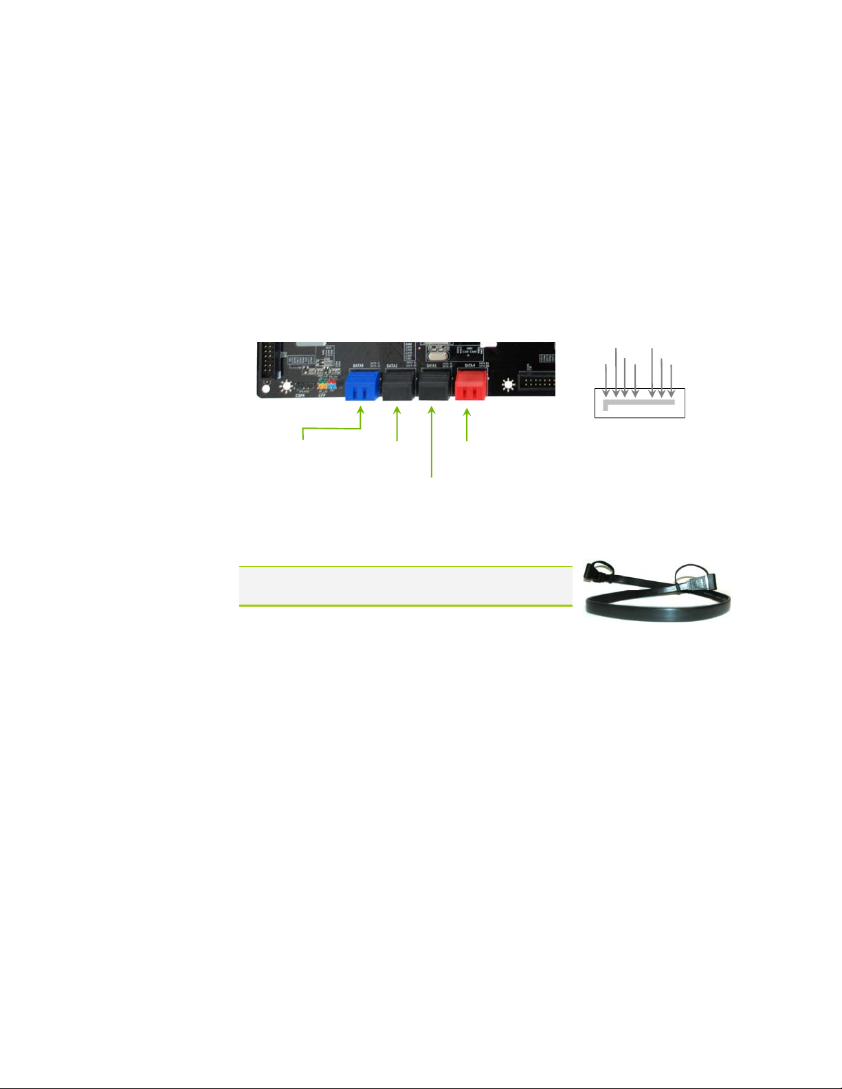
Connecting Serial ATA Cables
The Serial ATA II connector is used to connect the Serial ATA II device to the
motherboard. These connectors support the thin Serial ATA II cables for
primary storage devices. The current Serial ATA II interface allows up to
300MB/s data transfer rate.
There are eight (8) serial ATA II connectors on the motherboard. SATA ports 1
through 3 support RAID 0, RAID 1, RAID 5, RAID 0+1 and JBOD
configurations. The SATA 4 port uses the JMicron JMB363 and only supports
RAID 0, RAID 1.
GND
X-
RX+
GND
X+
GND
SATA 3
SATA C1 (top)
SATA C0 (bottom)
SATA 2
SATA B1 (top)
SATA B0 (bottom)
SATA 4
SATA D1 (top)
SATA D0 (bottom)
SATA 1
SATA A1 (top)
SATA A0 (bottom)
Connect the locking cable
end to the motherboard
connector.
Connect the end without
the lock to the drive.
Note: The SATA3 port only supports AHCI and RAID
mode. It does not support IDE mode.
EVGA
16
Page 28
Hardware Installation
Connecting Internal Headers
Front Panel Header
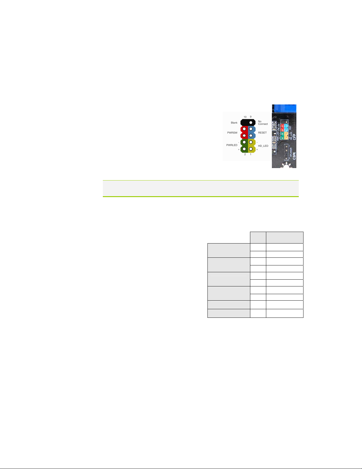
The front panel header on this motherboard is one connector used to connect
the following four cables.
(see Table 2 for pin definitions):
PWRLED
Attach the front panel power LED
cable to these two pins of the connector.
The Power LED indicates the system’s
status. When the system is turn on status,
the LED is on. When the system is turn off
status, the LED is off. When the system is
in S1, S1, S3, S4 status, the LED is blink.
Some chassis do not have all four cables. Be sure to match the name on the
connectors to the corresponding pins.
Card-edge
side
PWRSW
Attach the power button cable from
the case to these two pins. Pressing
Table 2.Front Panel Header Pins
the power button on the front panel
turns the system on and off rather
than using the power supply button.
HD_LED
Attach the hard disk drive indicator
LED cable to these two pins. The
HDD indicator LED indicates the
activity status of the hard disks.
RESET
Attach the Reset switch cable from
the front panel of the case to these
Pin Signal
HD_LED
PWRLED
RESET
PWRSW
No Connect 9 +5V
Empty 10 Empty
1 HD_PWR
3 HD Active
2 PWR LED
4 STBY LED
5 Ground
7 RST BTN
6 PWR BTN
8 Ground
two pins. The system restarts when
RESET switch is pressed.
the
17
EVGA
Page 29
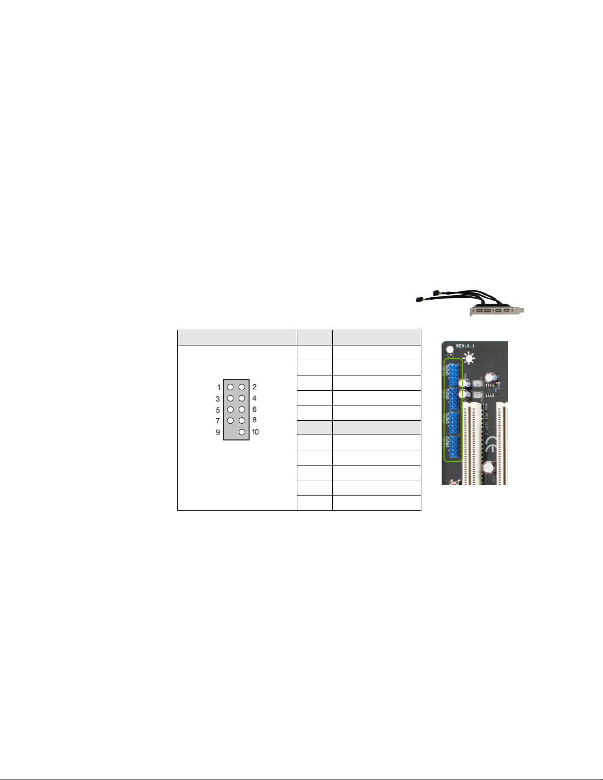
USB Headers
This motherboard contains four (4) USB 2.0 ports that are exposed on the rear
panel of the chassis (Figure 2). The motherboard also contains four 10-pin
internal header connectors onboard that can be used to connect an optional
external bracket containing eight (8) more USB2.0 ports.
1. Secure the bracket to either the front or rear panel
of your chassis (not all chassis are equipped with the
front panel option).
2. Connect the two ends of the cables to the USB 2.0
headers on the motherboard.
Table 3. USB 2.0 Header Pins
EVGA
18
Connector Pin Signal
1 5V_DUAL
USB 2.0 Header
3 Data-
5 Data+
7 GND
9 Empty
Pin Signal
2 5V_DUAL
4 Data-
6 Data+
8 GND
10 No Connect
Card Edge
Page 30
Hardware Installation
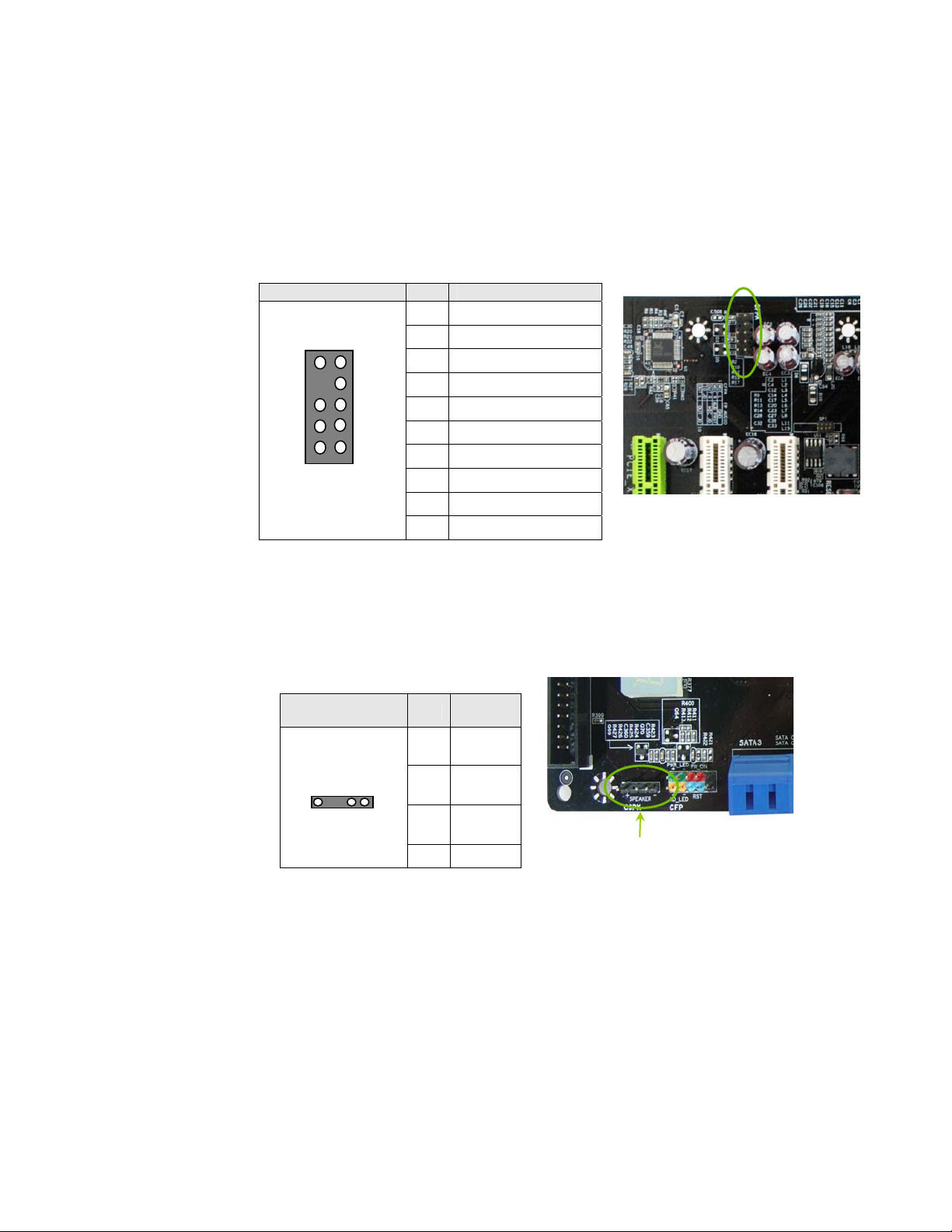
Audio
The audio connector supports HD audio standard and provides two kinds of
audio output choices: the Front Audio, the Rear Audio. The front Audio
supports re-tasking function.
Table 4. Front Audio Connector
Connector Pin Signal
1 PORT1_L
Front Audio Connector
10
8
6
4
2
9
7
5
3
1
2 AUD_GND
3 PORT1_R
4 PRECENCE_J
5 PORT2_R
6 SENSE1_RETURN
7 SENSE_SEND
8 Empty
9 PORT2_L
10 SENSE2_RETURN
SPK Header
The speaker header is connects to the case’s speaker for PC beeps.
Table 5. CSPK Header Pins
Connector Pin Signal
Speaker Header
1 VCC
2 Empty
Card Edge
1 2 3 4
3 GND
4 Speaker
Speaker Header
19
EVGA
Page 31
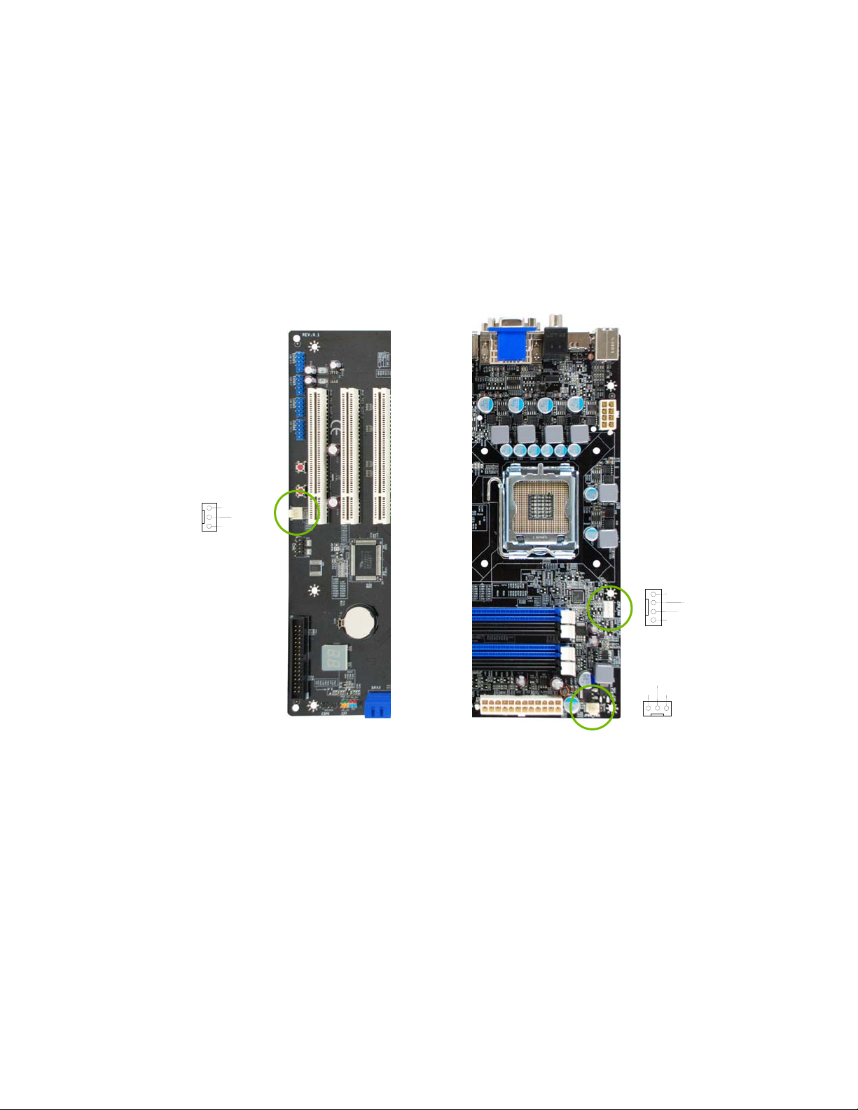
Fan Connections
There are three fan connections on the motherboard. The fan speed can be
detected and viewed in the
fans are automatically turned off after the system enters S3, S4 and S5mode.
PC Health Status section of the CMOS Setup. The
EVGA
20
System Fan
Sense
+12V
Ground
Note: The CPU fan cable can be either a 3-pin or a 4-pin
connector. Connect a 3-pin connector to pins 1, 2, and 3 on the
motherboard connector.
CPU Fan
Power Fan
+12V
Sense
Ground
Ground
Sense
Control
+12V
Page 32
Hardware Installation
COM1
The motherboard kit provides an additional serial COM header for your
machine. Connect one side of a switching cable to the header and then attach
the serial COM device to the other side of the cable.
FDD Connector
The motherboard supports a standard 360K, 720K, 1.2M, 1.44m, and a 2.88M
floppy disk drive (FDD).
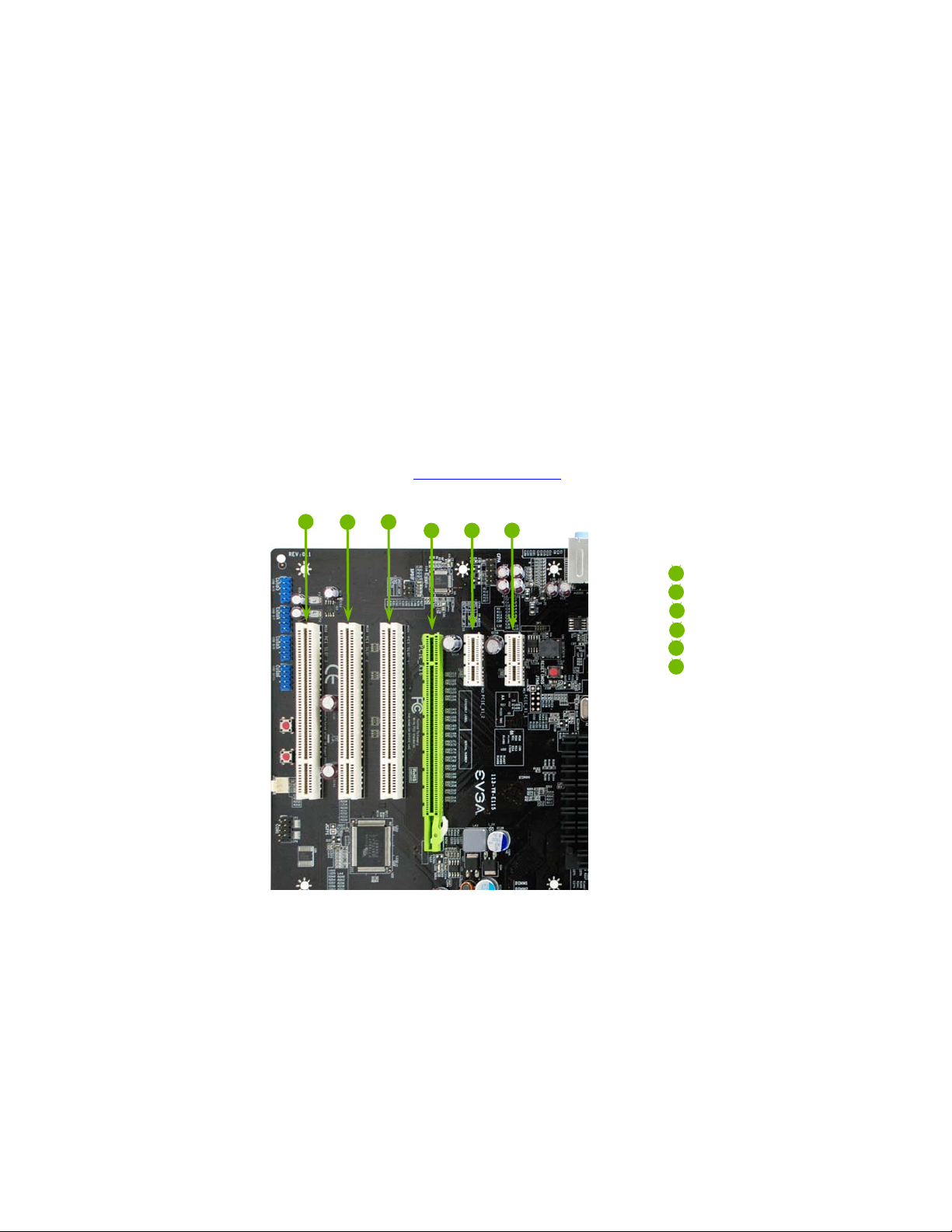
Expansion Slots
This motherboard contains six expansion slots, three PCI Express slots and
three PCI slots. For a full list of PCI Express x16 graphics card supported by
this motherboard, go to
2
www.nvidia.com/estore.
31
5
4
6
1 – PCI slot 3
2 – PCI slot 2
3 – PCI slot 1
4 – PCI-E x16 slot
5 – PCI-E x1 slot
6 – PCI-E x1 slot
21
EVGA
Page 33

PCI Slots
The three PCI slots support many expansion cards such as a LAN card, USB
card, SCSI card and other cards that comply with PCI specifications. When
installing a card into the PCI slot, be sure that it is fully seated. Secure the card’s
metal bracket to the chassis back panel with the screw used to hold the blank
cover.
PCI Express x1 Slots
There are two PCI Express x1 slots that are designed to accommodate less
bandwidth-intensive cards, such as a modem or LAN card. The x1 slots provide
250 MB/sec bandwidth.
PCI Express x16 Slot
The PCI Express x16 slot is reserved for graphic or video cards. The bandwidth
of the x16 slot is up to 4GB/sec (8GB/sec concurrent).
When installing a PCI Express x16 card, be sure the retention clip snaps and
locks the card into place. If the card is not seated properly, it could cause a
short across the pins. Secure the card’s metal bracket to the chassis back panel
with the screw used to hold the blank cover.
EVGA
22
Page 34
Hardware Installation
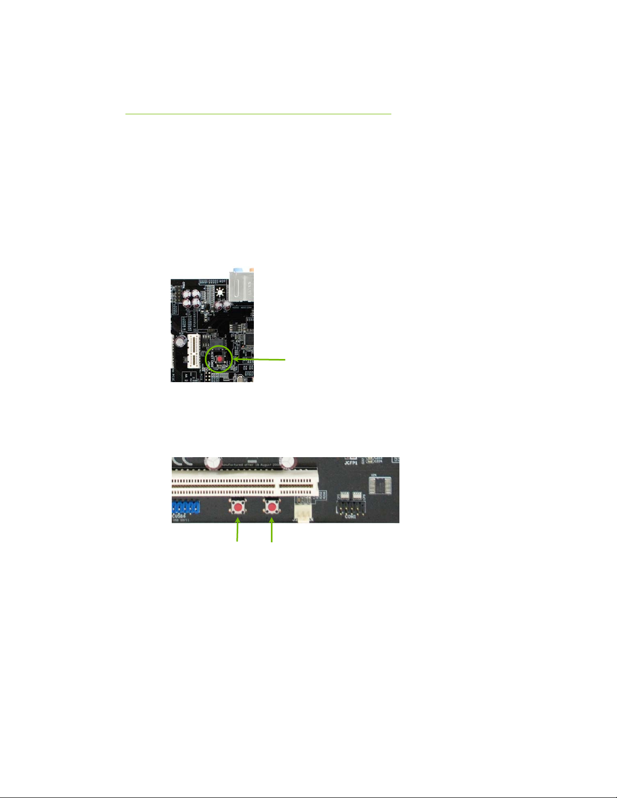
Onboard Buttons
The onboard buttons include RESET, POWER and CMOS. The functions
allow you turn on/off and easily and conveniently clear the CMOS.
Clear CMOS Button
The motherboard uses the CMOS RAM to store all the set parameters within
the system BIOS. The CMOS can be cleared by press the RESET CMOS
button.
Clear CMOS
Button
RESET and POWER Button
These onboard buttons allow you to easily turn the system ON or OFF. It is
especially convenient for debugging or testing the system.
RESET
Button
23
POWER
Button
EVGA
Page 35
Post Port Debug LED and LED
Status Indicators
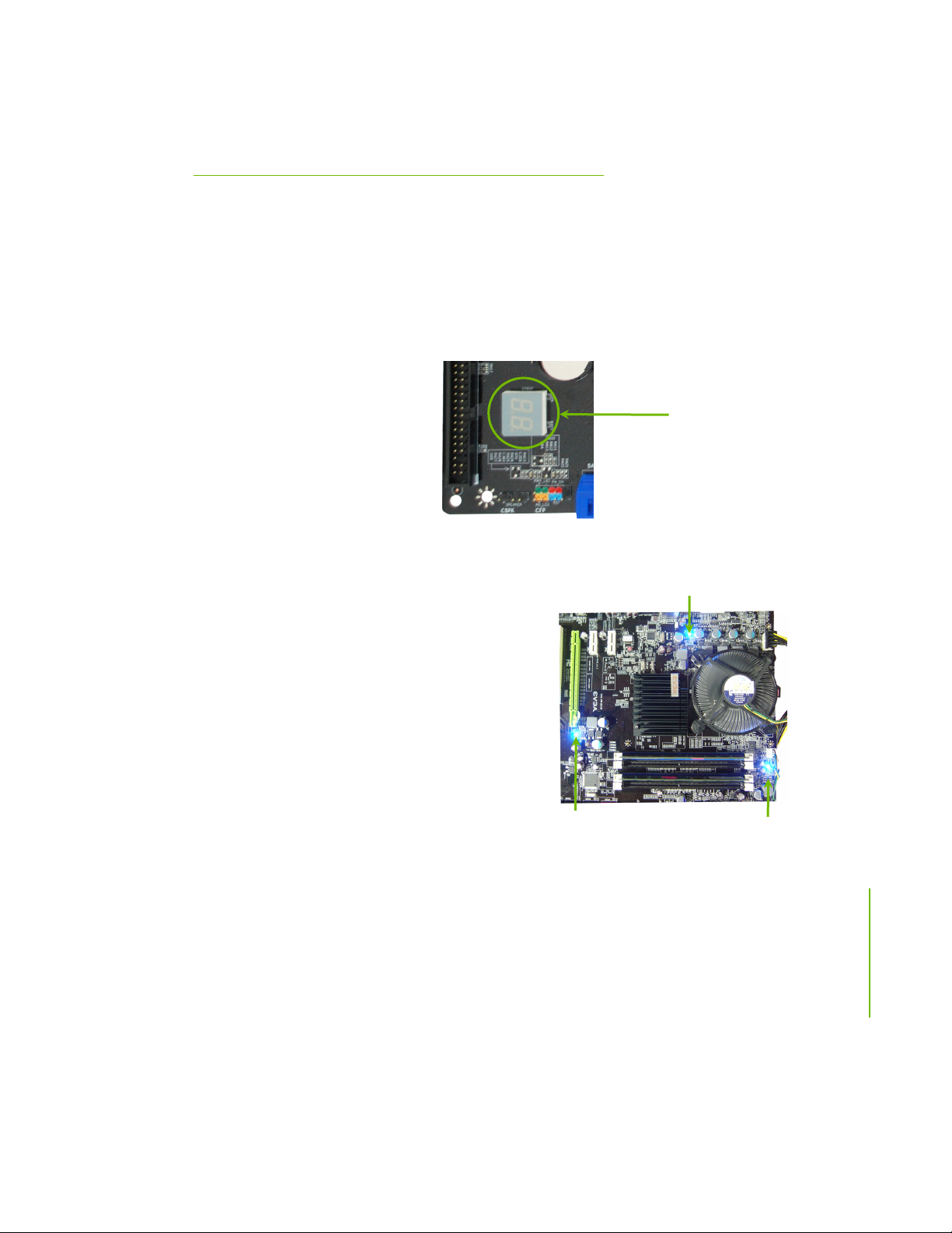
Post Port Debug LED
Provides two-digit POST codes to show why the system may be failing to boot.
The LED will also display the CPU temperature after entering the O/S.
Debug LED
LED Status Indicators
Theses LEDs indicate the system’s status.
DIMM LED (LED1):
This LED to show the power status of
Memory.
CHIPSET LED (LED2):
This LED to show the power status
of Chipset.
CPU LED (LED3):
This LED to show the power status of
CPU.
EVGA
25
CHIPSET LED
CPU LED
DIMM LED
Page 36

Configuring the BIOS
This section discusses how to change the system settings through the BIOS
Setup menus. Detailed descriptions of the BIOS parameters are also provided.
This section includes the following information:
Enter BIOS Setup
Main Menu
Standard CMOS Features
Advanced BIOS Features
Advanced Chipset Features
Integrated Peripherals
Power Management Setup
PnP/PCI Configurations
PC Health Status
Frequency/Voltage Control
EVGA
26
Page 37
Configuring the BIOS
Enter BIOS Setup
The BIOS is the communication bridge between hardware and software.
Correctly setting the BIOS parameters is critical to maintain optimal system
performance.
Use the following procedure to verify/change BIOS settings.
1. Power on the computer.
2. Press the Del key when the following message briefly displays at the bottom
of the screen during the Power On Self Test (POST).
Press F1 to continue, DEL to enter Setup.
Pressing Del takes you to the Phoenix-Award BIOS CMOS Setup Utility.
It is strongly recommended that you do not change the default BIOS settings.
Changing some settings could damage your computer.
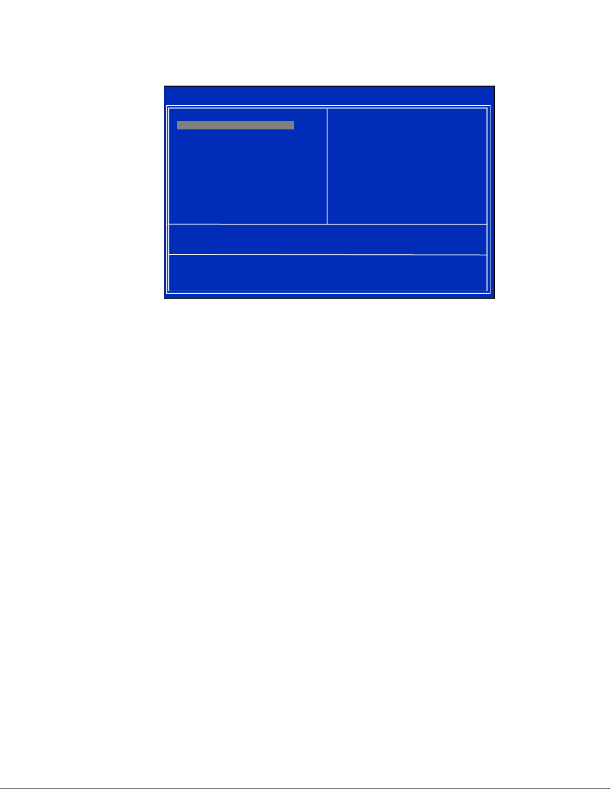
Main Menu
The main menu allows you to select from the list of setup functions and two
exit choices. Use the
options or press
keys to position the selector in the option you choose. To go back to the
previous menu, press
Note that on the BIOS screens all data in white is for information only, data in yellow
is changeable, data in blue is non-changeable, and data in a
red box is highlighted for selection.
27
Page Up and Page Down keys to scroll through the
Enter to display the associated submenu. Use the arrow
Esc.
EVGA
Page 38
g
Phoenix – AwardBIOS CMOS Setup Utility
` Standard CMOS Features
` Advanced BIOS Features
` Advanced Chipset Features
` Integrated Peripherals
` Power Management Setup
` PnP/PCI Configurations
Esc : Quit
F10 : Save & Exit Setup
Time, Date, Hard Disk Type..,
` Frequency/Voltage Control
Load Fail-Safe Defaults
Load Optimized Defaults
Set Supervisor Password
Set User Password
Save & Exit Setup
Exit Without Savin
: Select Item
Figure 3. BIOS CMOS Setup Utility Main Menu
Standard CMOS Features
Use this menu to set up the basic system configuration.
Advanced BIOS Features
Use this menu to set up the advanced system features and boot sequence.
EVGA
28
Advanced Chipset Features
Use this menu to optimize system performance and configure clocks,
voltages, memory timings, and more.
Integrated Peripherals
Use this menu to set up onboard peripherals such as IDE, RAID, USB, LAN,
and MAC control.
Power Management Setup
Use this menu to configure power management, power on, and sleep features.
PnP/PCI Configurations
Use this menu to modify the system’s Plug-and-Play and PCI configurations.
Page 39

Configuring the BIOS
PC Health Status
Use this menu to monitor the real-time system status of your PC, including
temperature, voltages, and fan speed.
The following items on the CMOS Setup Utility main menu are commands
rather than submenus:
Load Fail-Safe Defaults
Load Fail-Safe defaults system settings.
Load Optimized Defaults
Load Optimized defaults system settings.
Set Supervisor Password/Set User Password
Use this command to set, change, and disable the password used to access the
BIOS menu.
Save & Exit Setup
Use this command to save settings to CMOS and exit setup.
Exit Without Saving
Use this command to abandon all setting changes and exit setup.
29
EVGA
Page 40
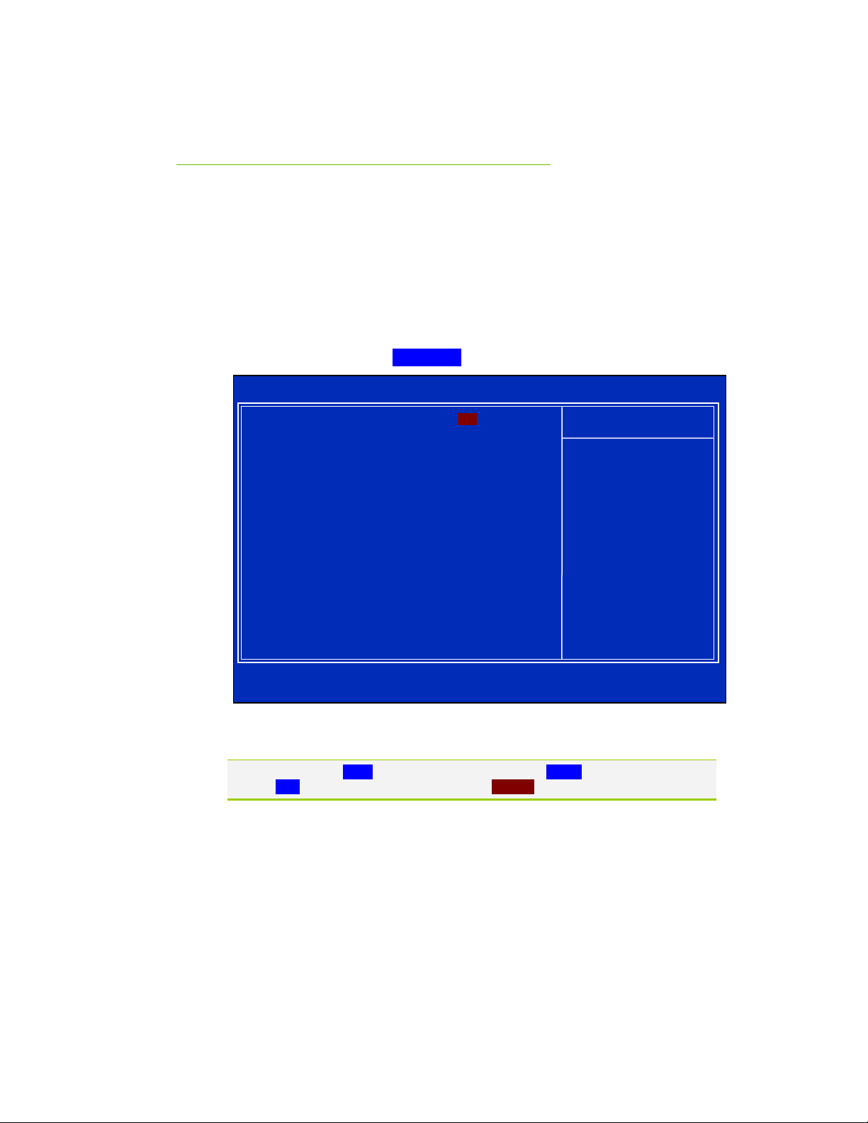
p
Standard CMOS Features
Menu
The Standard CMOS Features menu is used to configure the standard CMOS
information, such as the date, time, HDD model, and so on. Use the
and Page Down keys to scroll through the options or press Enter to display the
sub-menu. Use the arrow keys to position the selector in the option you
choose. To go back to the previous menu, press
The information shown in Item Help corresponds to the option highlighted.
Page Up
Esc.
Phoenix – AwardBIOS CMOS Setup Utility
Date (mm:dd:yy) Sat, Jul 01 2006
Time (hh:mm:ss) 12 : 48: 23
` IDE Channel 0 Master [None]
` IDE Channel 0 Slave [None]
` SATA 1 (A0) [None]
` SATA 2 (A1) [None]
` SATA 3 (B0) [None]
` SATA 4 (B1) [None]
` SATA 5 (C0) [None]
` SATA 6 (C1) [None]
Drive A [1.44, 3.5 in.]
Halt On [All , But Keyboard]
Base Memory 640K
Extended Memory 1047552K
Total Memory 1048576K
:Move Enter:Select +/-/PU/PD:Value F10:Save ESC:Exit F1:General Help
F5:Previous Values F6:Fail-Safe Defaults F7:O
Standard CMOS Features
Item Help
Main Level `
Change the day, month,
year and century
timized Defaults
Figure 4. Standard CMOS Features Menu
Note that all data in white is for information only, data in yellow is changeable, data in
blue is non-changeable, and data in a red box is highlighted for selection.
EVGA
30
Page 41
Configuring the BIOS
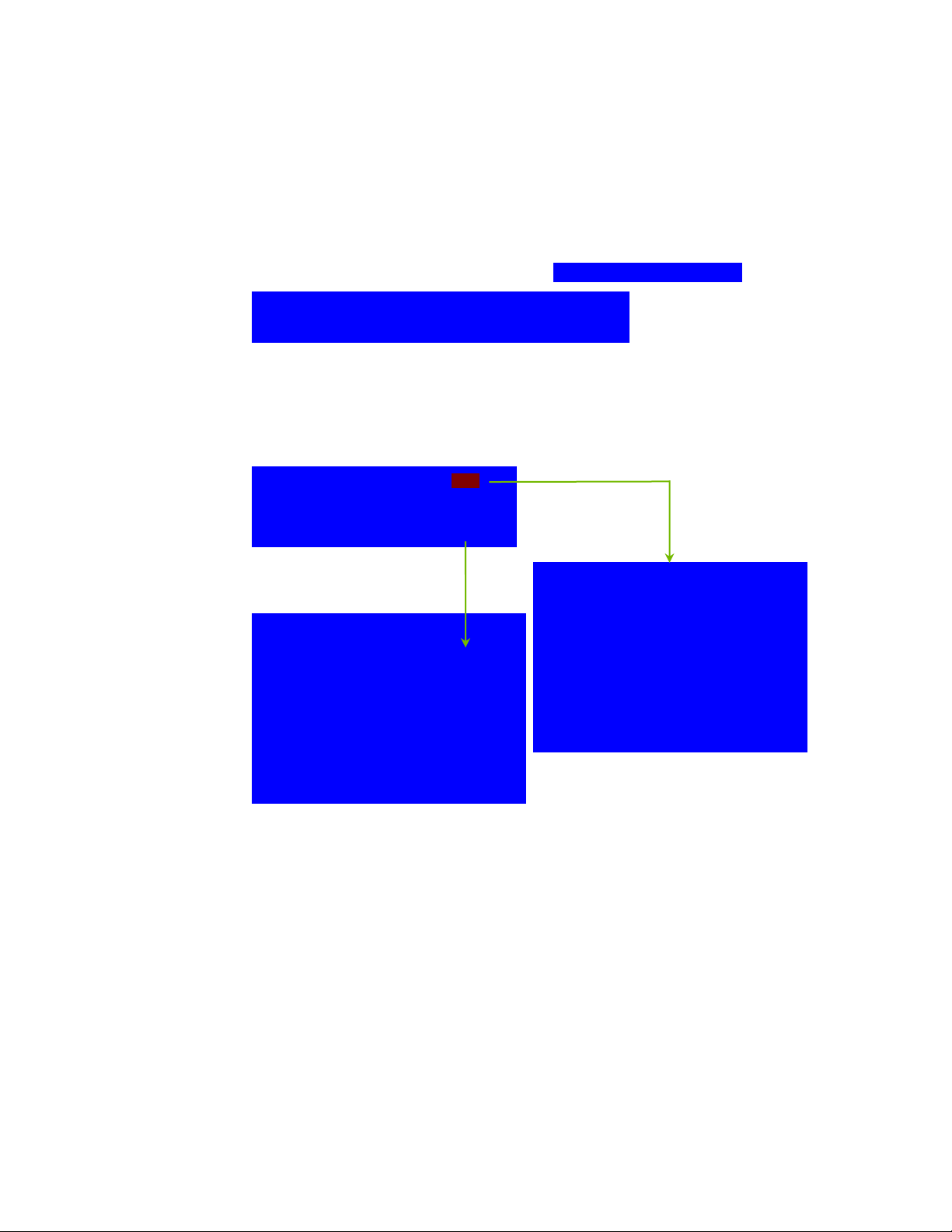
Date and Time
Using the arrow keys, position the cursor over the month, day, and year. Use
Page Up and Page Down keys to scroll through dates and times. Note that
the
the weekday (Sun through Sat) cannot be changed. This field changes to
correspond to the date you enter. Note that the hour value is shown in a
24-hour clock format. Time is represented as hour : minute : second.
Date (mm:dd:yy) Sat, Jul 01 2006
Time (hh:mm:ss) 14 : 48: 43
SATA Channel
Use these functions to detect and configure the SATA channels. Select a
channel and press
` SATA 1 (A0) [None]
` SATA 2 (B0) [None]
` SATA 1 (A1) [None]
` SATA 2 (B1) [None]
Press ENTER to display
SATA Channel sub-menu
IDE Auto-Detect [Press Enter]
SATA 1 (A0) [None}
Access Mode Auto
Capacity 0 MB
Cylinder 0
Head 0
Precomp 0
Landing Zone 0
Sector 0
Enter to display the SATA sub-menu.
Press ENTER to display
IDE Channel sub-menu
IDE HDD Auto-Detect [Press Enter]
SATA 1 (A0) [Manual}
Access Mode [CHS]
Capacity 0 MB
Cylinder [ 0]
Head [ 0]
Precomp [ 0]
Landing Zone [ 0]
Sector [ 0]
31
EVGA
Page 42
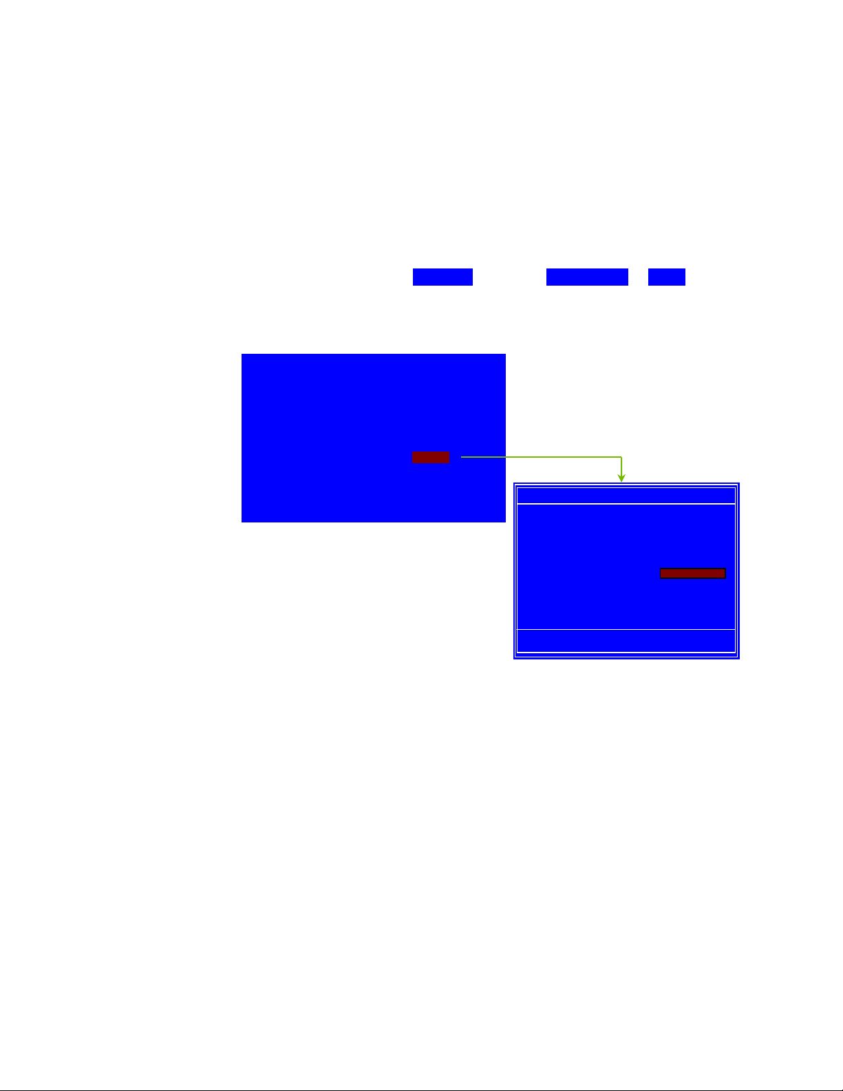
Press Enter to auto-detect SATA channels in the system. Once the channel is
detected, the values for Capacity, Cylinder, Heads, Precomp, Landing Zone, and
Sector are automatically filled in.
None
There is no HDD installed or set.
Auto
The system can auto-detect the hard disk when booting up.
Manual
When you set the channel to [Manual] and change Access Mode to [CHS],
you can then enter the number of cylinders, heads, Precomp, landing zone,
and sector. You can manually enter the values or you can press
Enter to
display a window that tells you the min and max values.
IDE HDD Auto-Detect [Press Enter]
SATA 1 (A0) [Manual}
Access Mode [CHS]
Capacity 0 MB
Cylinder .....0
Head [ 0]
Precomp [ 0]
Landing Zone [ 0]
Sector [ 0]
The BIOS supports the following HDD
Access Modes:
¾ CHS
For HDD less than 528 MB.
¾ LBA
For HDD greater than 528 MB and
Press ENTER to display submenu
Cylinder
Min= 0
Max=65535
Key in a DEC number :
:Move ENTER:Accept ESC:Abort
supporting LBA (Logical Block
Addressing).
¾ Large
For HDD greater than 528 MB but not supporting LBA.
¾ Auto
Recommended mode.
EVGA
32
Page 43
Configuring the BIOS
[
]
Drive A
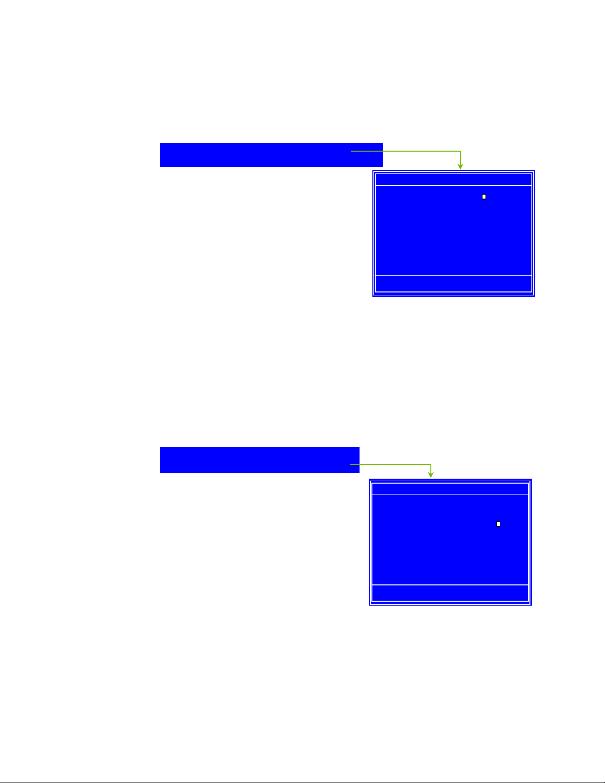
The Drive A option allows you to select the kind of FDD to install.
Options are:
Drive A [1.44, 3.5 in.]
Halt On
None
360K, 5.25 in.
1.2M, 5.25 in.
720K, 3.5 in.
1.44M, 3.5 in.
2.88M, 3.5 in.
Use the
through the options or press
the sub-menu. Use the arrow keys to
position the selector in the option you choose. Press
changes and return to the Standard CMOS Features menu.
All, But Keyboard
Page Up and Page Down keys to scroll
Enter to display
-
Drive A
None ..... [
360K, 5.25 in. ..... [ ]
1.2M, 5.25 in. ..... [ ]
720K, 3.5 in. ..... [ ]
1.44M, 3.5 in. ..... [ ]
2.88M, 3.5 in. ..... [ ]
:Move ENTER:Accept ESC:Abort
Enter to accept the
]
Halt On
Halt On determines whether or not the computer stops if an error is detected
during power on. Use the
options or press
Enter to display the Halt On sub-menu. Use the arrow keys
to position the selector in the option you choose. Press
changes and return to the Standard CMOS Features menu.
Drive A [1.44, 3.5 in.]
Halt On [All , But Keyboard]
All Errors
Whenever the BIOS detects a nonfatal
error, the system stops and prompts you.
33
Page Up and Page Down keys to scroll through the
Enter to accept the
Press ENTER to display sub-menu
Halt On
All Errors ..... [ ]
No Errors ..... [ ]
All , But Keyboard ..... [
All , But Diskette ..... [ ]
All , But Disk/Key ..... [ ]
:Move ENTER:Accept ESC:Abort
]
EVGA
Page 44

No Errors
S
ystem boot does not stop for any detected errors.
All, But Keyboard
System boot does not stop for keyboard errors, but does stop for all other
errors.
All, But Diskette
The system boot does not stop for a diskette error but will stop for all other
errors.
All, But Disk/Key
The system boot does not stop for a keyboard or disk error, but will stop for
all other errors.
Memory
These settings are display-only values that are determined by the BIOS POST
(Power-On Self Test).
Base Memory
BIOS POST determines the
amount of base (or conventional) memory installed in the system.
Extended Memory
BIOS determines how much extended memory is present during the POST.
Total Memory
This value represents the total memory of the system.
Base Memory 640K
Extended Memory 1047552K
EVGA
34
Page 45
Configuring the BIOS
p
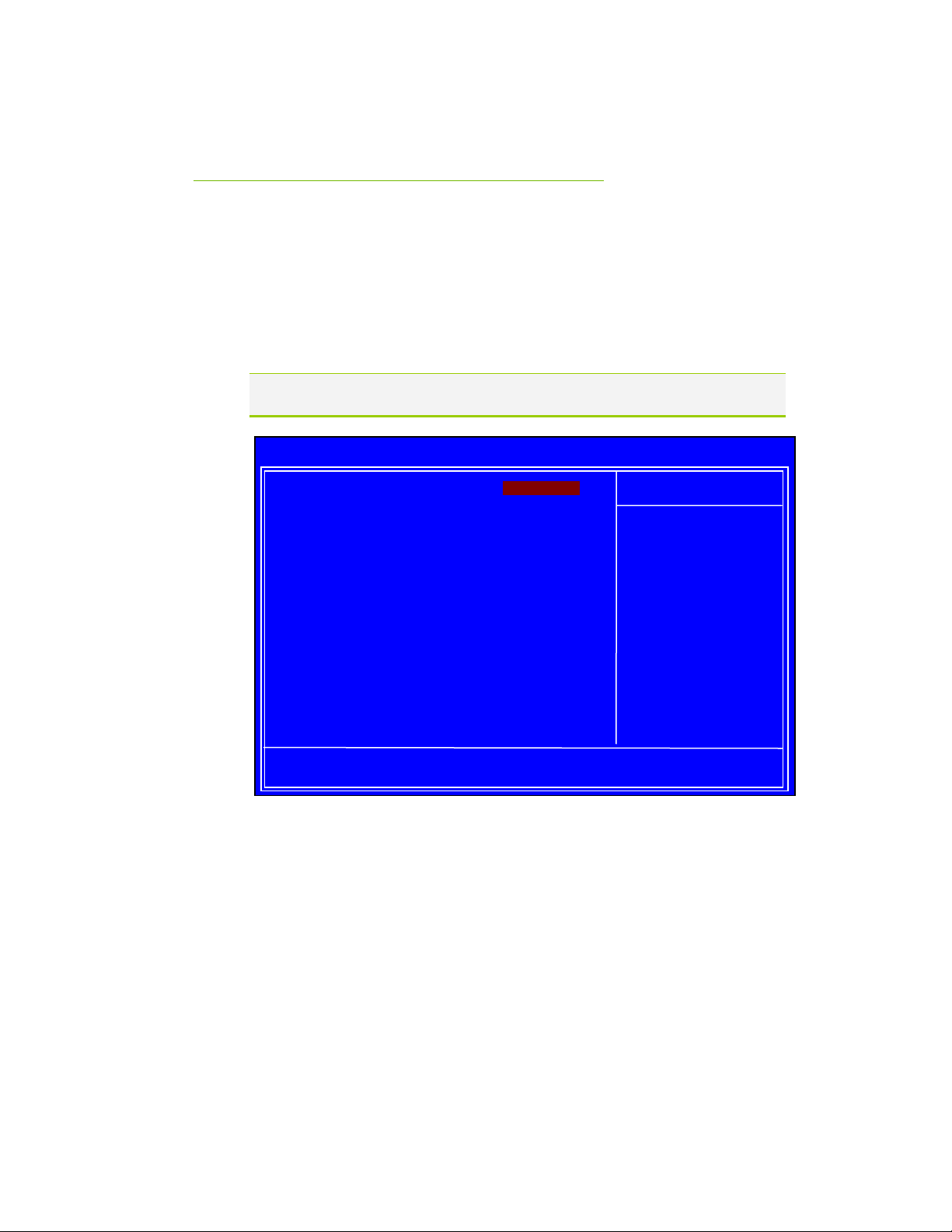
Advanced BIOS Features
Menu
Access the Advanced BIOS Features menu from the CMOS Utility Setup
screen. Use the
Enter to display the sub-menu. Use the arrow keys to position the
press
selector in the option you choose. To go back to the previous menu, press
The options that have associated sub-menus are designated by a `, which precedes
the option. Press Enter to display the sub-menus.
Page Up and Page Down keys to scroll through the options or
Esc.
Phoenix – AwardBIOS CMOS Setup Utility
` Removable Device Priority [Press Enter]
` Hard Disk Boot Priority [Press Enter]
` CD-ROM Boot Priority [Press Enter]
First Boot Device [Removable]
Second Boot Device [CDROM]
Third Boot Device [Hard Disk]
Boot Other Device [Enabled]
Boot Up NumLock Status [On]
Security Option [Setup]
APIC Mode [Enabled]
MPS Version Control For OS [1.4]
Full Screen LOGO Show [Disabled]
:Move Enter:Select +/-/PU/PD:Value F10:Save ESC:Exit F1:General Help
F5:Previous Values F6:Fail-Safe Defaults F7:O
Advanced BIOS Features
Main Level `
Select Removable Boot
Device Priority
timized Defaults
Figure 5. Advanced BIOS Features Menu
Item Help
35
EVGA
Page 46
d
p
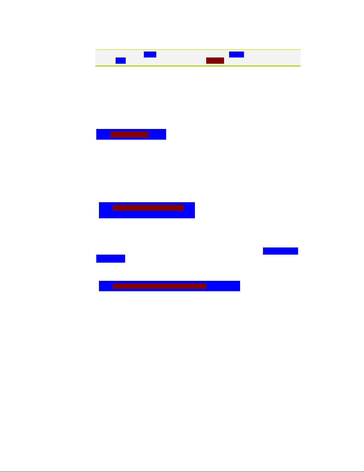
Note that all data in white is for information only, data in yellow is changeable, data in
blue is non-changeable, and data in a red box is highlighted for selection.
Removable Device Priority
Use this option to select the priority for removable device startup. Press Enter
to see the list of removable devices in your system. Use the arrow keys to go
to the various devices. Then use the
or down in the list. To go back to the previous menu, press
+ or – keys to move the device priority up
Esc.
1. Floppy Disks
Hard Disk Boot Priority
Use this option to select the priority for HDD startup. Press Enter to see the
list of bootable devices in your system. Use the arrow keys to go to the
various devices. Then use the
+ or – keys to move the device priority up or
down in the list. To go back to the previous menu, press
1. Ch0. : ST3802110A
2. Bootable Ad
-in Cards
CD-ROM Boot Priority
Use this option to select the priority for CD-ROM startup. Select CD-ROM Boot
Priority and press Enter to view available networks. Use the arrow keys
to go to the various devices. Then use the
priority up or down in the list. To go back to the previous menu, press
1. Ch0 M. : BENQ DVD DC DW1810
Esc.
Use the + and – keys to move
riority of the device within
the
+ or – keys to move the device
Esc.
First/Second/Third Boot Device
Use this option to set the priority sequence of the devices booted at power on.
Use the
EVGA
36
Page Up and Page Down keys to scroll through the options or press
Page 47

Configuring the BIOS
Enter to display the sub-menu. Use the arrow keys to position the selector
in the option you choose.
First Boot Device
Removable ..... [
Hard Disk ..... [ ]
CDROM ..... [ ]
Legacy LAN ..... [ ]
NVIDIA Boot Age ..... [ ]
Disabled ..... [ ]
:Move ENTER:Accept ESC:Abort
Boot Other Device
With the option set to Enable, the system boots from some other device if the
first/second/third boot devices fail.
]
Boot Up NumLock Status
This option allows you to select the power-on state of NumLock. Select On to
activate the keyboard NumLock when the system is started. Select Off to disable
NumLock key.
the
Security Option
The Security Options allows you to require a password every time the system
boots or only when you enter setup. Select Setup to require a password to gain
access to the CMOS Setup screen. Select System to require a password to
access the CMOS Setup screen and when the system boots.
37
EVGA
Page 48

APIC Mode
Use this function to enable or disable the Advanced Programmable Interrupt
Controller (APIC). If you disable this option, you also disable the MPS Version
Control for OS option.
MPS Version Control For OS
Use this function to select the Multi-Processor Specification (MPS) version that
BIOS passes to the operating system. Use the
scroll through the options.
Full Screen LOGO Show
This option allows you to enable or disable the display of the full-screen logo
when the system boots. Use the
between
Enable and Disable
Page Up and Page Down keys to toggle
Page Up and Page Down keys to
EVGA
38
Page 49
Configuring the BIOS
p
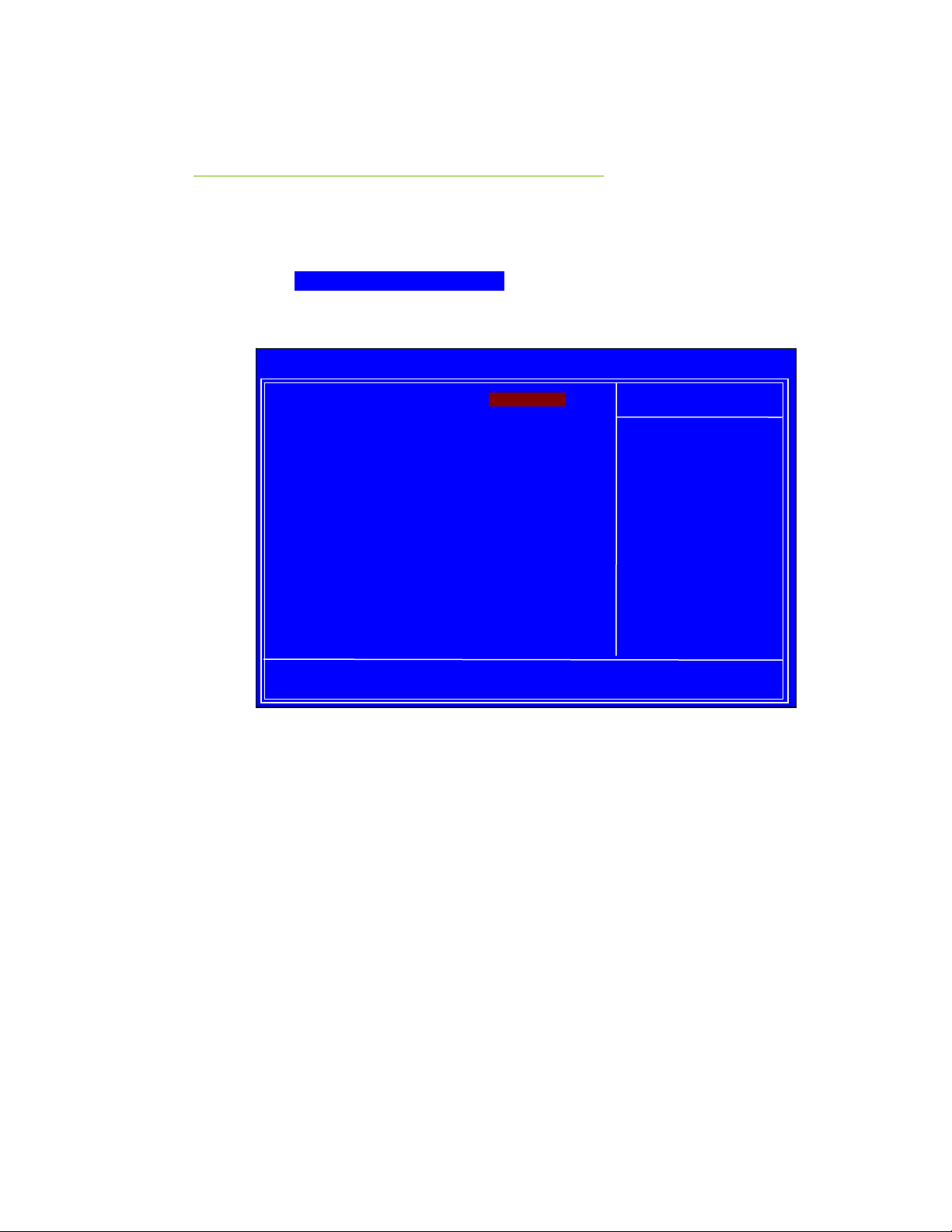
Advanced Chipset Features
Menu
Select Advanced Chipset Features from the CMOS Setup Utility menu and
Enter to display the functions of the Advanced Chipset Functions menu.
press
Phoenix – AwardBIOS CMOS Setup Utility
Advanced Chipset Features
` Spread Spectrum Control [Press Enter]
Init Display First [onboard]
Hybrid SLI [Auto]
Display Detection [Enabled]
x Onboard GPU [Always Enable]
Frame Buffer Size [256M]
HPET Support [Enabled]
Retrain PCIE dev to Gen2 [Enabled]
System BIOS Cacheable [Enabled]
:Move Enter:Select +/-/PU/PD:Value F10:Save ESC:Exit F1:General Help
F5:Previous Values F6:Fail-Safe Defaults F7:O
Figure 6. Advanced Chipset Features
Item Help
Main Level `
timized Defaults
39
EVGA
Page 50

Spread Spectrum Control
Press Enter to display the Spread Spectrum Control menu.
CPU Spread Spectrum [Disabled]
SATA Spread Spectrum [Disabled]
PCIE Spread Spectrum [Disabled]
iGPU Spread Spectrum [Disabled]
CPU Spread Spectrum
This option reduces the EMI generated by the CPU. Options are Disabled
and Enabled.
SATA Spread Spectrum
This option reduces the EMI generated by the S-ATA. Options are Disabled
and Triangular Down.
PCIE Spread Spectrum
This option reduces the EMI generated by the PCI-E. Options are Disabled
and Triangular Down.
Init Display First
Hybrid SLI
EVGA
40
iGPU Spread Spectrum
This option reduces the EMI generated by the iGPU. Options are Disabled,
1.00% Tri-Center, 2.00% Tri-Center and [3.00% Tri-Center].
This item is used to select the display device priority. The options are onboard,
PCI Slot and PCIEx. If you use Hybird SLI card, the PCI Slot option not
appear.
This item allows you set the Hybrid SLI function if you install a Hybrid SLI
card. The options are Auto and Disabled.
Page 51

Configuring the BIOS
Display Detection
This item enabling will cause System BIOS to search for monitor connected if
boot prefer (BGPU) does not have monitor connected. The options are
Enabled and Disabled
Onbaord GPU
This item allows you to set the onboard GPU. Select the [Enable If No
Ext GPU]
graphics card. Select the
GPU.
to enable the onboard GPU, if the system no detects any external
Frame Buffer Size
When you set the iGPU Frame Buffer Control item to [Manual] then allows
you to set frame buffer size for onboard GPU. The options are 16M, 32M,
64M, 128M, 256M, 512M and Disabled. If you install a Hybrid SLI card, the
options are 256M and 512M.
[Always Enable] to always enable the onboard
HPET Support
This function allows you to enable or disable the High Precision Even Timer
(HPET). When Enabled, HPET is used as the timing hardware for multimedia
and other time-sensitive application. When HPET is Disabled, the APIC timer
is used.
Retrain PCIE dev to Gen2
By default all capable devices populated in PCIE slots will be retrained to Gen2
speed. This can be disabled (to force Gen1 only). The options are Disabled and
Enabled.
41
EVGA
Page 52

System BIOS Cacheable
This function allows you to enable or disable caching the system BIOS.
EVGA
42
Page 53
Configuring the BIOS
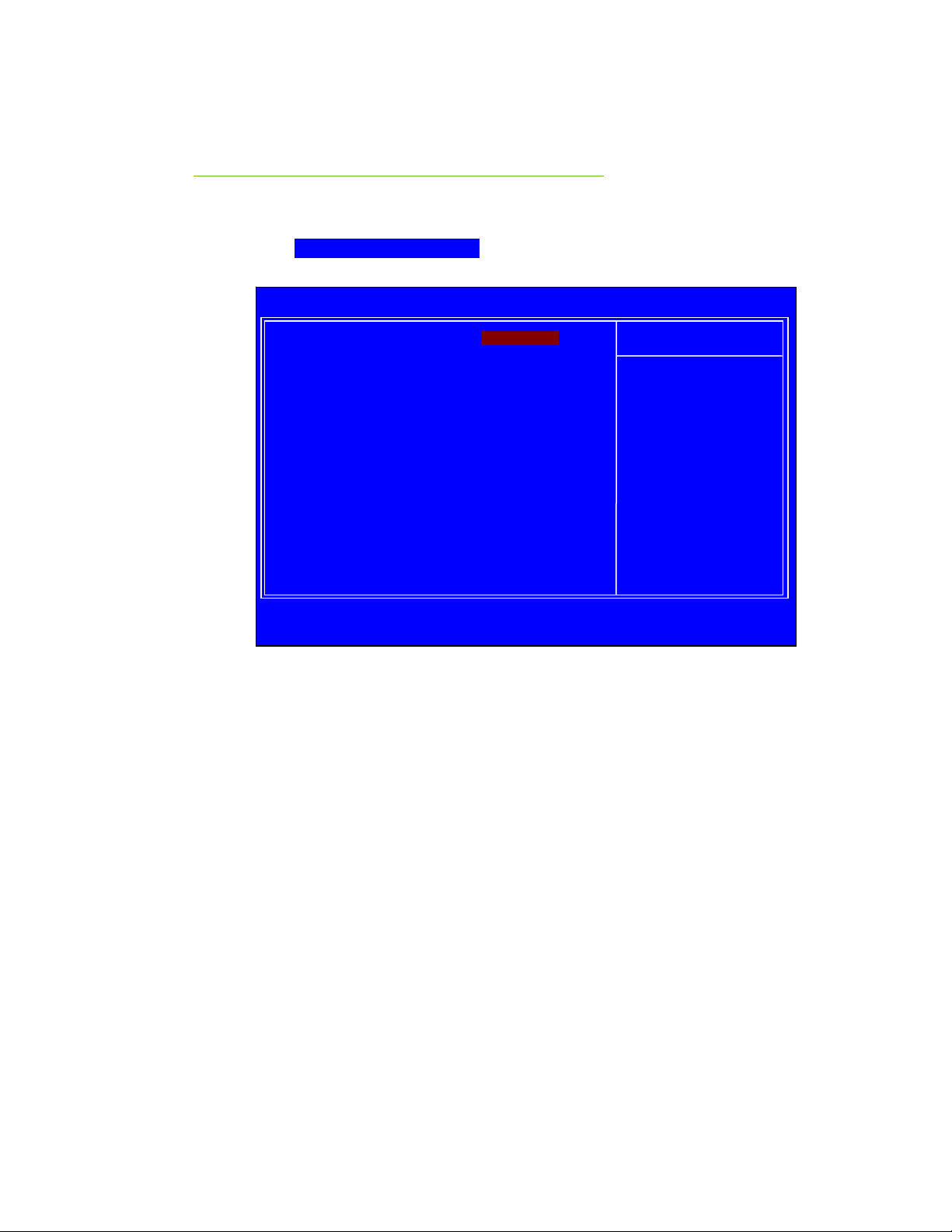
Integrated Peripherals Menu
Select Integrated Peripherals from the CMOS Setup Utility menu and
Enter to display the Integrated Peripherals menu.
press
Phoenix – AwardBIOS CMOS Setup Utility
` Storage Config [Press Enter]
` Onbard Devices [Press Enter]
` Legacy Devices [Press Enter]
` USB Device Setting [Press Enter]
:Move Enter:Select +/-/PU/PD:Value F10:Save ESC:Exit F1:General Help
Integrated Peripherals
-
Figure 7. Integrated Peripherals Menu
Item Help
Main Level `
43
EVGA
Page 54

Storage Config
Press Enter to display the Storage Config menu.
DMA transfer access [Enabled]
Prefetch Mode [Enabled]
HDD Block Mode [Enabled]
SATA Controller [Enabled]
SATA Operation Mode [IDE]
SATA SALP Features [OFF]
JMB363 ATA Controller [Enabled]
JMB363 Mode [IDE]
DMA transfer access
Use this function to enable or disable DMA transfer access.
Prefetch Mode
Use this function to enable or disable the
HDD Block Mode
Using this function on the Integrated Peripherals menu allows your hard drive
needs to support block mode. Select
optimal number of block read/writes per sector the drive can support. Select
[Disabled] if your drive does not support block mode.
Prefetch mode.
[Enabled] to automatically detect the
EVGA
44
SATA Controller
This function allows you to enable specific SATA controllers, enable all
controllers, or disable all controllers.
SATA Operation Mode
This is allows you set the onboard Serial SATA mode.
¾ IDE: Use the Serial ATA hard disk drivers as Parallel ATA storage
devices.
¾ RAID: Create a RAID 0, 1, 0+1, 5 and JBOD configuration.
¾ AHCI: Use the AHCI (Advanced Host Controller Interface) to enables
advanced SATA features for improved performance with NCQ and
Hot-plug features
¾ Linux AHCI: Use the function for Linux AHCI.
Page 55

Configuring the BIOS
[
]
p
SATA SALP Features
This item allows you select the SATA SALP (Aggressive Link Power
Management) status. The options are OFF, Partial, Slumber.
JMB363 ATA Controller
This function allows you to enable SATA controllers by JMicron JMB363
supported. The options are Enabled and Disabled.
JMB363 Mode
This is allows you set the Serial SATA mode by JMicron JMB363. The
options are RAID, IDE and AHCI.
Onboard Devices
Press Enter to display the Onboard Devices menu.
HD Audio [INT Codec + EXT Codec]
MAC Lan [Auto]
P80 Show CPU Tem
erature [Enabled]
HD Audio
This item allows you to enable or disable the hard disk audio function.
Options are Disabled, Internal Codec, External Codec, INT Codec + EXT
Codec
MAC Lan
Use this function to set the MAC LAN to
[Auto] or disable this function.
P80 Show CPU Temperature
When this function is enabled the Post Port LED will display the CPU’s
current temperature. Options are Enabled and Disabled.
Legacy Devices
Press Enter to display the Legacy Devices menu.
Onboard FDC Controller [Enabled]
Onboard Serial Port 1
45
3F8/IRQ4
EVGA
Page 56

Onboard FDC Controller
Select “Enabled” if you wish to use onboard floppy disk controller (FDC). If
you install an external FDC or the system has no floppy drive, select
“Disabled “in this field.
Onboard Serial Port 1
Select an address and corresponding interrupt for the first serial port. Options
are [3F8/IRQ4], [2E8/IRQ3], [3E8/IRQ4], [Auto], and [Disabled].
USB Device Setting
Press Enter to display the USB Device Setting menu.
USB 1.0 Controller [Enabled]
USB 2.0 Controller [Enabled]
USB Operation Mode [High Speed]
USB Keyboard Function [Enabled]
USB Mouse Function [Enabled]
USB Storage Function [Enabled]
USB 1.0 Controller
Use this function to enable the USB 1.0 controller.
EVGA
46
USB 2.0 Controller
Use this function to enable the USB 2.0 (EHCI) controller.
USB Operation Mode
Select the USB Operation Mode for USB device supports transfer rates.
Options are Full/Low Speed and High Speed (480 Mbps).
USB Keyboard Function
Use this function to enable or disable support for USB keyboard under DOS.
USB Mouse Function
Use this function to enable or disable support for USB Mouse under DOS.
USB Storage Function
Use this function to enable or disable legacy support of USB Mass Storage.
Page 57

Power Management Setup
Menu
Select Power Management Setup from the CMOS Setup Utility menu and
Enter to display the Power Management Setup menu.
press
Phoenix – AwardBIOS CMOS Setup Utility
Power Management Setup
ACPI function [Enabled]
APCI Suspend Type [S1&S3]
Soft-Off by PBTN [Instant-Off]
WOL(PME#) From Soft-Off [Disabled]
S5 Resume by USB [Disabled]
Power-on by Alarm [Disabled]
x Day of Month Alarm 0
x Time (hh:mm:ss) Alarm 0 : 0 : 0
POWER ON Function [Disabled]
Hot Key Power On [Ctrl-F1]
PWRON After PWR-Fail [Off]
:Move Enter:Select +/-/PU/PD:Value F10:Save ESC:Exit F1:General Help
Figure 8. Power Management Setup Menu
ACPI Function
This function allows you to enable or disable the ACPI function.
Item Help
Main Level `
-
EVGA
47
Page 58

ACPI Suspend Type
This function allows you to select an ACPI Suspend Type. Types to select from
[S1&S3], [S1(POS)], and [S3(STR)].
are
Soft-Off by PBNT
This function allows you to set Soft-Off by PBNT to [Instant-Off] or
[Delay 4 Sec].
WOL(PME#) From Soft-Off
This function allows you to enable or disable WOL(PME#) from soft-off.
S5 Resume by USB
This function allows a USB device to wake-up the system from Soft-off state.
Power On by Alarm
POWER ON Function
EVGA
48
This function allows you to enable or disable the Power-on by alarm function.
[Disable] to prevent power-on by alarm. When set to [Enable], you
Set to
can manually put in the day of the month and the time of the alarm.
Power-on by Alarm [Disabled]
Day of Month Alarm [0]
Time (hh:mm:ss) Alarm [0 : 0 : 0]
To enter a day or time, use the
numbers or enter the number using the keyboard number or the
This function allows you to define the power-on function by the key press
activity. Options for this function are:
Page Up and Page Down keys to scroll through
+ and – keys.
Page 59

Configuring the BIOS
Disabled
Mouse
Keyboard
Both (Keyboard and Mouse)
Hot Key Power On
Use this function with the above “POWER ON Function” to set a combination
of keys that can be used to power on the system. Options for this function are:
Ctrl-Esc
Ctrl-F1
Ctrl-Space
Anykey
PWRON After PWR-Fail
This function enables your computer to automatically restart or return to its last
operating status after power returns from a power failure.
Off: The system stays off after a power failure.
On: The system stays on after a power failure
49
EVGA
Page 60

PnP/PCI Configuration Menu
Select PnP/PCI Configuration from the CMOS Setup Utility menu and press
Enter to display the PnP/PCI Configuration menu.
Phoenix – AwardBIOS CMOS Setup Utility
PnP/PCI Configuration
Resources Controlled By [Auto(ESCD)]
x IRQ Resources Press Enter
PCI/VGA Palette Snoop [Disabled]
** PCI Express relative items **
Maximum Payload Size [4096]
:Move Enter:Select +/-/PU/PD:Value F10:Save ESC:Exit F1:General Help
-
Figure 9. PnP/PCI Configuration Menu
Item Help
Main Level `
EVGA
50
Page 61

Resources Controlled By
Q Resources
[Press
]
This function on the PnP/PCI Configuration menu allows you to define if the
BIOS can automatically configure all the boot and plug-and-play compatible
devices or if you can manually select IRQ, DMA, and memory base address
fields. Select
these fields. If you select
Resources
Resources Controlled By [Auto(ESCD)]
x IRQ Resources Press Enter
Resources Controlled By [Manual)]
IR
[Auto(ESCD)] if you want the BIOS to automatically populate
[Manual] so you can assign the resources, IRQ
is enabled for input.
IRQ Resources
To enable this field for input, set Resources Controlled By to
[Manual]. With this field enabled, press Enter to see options.
Enter
IRQ-5 assigned to [PCI Device]
IRQ-7 assigned to [PCI Device]
IRQ-9 assigned to [PCI Device]
IRQ-10 assigned to [PCI Device]
IRQ-11 assigned to [PCI Device]
IRQ-14 assigned to [PCI Device]
Use Legacy ISA for devices compliant with the original PC AT Bus
specification. Use PCI/ISA PnP for devices compliant with the plug-and-play
standard, whether designed for PCI or ISA Bus architecture.
PCI/VGA Palette Snoop
This function on the PnP/PCI Configuration menu allows you to enable or
disable the Palette Snoop function.
EVGA
51
Page 62

Maximum Payload Size
This function on the PnP/PCI Configuration menu allows you to set the
maximum TLP payload size (in bytes) for the PCI Express devices. Use the
Page Up and Page Down keys to scroll through sizes or enter the number using
the keyboard numbers or use the
sizes.
+ and – keys to go up and down the list of
EVGA
52
Page 63
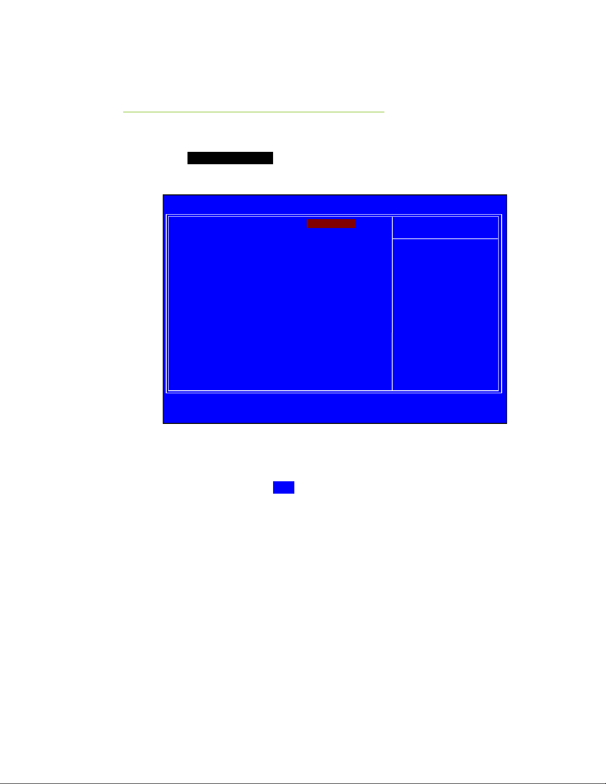
Configuring the BIOS
PC Health Status Menu
Select PC Health status from the CMOS Setup Utility menu and press Enter
to display the PC Health Status menu.
Phoenix – AwardBIOS CMOS Setup Utility
` SmartFan Function [Press Enter]
+5V 4.96V
DIMM(V) 1.89V
5VSB 4.96V
+12V 12.14V
Chipset(V) 1.09V
CPU(V) 1.21V
3VSB 3.37V
Voltage Battery 3.12V
CPU Temperature 34
System Temperature 28
CPU Fan Speed 3054 RPM
Power Fan Speed 0 RPM
System Fan Speed 0 RPM
:Move Enter:Select +/-/PU/PD:Value F10:Save ESC:Exit F1:General Help
PC Health Status
o
C
o
C
Figure 2. PC Health Status Menu
Item Help
Main Level `
All of the values shown in Blue are dynamic and change as the speed and
voltages of the various components change with system usage.
53
EVGA
Page 64

SmartFan Function
Press Enter to display the SmartFan Function menu.
Smart CPUFan Function [Full Speed]
CPU Temperature 34ºC
CPU Fan Speed 3080 RPM
x SmartFan Duty Cycle 90%
Full FAN Speed [100%]
x Temp H-Full FAN Threshold 60ºC/ 140ºF
x Fast FAN Speed 75%
x Temp M-Quiet FAN Threshold 40ºC/ 104ºF
x Quiet FAN Speed 50%
x Temp L-Start/Stop FAN 20ºC/ 68ºF
Stop FAN Speed [30%]
Use this menu to control the speed of the various fans on the motherboard.
Full speed fixes fan speed at100% duty cycle. Control the Fan by Duty-Cycle
directly. By Temperature calculates the fan speed according to different
temperature range.
EVGA
54
How effective Smart CPU Fan is will depend on fan design. Most fans have
built-in thermistor and may self adjust its speed. Some fans have very limited
duty cycle range open to fan control.
Page 65
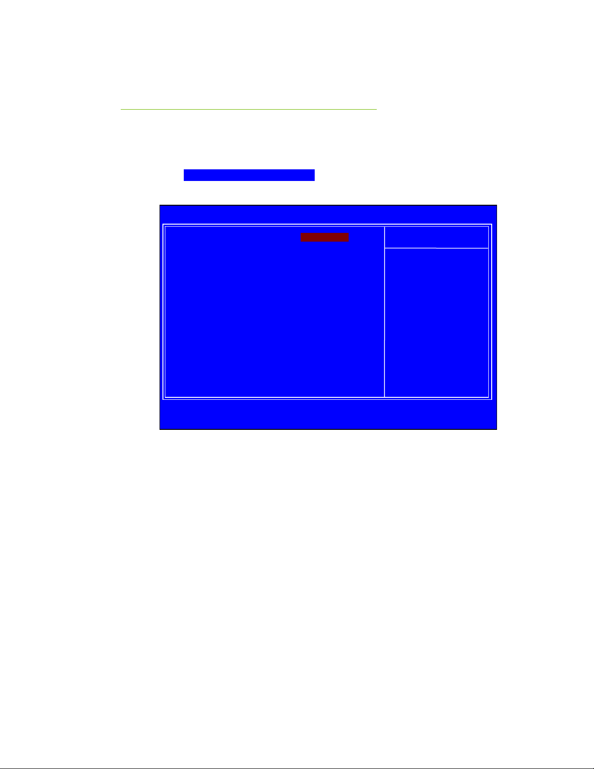
Frequency/Voltage Control
Menu
Select Frequency/Voltage Control from the CMOS Setup Utility menu and
Enter to display the Frequency/Voltage Control menu.
press
Phoenix – AwardBIOS CMOS Setup Utility
Frequency/Voltage Control
` System Clocks [Press Enter]
` FSB & Memory Config [Press Enter]
` System Voltage [Press Enter]
` CPU Feature [Press Enter]
CPU Clock Ratio Unlock [Disabled]
:Move Enter:Select +/-/PU/PD:Value F10:Save ESC:Exit F1:General Help
-
Main Level `
Figure 3. Frequency/Voltage Control Menu
Item Help
EVGA
55
Page 66
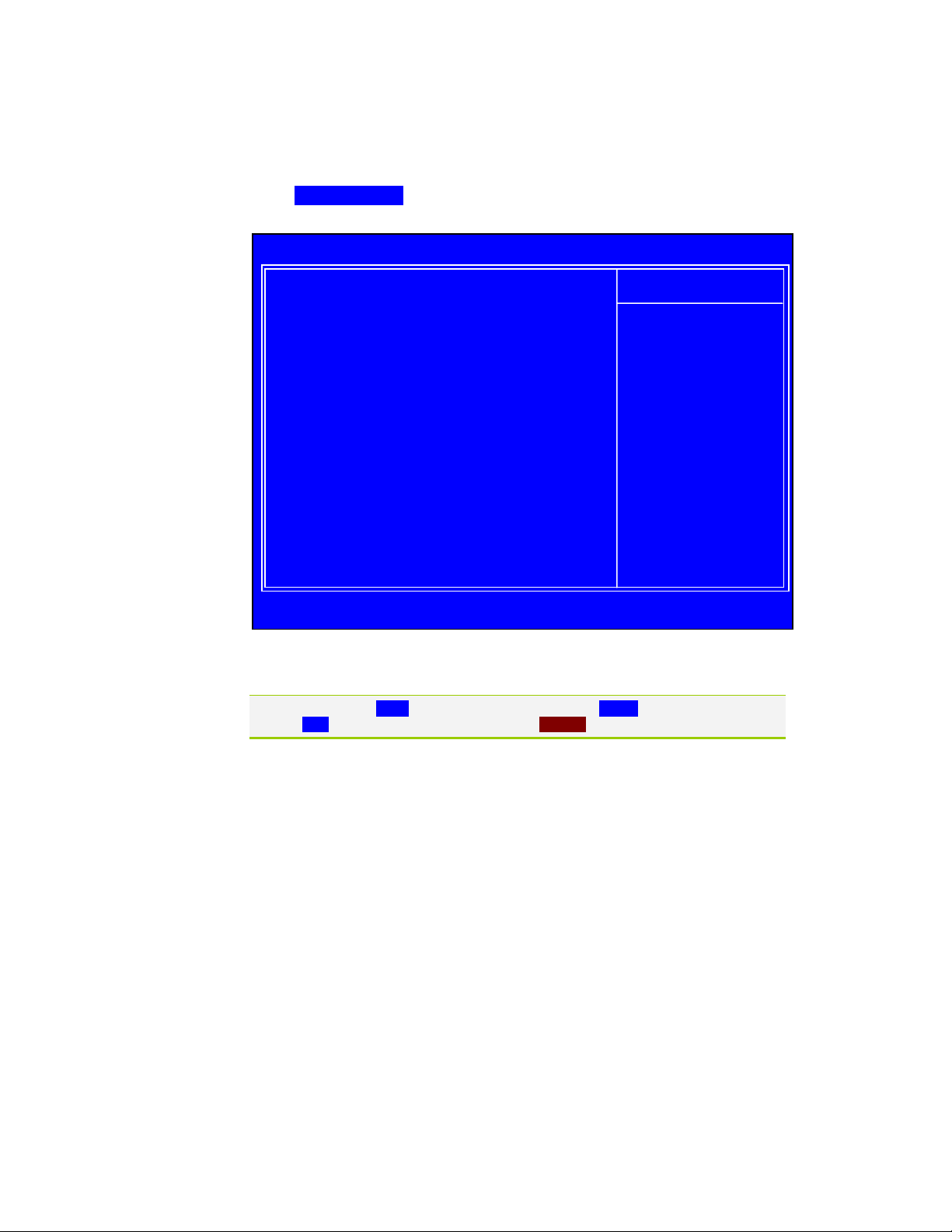
System Clocks
p
Select System Clocks from the Frequency/Voltage Control menu and press
Enter to display the System Clocks menu.
Parameters Settings Current Value
**Frequency Settings**
Current CPU Freq, MHz 3000.0 3000.0
FSB Clock, MHz 1333.3 1333.3
Phoenix – AwardBIOS CMOS Setup Utility
System Clocks
Item Help
Main Level `
:Move Enter:Select +/-/PU/PD:Value F10:Save ESC:Exit F1:General Help
F5:Previous Values F6:Fail-Safe Defaults F7:O
timized Defaults
Figure 4. System Clocks Menu
Note that all data in white is for information only, data in yellow is changeable, data in
blue is non-changeable, and data in a red box is highlighted for selection.
Frequency Settings
Current CPU Freq, MHz
This value is set by the CPU Multiplier (value cannot be changed by the user).
FSB Clock. MHz
This value is set by the system (value cannot be changed by the user). To
EVGA
56
Page 67
Configuring the BIOS
p
change the FSB memory, and memory timing, go to the FSB & Memory
screen.
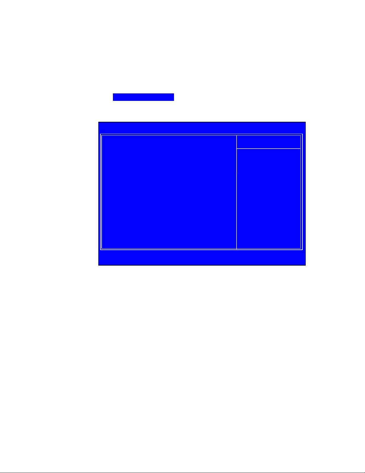
FSB & Memory Config
Select FSB & Memory Config from the Frequency/Voltage Control menu and
press
Enter to display the FSB & Memory Config menu. This menu provides
the means to set FSB memory, and memory timing.
Phoenix – AwardBIOS CMOS Setup Utility
FSB & Memory Config
Parameters Settings Current Value
CPU Freq, MHz 3000.0 3000.0
CPU Multiplier 9X 9X
FSB – Memory Clock Mode [Auto]
x FSB – menory Ratio Auto
x FSB (QDR), MHz Auto 1333.3
Actual FSB (QDR), MHz 1333.3
x MEM (DDR), MHz Auto 800.0
Actual MEM (DDR), MHz 800.0
` Memory Timing Setting [Press Enter]
:Move Enter:Select +/-/PU/PD:Value F10:Save ESC:Exit F1:General Help
F5:Previous Values F6:Fail-Safe Defaults F7:O
Item Help
Main Level ``
“Auto” realizes the
complete optimized
memory settings
Optimized memory
settings by allowing
X% CPU overclocking
CPU overclocking may
require manual
overvoltaging of the
CPU to improve system
stability
timized Defaults
Figure 5. FSB & Memory Config Menu
FSB - Memory Clock Mode
Use the Page Up and Page Down keys to scroll through the FSB and
Memory Clock Mode options. The options are:
57
EVGA
Page 68

¾ Auto
This is the optimal setting since it sets the FSB and memory speeds
automatically.
¾ Linked
When Link is selected,
FSB-Memory Ratio and FSB (QDR), MHz
are changed to editable and the FSB speed can be entered manually. As
the FSB speed is changed,
CPU Freq, MHz changes proportionally.
FSB – Memory Clock Mode [Linked]
FSB – Memory Ratio [Auto]
FSB (QDR), MHz [1067] 1066.7
Actual FSB (QDR), MHz 1066.7
x MEM (DDR), MHz Auto 800.6
Actual MEM (DDR), MHz 800.0
¾ Unlinked
When Unlink is selected,
FSB (QDR), MHz and MEM (DDR), MHz
are changed to editable and the FSB and memory speeds can be entered
manually. As the FSB speed is changed,
CPU Freq, MHz changes
proportionally.
FSB – Memory Clock Mode [Unlinked]
FSB – Memory Ratio [Auto]
FSB (QDR), MHz [1067] 1066.7
Actual FSB (QDR), MHz 1066.7
MEM (DDR), MHz [1067] 800.6
Actual MEM (DDR), MHz 800.0
FSB (QDR), MHz
Use the
or type in a new value. Note that the
+ or – keys to scroll through new values for the CPU FSB frequency
Actual FSB (QDR) reflects the actual
frequency that takes effect on a reboot.
EVGA
58
MEM (DDR), MHz
Use the
or type in a new value. Note that the
+ or – keys to scroll through new values for the memory frequency
Actual MEM (DDR) reflects the actual
frequency that takes effect when the system reboots.
Page 69
Configuring the BIOS
p
Memory Timing Setting
Press Enter to display the Memory Timing Setting menu. Use this menu to
set optimal timings or to manually enter timings.
Phoenix – AwardBIOS CMOS Setup Utility
Memory Timing Setting
Parameters Settings Current Value
Memory Timing Setting [Optimal]
x tCL (CAS Latency) Auto(7) 7
x tRCD Auto(7) 7
x tRP Auto(7) 7
x tRAS Auto(20) 20
x Command Per Clock (CMD) Auto(1T) 1T
** Advanced Memory Settings **
x tRRD Auto(4) 4
x tRC Auto(27) 27
x tWR Auto(10) 10
x tWTR Auto(14) 14
x tREF Auto 7.8uS
:Move Enter:Select +/-/PU/PD:Value F10:Save ESC:Exit F1:General Help
F5:Previous Values F6:Fail-Safe Defaults F7:O
Main Level ``
Select [Expert] to
enter timings manually
timized Defaults
¾ Optimal
Use the
Page Up and Page Down keys to select Optimal. Optimal
prohibits you from manually setting any timing. All timing is set for
optimal performance.
Item Help
59
EVGA
Page 70

¾ Expert
Use the
Page Up and Page Down keys to select Expert. When Expert is
selected, all timing categories are enabled for manual input. Note that you
should set the value to Optimal to use the manufacturers’ recommended
values.
Parameters Settings Current Value
Memory Timing Setting [Expert]
tCL (CAS Latency) [Auto(7)] 7
tRCD [Auto(7)] 7
tRP [Auto(7)] 7
tRAS [Auto(20)] 20
Command Per Clock (CMD) [Auto(1T)] 1T
** Advanced Memory Settings **
tRRD [Auto(4)] 4
tRC [Auto(27)] 27
tWR [Auto(10)] 10
tWTR [Auto(14)] 14
tREF [Auto] 7.8uS
¾
tCL: CAS# latency (options are Auto and 1 through 7).
tRCD: RAS#-to-CAS# Delay for Read/Write commands to the
¾
same bank (options are Auto and 1 through 7).
¾
tRP: Row Precharge time. This is the Precharge-to-Active or Auto-
to-Refresh of the same bank (options are Auto and 1 through 7).
¾
tRAS: This is the minimum RAS# active time (options are Auto and
1 through 31).
¾
Command Per Clock: This is the command timing setting on a per
clock unit basis (options are Auto, 1 Clock and 2 Clock).
¾
tRRD: RAS#-to-RAS# delay of different banks (options are Auto
and 1 through 15).
¾
tRC: RAS#-to-RAS# or auto refresh time of the same bank (options
are Auto and 1 through 31).
¾
tWR: The Write recovery time (options are Auto and 2 through 6).
¾
tWTR: This is the minimum write-to-read delay with the same chip
selected (options are Auto and 1 through 15).
¾
tREF: This is the DRAM refresh rate (options are Auto, 7.8uS, and
3.9uS)..
EVGA
60
Page 71
Configuring the BIOS
p
System Voltages
Select System Voltages from the Frequency/Voltage Control menu and press
Enter to display the System Voltages menu.
Phoenix – AwardBIOS CMOS Setup Utility
System Voltages
Parameters Settings Current Value
CPU Core [Auto] 1.22500V
CPU FSB [Auto] 1.20V
Chipset Voltage [Auto] 1.1V
Memory [Auto] 1.800V
CPU PLL [Auto] 1.5V
NF200 Voltage Level [Auto] 1.20V
GTLVREF Lane 0 [Auto] +00mv
GTLVREF Lane 1 [Auto] +00mv
GTLVREF Lane 2 [Auto] +00mv
GTLVREF Lane 3 [Auto] +00mv
:Move Enter:Select +/-/PU/PD:Value F10:Save ESC:Exit F1:General Help
F5:Previous Values F6:Fail-Safe Defaults F7:O
Main Level ``
Voltage level for CPU
Core (CPU VID)
timized Defaults
Figure 6. System Voltages Menu
CPU Core
Use the
[Auto] to automatically set the voltage level for the CPU Core.
Page Up and Page Down keys to scroll through the voltages or select
Item Help
61
EVGA
Page 72

CPU FSB
Use the
[Auto] to automatically set the voltage level for the CPU FSB.
Page Up and Page Down keys to scroll through the voltages or select
Chipset Voltage
This function defines the core voltage level for the NVIDIA nForce SPP
chip. Use the
1.3V, 1.4V) or select
Page Up and Page Down keys to select a voltage (1.1, 1.2V,
[Auto]to automatically set the voltage.
Memory
This function defines the voltage level for the DRAM. Use the
Page Down keys to select a voltage or select [Auto] to automatically set the
Page Up and
voltage.
CPU PLL
This function defines the voltage level for the CPU PLL. Use the
Page Up
and Page Down keys to select a voltage or select [Auto]to automatically set
the voltage.
GTLVREF Lane 0
This function defines the voltage level for GTLVREF Lane 0. Use the
Up
and Page Down keys to select a voltage or select [Auto]to automatically
set the voltage.
Page
GTLVREF Lane 1
This function defines the voltage level for GTLVREF Lane 1. Use the
Up
and Page Down keys to select a voltage or select [Auto]to automatically
Page
set the voltage.
GTLVREF Lane 2
This function defines the voltage level for GTLVREF Lane 2. Use the
Up
and Page Down keys to select a voltage or select [Auto]to automatically
Page
set the voltage.
GTLVREF Lane 3
This function defines the voltage level for GTLVREF Lane 3. Use the
Up
and Page Down keys to select a voltage or select [Auto]to automatically
Page
set the voltage.
EVGA
62
Page 73

CPU Feature
Press Enter to display the CPU Feature menu.
Thermal Management [Disabled]
Intel SpeedStep [Disabled]
x PPM Mode Native
Limit CPUID MaxVal [Disabled]
C1E Function [Auto]
Execute Disable Bit [Enabled]
Virtualization Technology [Enabled]
Thermal Management
Use this function to enable or disable TM1 and TM2 support. Options are:
¾ Disable
Disable support for TM1 and TM2.
¾ TM1 Only
The CPU is thermally throttled by cutting active processor clock cycles.
¾ TM2 Only
Thermal throttling is achieved by reducing the CPU multiplier and CPU
core voltage.
¾ TM1 & TM2
Enables support for both TM1 and TM2.
Intel SpeedStep
This item select enabled, CPU clock speed and CPU core voltage are adjusted
dynamically based on the CPU load.
PPM Mode
There are two mode options that can be selected. The Native mode is for
fully support ACPI OS (ex. WINXP, VISTA...), SMM mode is for legacy OS
(ex. WIN2K…).
Limit CPUID MaxVal
Use this function to enable the set limit of the CPUID MaxVal to 3. Set to
Disable for Win XP.
EVGA
63
Page 74

C1E Function
Enabled, this function reduces the CPU power consumption when the CPU
is idle. Idle occurs when the operating system issues a halt instruction.
Execute Disable Bit
When this function is disabled, it forces the XD feature flag to always return
to zero (0).
Virtualization Technology
When this function is enabled, it allows a VMM to utilize the additional
hardware capabilities provided by Intel Virtualization Technology.
CPU Clock Ratio Unlock
Select Enabled, if you install a CPU that supports this feature. The following
item become available to select a multiplier to set the CPU frequency. If
your CPU multiplier is locked this option will be unavailable.
EVGA
64
Page 75

Configuring the BIOS
Installing Drivers and
Software
It is important to remember that before installing the driver CD that is shipped in the
kit, you need to load your operating system. The motherboard supports
Windows XP 32bit and 64bit and is Vista-capable.
The kit comes with a CD that contains utility drivers and additional NVIDIA
software.
The CD that has been shipped with your EVGA motherboard contains the
following software and drivers:
NVIDIA nForce motherboard drivers
Audio drivers
RAID Drivers
JMicron Drivers
Adobe Acrobat Reader
User’s Manual
Drivers Installation
1. Insert the EVGA nForce 730i installation CD for the motherboard
included in the kit.
2. The CD will autorun, install the drivers and utilities listed on the install
screen.
If it does not run, go to My Computer and click on the CD to open.
65
EVGA
Page 76

ACPI - Advanced Configuration and Power Interface
AFR – Alternate Frame Rendering
APIC - Advanced Programmable Interrupt Controller
BIOS - Basic Input Output System
CD-ROM - Compact Disc Read-Only Memory
CMOS - Complementary Metal-Oxide Semiconductor
CPU – Central Processing Unit
D-ICE – Dry Ice Cooling
DDR2 - Double Data Rate 2
DDR3 - Double Data Rate 3
DIMM - Dual In-line Memory Module
DRAM - Dynamic random access memory
DVD - Digital Versatile Disc
DVI – Digital Video Interface
FDC - Floppy Disk Controller
FSB – Front Side Bus
FTW – For The Win!
GHz – Gigahertz
GPU – Graphics Processing Unit
HDD - Hard Disk Drive
HDMI - High-Definition Multimedia Interface
HDR – High Dynamic Range Lighting
HPET - High Precision Event Timer
HSF - Heat Sink Fan
I/O - Input/Output
IDE - Integrated Drive Electronics
IEEE - Institute of Electrical and Electronics Engineers
IGP - Integrated Graphics Processors
IRQ - Interrupt Request
JBOD - Just a Bunch of Disks
JEDEC - Joint Electron Device Engineering Council
LAN - Local Area Network
LCD - Liquid Crystal Display
LGA – Land Grid Array
LN2 – Liquid Nitrogen Cooling
EVGA
66
Page 77

MAC - Media Access Control
MCP - Media and Communications Processor
MHz - Megahertz
NB - Northbridge
NCQ - Native Command Queuing
NIC - Network Interface Card
NTFS - New Technology File System
OEM - Original Equipment Manufacturer
PATA - Parallel Advanced Technology Attachment
PCB - Printed Circuit Board
PCI - Peripheral Component Interconnect
PCIe - Peripheral Component Interconnect Express
PCI-x - Peripheral Component Interconnect Extended
POST – Power on Self Test
PWM – Pulse Width Modulation
QDR - Quad Data Rate
RAID - Redundant Array of Inexpensive Disks
RGB - Red Green Blue
SATA - Serial Advanced Technology Attachment
SB - Southbridge
SCSI - Small Computer System Interface
SFR – Split Frame Rendering
SLI - Scalable Link Interface
SPD - Serial Presence Detect
SPDIF - Sony/Philips Digital Interconnect Format
SPP - System Platform Processors
TCP/IP - Transmission Control Protocol/Internet Protocol
USB - Universal Serial Bus
VDroop - V-core Voltage Drop
VGA - Video Graphics Array
67
EVGA
Page 78
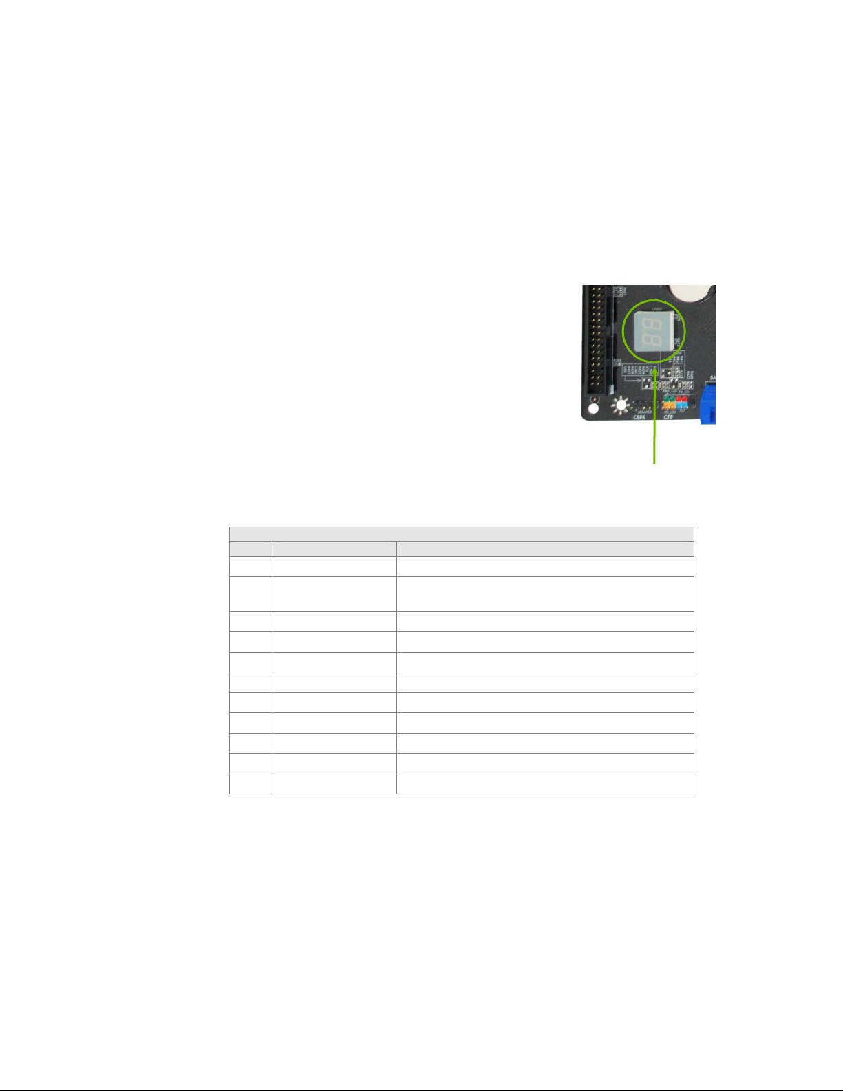
Appendix A
A
POST Codes for the EVGA nForce 730i
Motherboard
This section provides the Award POST Codes (Table 6)
for the EVGA nForce 730i Motherboard during system
boot up.
The POST Codes are displayed on the LED POST
Codereadout located directly onboard the motherboard.
The LED POST Code readout will also display current
CPU temperatures.
Debug LED
Table 3. Award POST Code
ward POST Codes
Code Name Description
01 Reserved
02 Jumps to E000
segment
03 Early SuperIO Init Early Initialized the super IO
04 Reserved
05 Blank video Reset Video controller
06 Reserved
07 Init KBC Keyboard controller init
08 KB test Test the Keyboard
09 Reserved
0A Mouse Init Initialized the mouse
0B Reserved
Execution of POST routines in E000
Page 79

A
ward POST Codes
Code Name Description
0C Reserved
0D Reserved
0E CheckSum Check Check the integrity of the ROM,BIOS and message
0F Reserved
10 Autodetect EEPROM Check Flash type and copy flash write/erase routines
11 Reserved
12 Test CMOS Test and Reset CMOS
13 Reserved
14 Load Chipset Load Chipset Defaults
15 Reserved
16 Init Clock Initialize onboard clock generator
17 Reserved
18 Init CPU CPU ID and initialize L1/L2 cache
19 Reserved
1A Reserved
1B Setup Interrupt
Vector Table
1C CMOS Battery Check Test CMOS and check Battery Fail
1D Early PM Early PM initialization
1E Reserved
1F Re-initial KB Load keyboard matrix
20 Reserved
21 HPM init Init Heuristic Power Management (HPM)
22 Reserved
23 Program chipset Early Programming of chipset registers
24 Init PNP Init PNP
25 Shadow VBIOS Shadow system/video BIOS
26 Clock Gen Init onboard clock generator and sensor
27 Setup BDA Setup BIOS DATA AREA (BDA)
28 Reserved
Initialize first 120 interrupt vectors wi th
SPURIOUS_INT_HDLR and initialize INT 00h-1Fh
according to INT_TBL
69
EVGA
Page 80

A
ward POST Codes
Code Name Description
29 CPU Speed detect Chipset programming and CPU Speed detect
2A Reserved
2B Init video Initialize Video
2C Reserved
2D Video memory test Test Video Memory and display Logos
2E Reserved
2F Reserved
30 Reserved
31 Reserved
32 Reserved
33 Early keyboard reset Early Keyboard Reset
34 Reserved
35 Test DMA Controller 0 Test DMA channel 0
36 Reserved
37 Test DMA Controller 1 Test DMA channel 1
38 Reserved
39 Test DMA Page
Registers
3A Reserved
3B Reserved
3C Test Timer Test 8254 Timer 0 Counter 2.
3D Reserved
3E Test 8259-1 Mask Verify 8259 Channel 1 masked interrupts by
3F Reserved
40 Test 8259-2 Mask Verify 8259 Channel 2 masked interrupts by
41 Reserved
42 Reserved
43 Test Stuck Interrupt Turn off interrupts then verify no 8259's interrupt
44 Reserved
Test DMA Page Registers
alternately turning off and on the interrupt lines.
alternately turning off and on the interrupt lines.
mask register is on. Test 8259 Force an interrupt and
verify the interrupt occurred.
EVGA
70
Page 81

A
ward POST Codes
Code Name Description
45 Reinit serial port Reinitialize Preboot agent serial port
46 Reserved
47 EISA Test If EISA non-volatile memory checksum is good,
execute EISA initialization. If not, execute ISA tests
and clear EISA mode flag.
48 Reserved
49 Size Memory Size base memory from 256K to 640K and exte nd ed
memory above 1MB.
4A Reserved
4B Reserved
4C Reserved
4D Reserved
4E Init APIC Initialize APIC and set MTRR
4F Reserved
50 USB init Initialize USB controller
51 Reserved
52 Memory Test Test all memory of memory above 1MB using Virtual
8086 mode, page mode and clear the memory
53 Reserved
54 Reserved
55 CPU display Detect CPU speed and display CPU vendor specific
version string and turn on all necessary CPU features
56 Reserved
57 PnP Init Display PnP logo and PnP early init
58 Reserved
59 Setup Virus Setup virus protect according to Protect Setup
5A Reserved
5B Awdflash Load If required, will auto load Awdflash.exe in POST
5C Reserved
5D Onboard I/O Init Initializing onboard superIO
5E Reserved
5F Reserved
71
EVGA
Page 82

A
ward POST Codes
Code Name Description
60 Setup enable Display setup message and enable setup functions
61 Reserved
62 Reserved
63 Initialize Mouse Detect if mouse is present, initialize mouse, install
interrupt vectors.
64 Reserved
65 PS2 Mouse special Special treatment to PS2 Mouse port
66 Reserved
67 ACPI init ACPI sub-system initializing
68 Reserved
69 Init Cache Initialize cache controller
6A Reserved
6B Setup Enter setup check and autoconfiguration check up
6C Reserved
6D Initialize Floppy Initialize floppy disk drive
6E Reserved
6F FDD install Install FDD and setup BIOS data area parameters
70 Reserved
71 Reserved
72 Reserved
73 Initialize Hard Drive Initialize hard drive controller
74 Reserved
75 Detect HDD IDE device detection
76 Reserved
77 Detect serial ports Initialize serial ports.
78 Reserved
79 Reserved
7A Detect parallel ports Initialize parallel ports.
7B Reserved
7C HDD Write Protect HDD check for write protection
7D Reserved
7E Reserved
7F POST error check Check POST error and display them and ask for user
EVGA
72
Page 83

A
ward POST Codes
Code Name Description
intervention
80 Reserved
81 Reserved
82 Security Check Ask password security.
83 Write CMOS Write all CMOS values back to RAM and clear screen.
84 Display PNP Display PNP devices
85 USB Final Init Final USB initialization
86 Reserved
87 Reserved
88 Reserved
89 Setup ACPI tables Setup ACPI tables
8A Reserved
8B Option ROM Detect Scan for Option ROMs
8C Reserved
8D Enable Parity Check Enable Parity Check
8E Reserved
8F IRQ12 Enable Enable IRQ12 if mouse present
90 Reserved
91 Reserved
92 Reserved
93 Boot Medium Read Detect and store boot partition head and cylinders
values in RAM
94 Final Init Final init for last micro details before boot
95 NumLock Set NumLock status according to Setup
96 Boot Attempt Set low stack Boot via INT 19h.
C0 Base CPU test Read/Write CPU registers
C1 Memory Presence Base memory detect
C2 Early Memory Board Initialization
C3 Extend Memory Turn on extended memory, cache initialization
C4 Special Display First display initialization
C5 Early Shadow Early shadow enable for fast boot
73
EVGA
Page 84
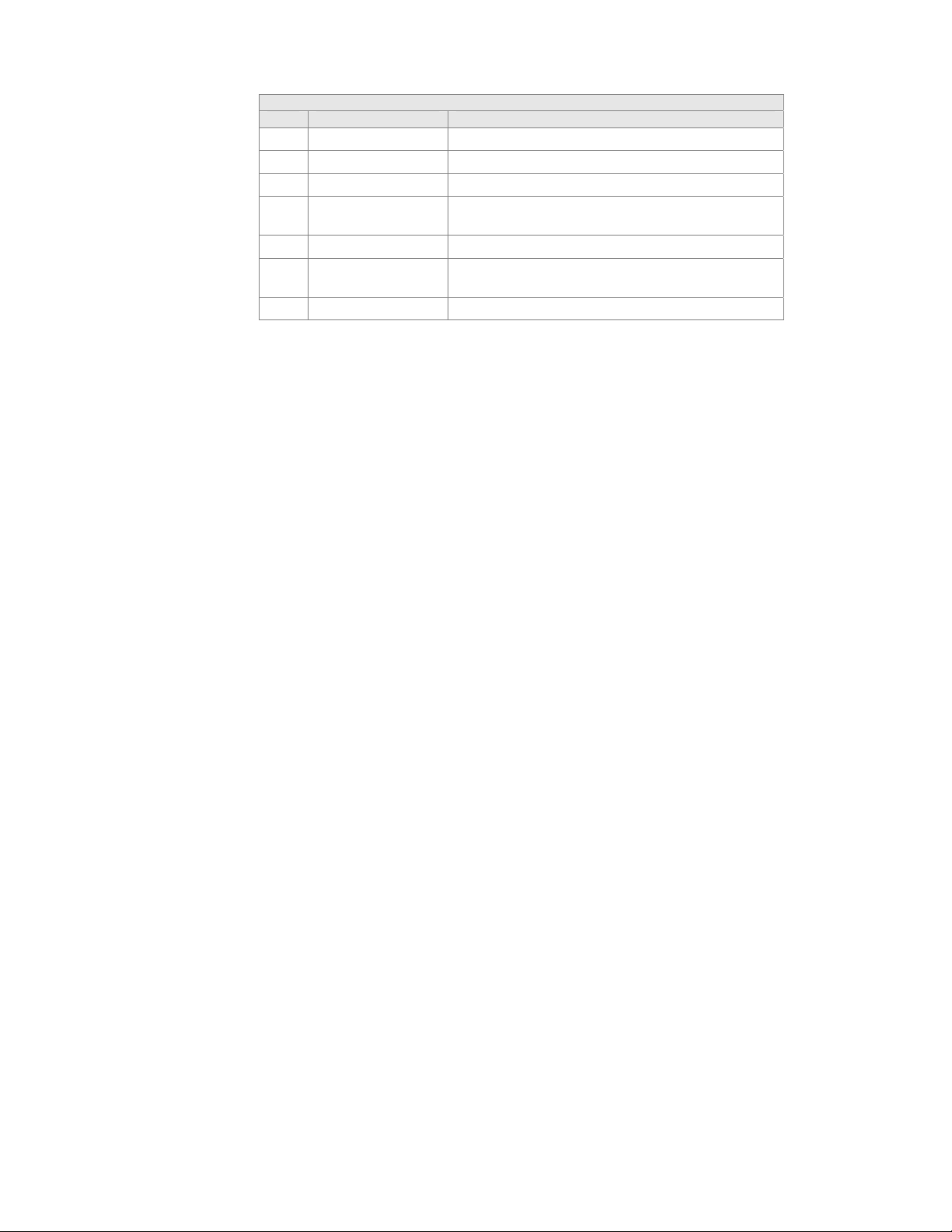
A
ward POST Codes
Code Name Description
C6 Cache presence External cache size detection
CF CMOS Check CMOS checkup
B0 Spurious If interrupt occurs in protected mode.
B1 Unclaimed NMI If unmasked NMI occurs, display Press F1 to disable
NMI, F2 reboot.
BF Program MCP To program chipset from defaults values
E1-
Setup Pages E1- Page 1, E2 - Page 2, etc.
EF
FF Boot
EVGA
74
Page 85

 Loading...