

Page 1
User Manual
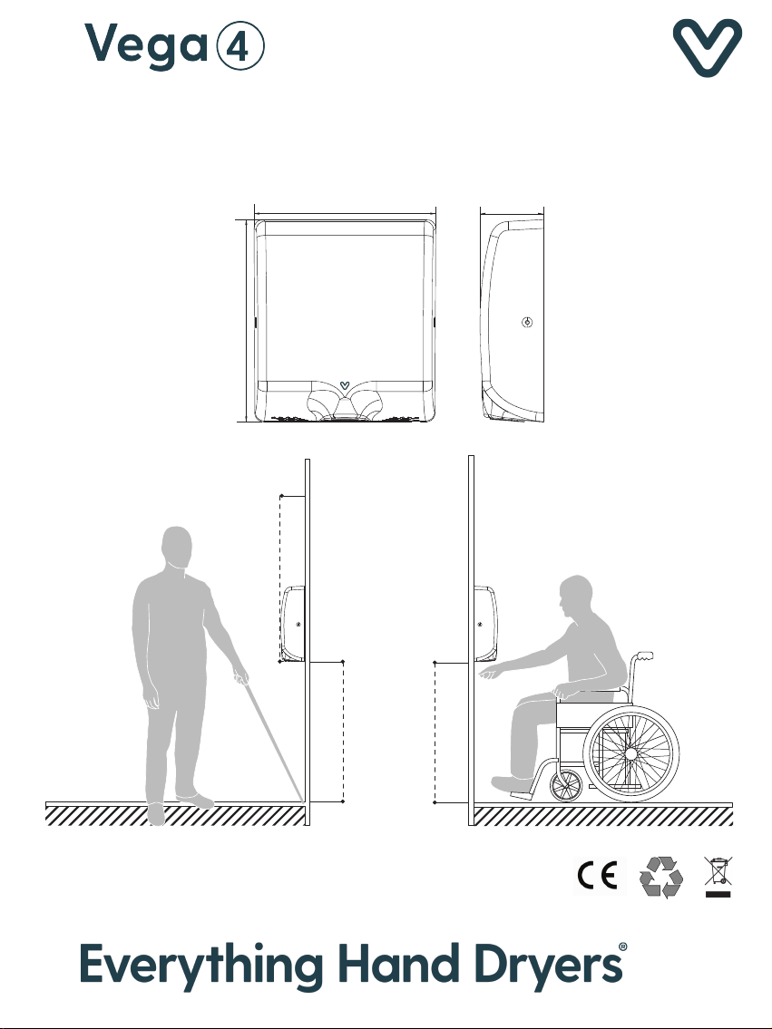
321MM
4"max.
99MM
286MM
(No recessing needed)
99MM
34"min.
86MM
86MM
34"min.
Page 2
1. WARNING
. This product is intended for installation by
a qualified service person.
. Disconnect power at the service breaker
before installing or serving.
. Failure to properly ground unit could result
in severe electrical shock.
. All units must be supplied with a 3-wire
service. The ground wire must be connected
to the dryer’s backplate.
3. SPECIFICATION
Voltage:
Air Temperature:
Air Velocity:
Air Flow:
Drying Time:
Sensor Range:
Protection Level:
Electric Isolation:
Brush Motor:
Noise(at 1M):
Cabinet Material:
220V-240V 50/60Hz,1000W
35℃(D=10CM,Room Temp.=25℃)
100M/S
130M3/H
12S
5-15CM
IPX1
CLASS 1
30000RPM
70dB
Stainless Steel 304
4. INSTALLATION
1.
Installation must be carried out in
accordance with the current edition of
the local wiring regulations code having
jurisdiction. Installation should be
performed only by a qualified electrician.
Place template against wall at desired
2.
height(see mounting height
recommendations) and mark locations
of 4 mounting holes Dia. 8mm(5/16").
Remove and retain 2 side security hex
3.
cover screws and cover. Then mount
the hand dryer base on the wall.
Before replacing cover, there is an
4.
option to run dryer heater on(1000W) or
heater off(600W). The switch is
2. NOTE
Do not install dryer over washbasin.
If the power supply cord is damaged, it must
be replaced by the manufacturer or its
service agent or similar qualified person in
order to avoid a hazard. Means for
disconnection must be incorporated in the
fixed wiring in accordance with the current
wiring regulations.
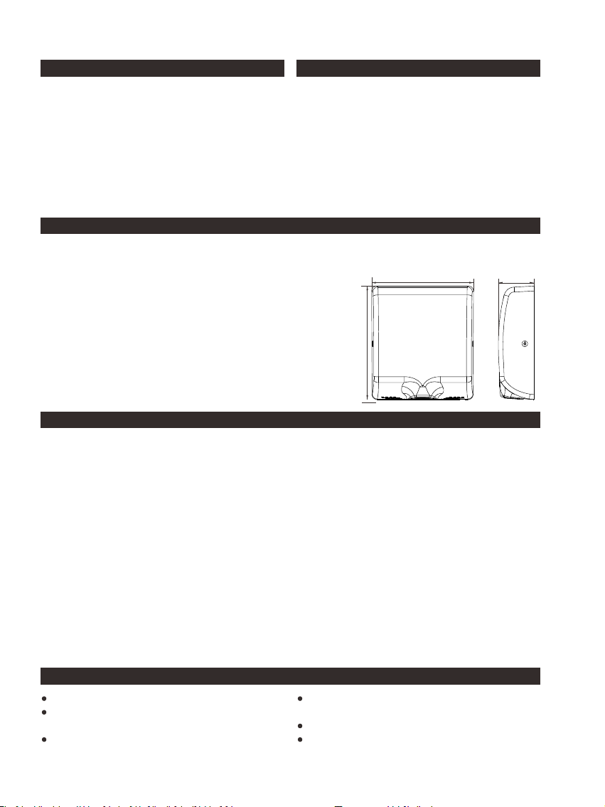
286MM
321MM
clearly marked. Replace cover.
Do not over-tighten screws.
Connect the hand dryer plug to the
5.
power supply.
If hand dryer is supplied in hard wired:
6.
a. Connect the live wire(Coloured
Brown, Red, or Black) to the terminal
block marked “L”.
b. Connect the neutral wire(Coloured
Black, Blue) to the terminal block
marked “N”.
c. Connect the ground wire(Coloured
Green or Yellow) to the terminal block
marked “E”.
It is proposed to move the HEPA filter if
7.
needed when does installation.
99MM
5. OPERATION
No-touch operation.
There is a blue LED light to guide user to
the air flow.
Shake excess water from hands.
Place hands under the outlet to start
operation.
Rub hands lightly and rapidly. Stops
automatically after hands are
removed.
Page 3
6. MAINTENANCE
Periodic cleaning of the unit is
recommended.
Remove cover and clean dryer dust lint.
Wipe the cover with a damp cloth and
mild cleaning solution. Do not soak.
Never use abrasives to clean the cover.
8. DIAGNOSTICS & REMEDIES
7. PACKING LIST
Hand Dryer: 1PC
User Manual: 1PC Installation
Template: 1PC Plug in Dia.:
8×38mm: 4PCS Screw in Dia.:
5×36MM: 4PCS HEX Screwdriver:
1PC Rubber grommet: 4PCS
Hand dryer fails to
start
Hand dryer turns
on/off erratically
or not sensitive
enough
Not hot air
Hand dryer makes
ticking noise
9.HEPA CLEAN & REPLACEMENT
The service life of a HEPA filter depends on the environment in which the dryer is installed and
frequency of use. High traffic washrooms or high usage will require more frequent inspection
and replacement of the HEPA filter. The HEPA filter should be inspected at least four times per
year in washrooms with light to moderate traffic and normal environments. In environments with
excessive, dust and debris or in washrooms with high traffic, inspection of the HEPA filter is
recommended on a monthly basis. When visual inspection of the HEPA filter shows excessive
buildup of lint, dust and debris, the filter should be replaced.
Examining and changing a HEPA filter regularly keeps hand dryers working efficiently. Operating
a hand dryer with an excessively dirty or clogged filter can damage your machine. The HEPA
filter cannot be cleaned and re-used. Do not clean the HEPA filter or allow it to come into
contact with water.
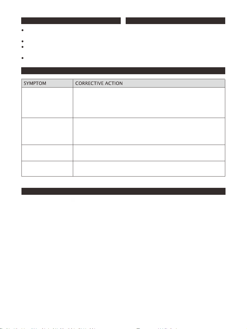
Ensure the breaker supplying the dryer is operational. If it is,
disconnect the power and remove the hand dryer cover. Check all
the wire connection to sure they are well fixed.
Turn on power and if it does not work then replace circuit board.
Turn motor blower several times by hand to see it is blocked.
Ensure that there is no obstruction on or in front of the infrared
sensor zone. Clean any dirty off the sensor lens.
Try adjusting the sensitivity potentiometer on program board. If
not still not work, replace circuit board and sensor board.
Check if the heat element switch is power on.
Check if the heat element was broken. If yes, replace a new one.
Check the motor brush worn condition. Replace them or a new
motor.
The hand dryer is also workable with Coarse Particulate Filter. The dryer has a coarse particulate
air filter to prevent lint and debris build up that can damage the motor and heating element.
Routine replacement or cleaning of the air filter is needed to maintain
the dryer in good operating condition. With light to moderate wash room traffic, replacing or
cleaning the air filter once a year is recommended. If the wash room traffic is high, the air filter
should be replaced or cleaned every 6 months.
Page 4
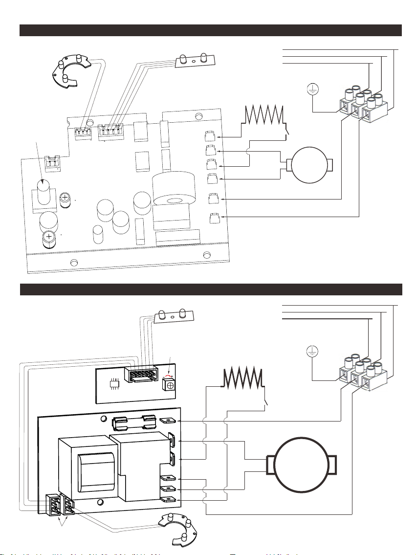
11. DIAGRAM FIXED SPEED ADJUSTABLE CIRCUIT BOARD
LED L ight Ass embly
Sen s
emb ly
Ass
or
220 V-240V 5 0/ 60Hz
Speed
Adjustable
Knob
Main C
uit Board
irc
Heat i
Moto r
Heat ing
Moto r
Powe r
Powe r
Bla ck
ng
12. DIAGRAM FIXED CIRCUIT BOARD WITHOUT SPEED ADJUSTABLE
emb ly
Ass
Sen sor
220 V-240V 5 0/60H z
Hea t Eleme nt
Bla ck
Blu e
Bro wn
L
N
G
L
N
G
Gro undin g
HOT /COLD
SWI TCH
Motor
Yello w
Termi nal Blo ck
Mai n Board As sembl y
The se two co nnect or
is in terch angea ble
Pro gram
B
oar d
Ass embly
Turn c lockw ise to
rea se sens or rang e
inc
er
Pow
Mot or
Hea ting
Pow er
Mot or
Hea ting
Hea t Eleme nt
Bla ck
Bla ck
LED L ight Ass embly
Blu e
Bro wn
HOT /COLD
SWI TCH
Motor
Gro undin g
Yello w
Termi nal Blo ck
 Loading...