

Page 1
Pebble
Plug & Play
User Manual
Page 2
TECHNICAL SPECIFICATIONS
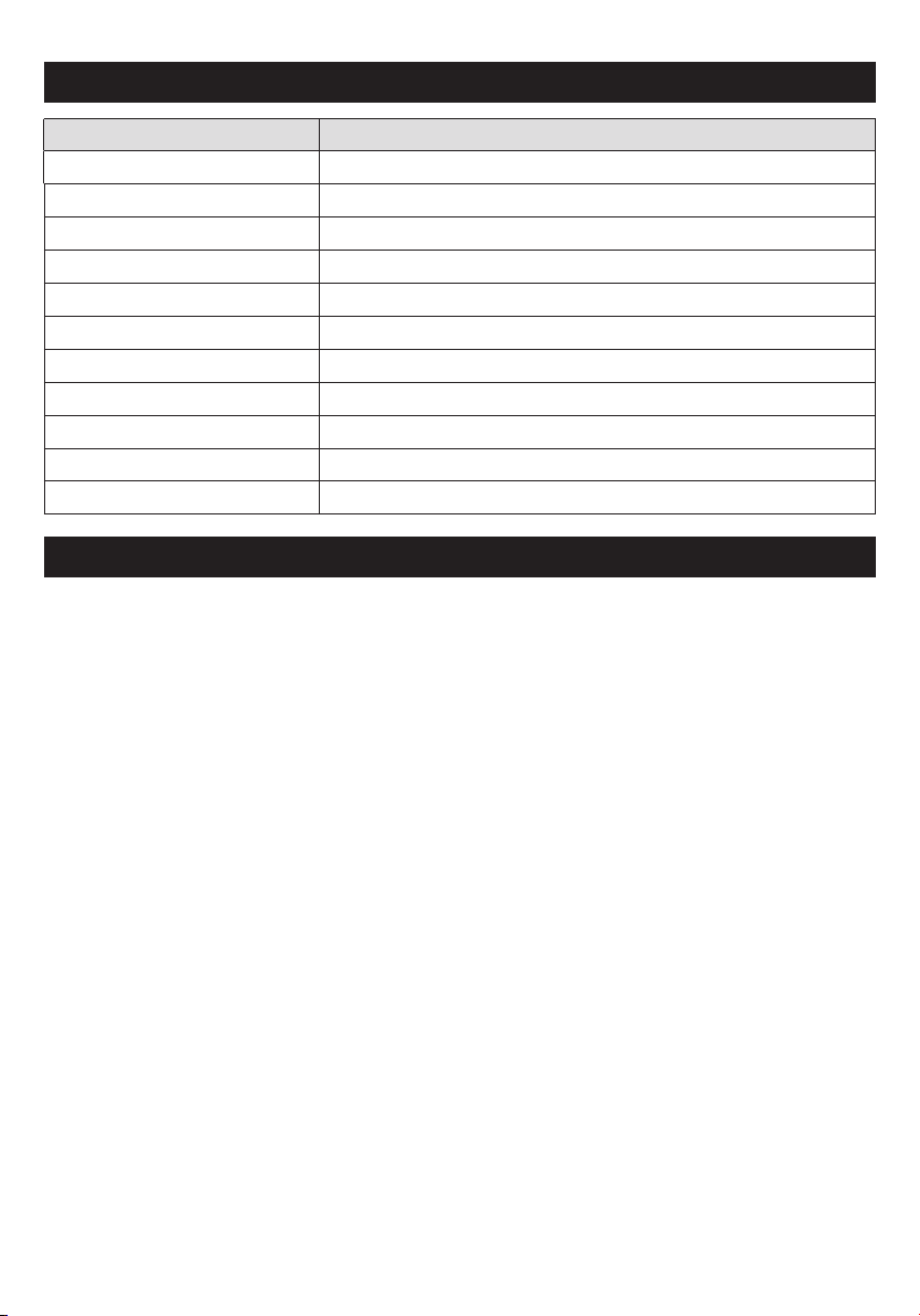
Item Category Performance Date
Operating Voltage
Standby Power
Warm Air Speed Output
Motor Type
Sensor Type
Sensor Range
Timing Protection
Drying Time
Drip Proof
Isolation
Unit Size
AC 220~240V, 50/60 Hz, 300W (No Heat) / 700W (Heat)
≤0.5 W
96 m/s
Brushless DC Motor, 30,000 RPM
Auto Infrared touch free operation
45° 10~20cm
50 seconds auto shut off
10 ~ 12 sec
IPX3
CLASS I
H 322.1mm x W 270.5mm x D 144.6mm
IMPORTANT SAFETY INSTRUCTIONS
WARNING – TO REDUCE THE RISK OF FIRE, ELECTRIC SHOCK, OR
⚠
•
•
•
•
•
•
•
•
•
INJURY TO PERSONS OBSERVE THE FOLLOWING:
Use this unit only in the manner intended by the manufacturer. Manufacturer is not
responsible for damages caused by misuses or defective installations.
The instructions contained within the installation Template enclosed must be followed
carefully when installing this unit. Failure to accurately follow the instructions may
result in the incorrect operation of this unit, damage to property and/or personal injury.
Installation work and electrical wiring must be done by qualified person(s) in
accordance with all applicable codes and standards, including fire-rated construction.
When cutting or drilling into wall or ceiling, do not damage electrical wiring and other
hidden utilities.
This unit must be powered by a dedicated circuit branch protected by a circuit
breaker with the appropriate rating. Circuit cable must be fit current consumption for
this unit.
This unit has been designed for indoor use only, protect from water, sun and extreme
temperatures, do not install it outdoors or close to moisture and heat generators.
This unit can only be revised, maintained, repaired and removed by qualified person(s).
If the unit stops and works strangely, contact your regional dealer or contractor.
This appliance can be used by children aged from 8 years and above and persons
with reduced physical, sensory or mental capabilities or lack of experience and
knowledge if they have been given supervision or instruction concerning use of the
appliance in a safe way and understand the hazards involved. Do not allow children to
play with the appliance or carry out cleaning and user maintenance on this hand dryer.
If the supply cord is damaged, it must be replaced by the manufacturer, its service
agent or similarly qualified persons in order to avoid a hazard.
3
Page 3
UNPACKING
1. Remove all packing material. Recycling is recommended.
2. Carefully remove the hand dryer from the shipping carton, using care not to drop the appliance.
3.
Inspect carefully for any damage that may have occurred during transit. Check for any loose, missing
or damaged parts. If the hand dryer is damaged, promptly inform the shipper or dealer where you
purchased it.
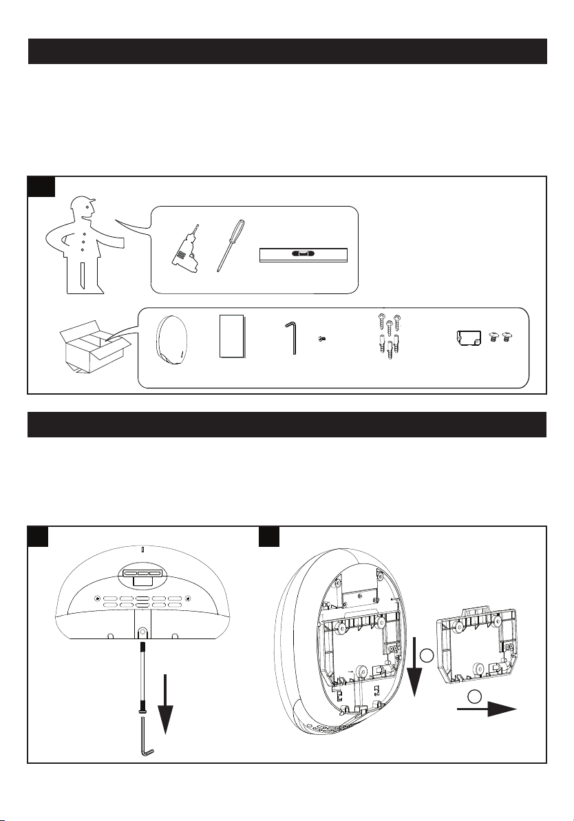
Standard items with the hand dryer are shown in Fig.1 together with tools need by the installer.
1
Unit
Installation
template
Service Tool
& Spare Screw
Wall mounting
anchors with screws
Power cable cover
& Screw
INSTALLATION
1. Wall bracket removal
1.1 Place the appliance on a cloth to avoid marking its surface.
1.2 Remove the one security screw seated on the bottom surface of the unit, using the service
tool (fig.2). 1.3 Pull down the wall mounting bracket and remove from the unit (fig.3).
2 3
1
2
4
Page 4
CAUTION
• Make sure power supply breaker is switched off.
Check that the electrical supply corresponds to that shown on the rating plate. If the unit is
•
connected to any electrical supply other than stated on the rating plate of the unit, permanent
damage or unsafe operation of the unit may result.
The unit must be mounted on a flat vertical wall capable of supporting the full weight of the unit.
•
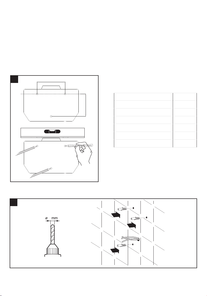
2. Positioning
2.1 Mark the location on the wall with a pe
three fixing points (fig. 4).
4
•
100mm
ncil. Use the Installation Template to mark the locations for the
Recommended height measurements form the
floor to top screws
Installation target
Adult male
80mm
2.2 Pre-drill the wall in the marked locations using 5/16” (8mm) drill, insert the plastic anchors and
tap flush to the wall. If the cable entry is to be done from the wall provide a proper cable exit (fig. 5)
Adult female
Children 5-8 years old
Children 8-11 years old
Children 11-14 years old
Wheelchair user
Height
1400mm
1365mm
1028mm
1128mm
1208mm
1150mm
5
8
5
Page 5
EN
3. Installing Power cable & Connection terminal block
WARNING: ENSURE POWER NOT CONNECTED
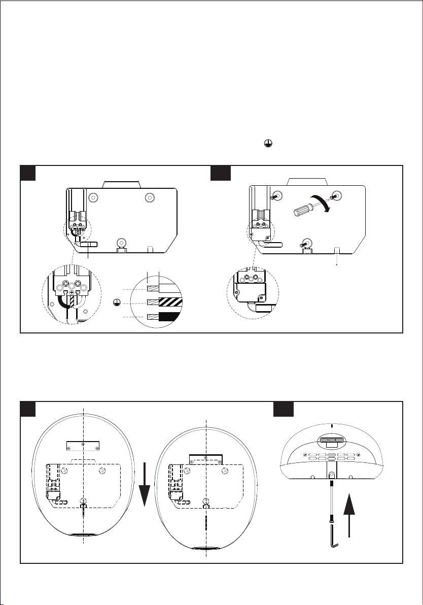
3.1 Pull the cable through the hole in the wall mounting bracket. Ensure the cable is long enough to route
correctly through the wall mounting bracket to the terminal block (fig. 6).
3.2 The cable must sit in the dedicated channel.
3.3 As shown, connect cable to terminal block.
3.4 Screw in terminal block.
3.5 Fix the wall mounting bracket to the wall. Screw to the wall using the appropriate fitting (fig 6A).
3.6 Fix the cable cover with screw on the wall mounting bracket.
CAUTION: Connect the ground wire to the terminal block marked “ ”
Do not over-tighten and crush the power cable.
6
Power Cable Entry
L N
6mm
N
6A
Power Cable Exit
(in case with power cord cable)
L
4. Fix the Main unit to Wall mounting bracket
4.1 Position the unit centrally above the wall mounting bracket so the metal bracket on the rear is positioned
over the mating part of the wall bracket moulding. Keeping the dryer firmly against the wall, slowly slide the
dryer down until there is no further travel. The dryer should then be electrically connected (fig 7).
4.2 Insert and tighten the security screw seated on the bottom surface (fig 7A).
7 7A
5. Turn power on and test the unit for correct operation.
6
Page 6
EN
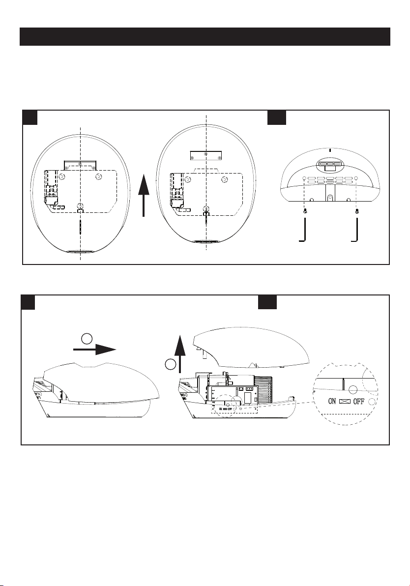
Heater Swicth ON/OFF & Filter replacing
1. Heater Switch ON/OFF (factory default setting “ON”)
1.1 Remove the one security screw seated on the bottom surface from the unit, using the
1.2 Lift the unit off the wall mounting bracket (fig. 8).
Note: Ensure the LED light on the front of the unit is OFF before opening the front cover, if the LED light
is still ON, wait until the light goes off.
service tool
(fig. 2).
8
1.3 Remove the (2) security screws from the unit, using the service tool (fig 8A).
1.4 Lift the front cover off the unit (fig. 9).
9
1
2
8A
9A
1.5 To turn off or turn on, use the switch shown in fig. 9A.
ATTACHING UNIT
Reposition the front cover on the unit.
Insert and tighten two security screws into the bottom of the front cover (fig. 8A).
Reposition the unit on the wall mounting bracket and insert and tighten one
of front cover (fig. 7~7A).
Test the unit for correct operation. The LED light on the cover should light continuously after the power
supply has been correctly connected.
Note: If the LED light remains off, the unit must be fitted correctly.
security
screw into the bottom
7
Page 7
EN
2. Filter replacing (If clean air filter option is applicable for your unit)
If the LED light on the front of the unit flashes red then the filter needs to be changed. The filter functions
approximately 60,000 uses
2.1 Remove the one security screw from the middle
2.2 Lift the unit off the TERRA4 wall mounting bracket (fig. 8).
2.3 Remove the (2) security screws from the unit, using the service tool (fig. 8A).
2.4 Lift the front cover off the unit (fig. 9).
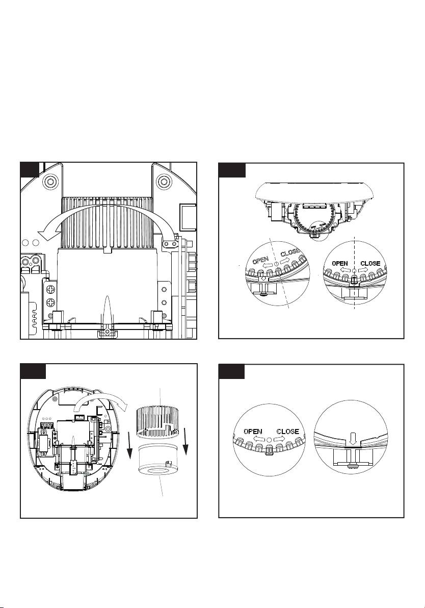
2.5 Turn the filter cover to open direction (fig. 10).
The dot is aligned with the arrow present on the motor cover (fig. 10A).
Note: Ensure the LED light on the front of the Unit is OFF before opening the front cover, if the LED
light is still ON, wait until the light goes off.
of the bottom face of the unit (fig.2).
10 10A
CLOSE
OPEN
(A) (B)
2.6 Remove the filter(fig. 10B).
10B 10C
Filter Cover
Filter
2.7 Insert the New filter.
The dot on the filter cover is aligned with the arrow on the motor cover (fig.10C).
2.8 Turn the filter cover to close direction. The dot i
cover (fig.10A-A).
8
1
s positioned to the right of the arrow on the motor
Page 8
EN
ATTACHING UNIT
Reposition the front cover on the Unit.
Insert and tighten two security screws into the bottom of the front cover (fig. 8A).
Reposition the unit on the wall mounting bracket and
of front cover (fig. 7~7A).
Test the unit for correct operation. The LED light on the cover should flash 3 times with a red light after
the power supply has been correctly connected and fol
Note: On power up the red LED light should not flash this means the new filter is fitted correctly.
Warning - The filter must be replaced with a new f
!
will stop after 75,000 operations. The red LED
front of the cover until the filter is replaced.
insert and tighten one
lowed by continuous light white LED.
ilter after 60,000 operations and if not the unit
will be flashing on the window positioned at the
security
screw into the bottom
Operating LED Light
LED Lighting for standard and Black Edition
Front cover color Stand by Mode Working Mode Filter Alert
White / Silver White LED ON White LED Moving
Black Edition Red LED ON Red LED Moving
Filter Alert Lighting
Filter uses
From 60,000 uses
~74,999 uses
From 75,000 uses
~ till reset
Motor STOP
Lights Stand by Mode
White LED White LED ON White LED Moving
Red LED Red LED Blinking OFF
Pointing LED (blue)
White LED White LED ON
Red LED Red LED Blinking
Pointing LED (blue) OFF
OFF ON
See below' Filter
alert lighting' Table
Working Mode
(sensing mode)
White LED ON
Red LED Blinking
Blinking
Use
1. No touch operation.
2. Shake excess water from hands.
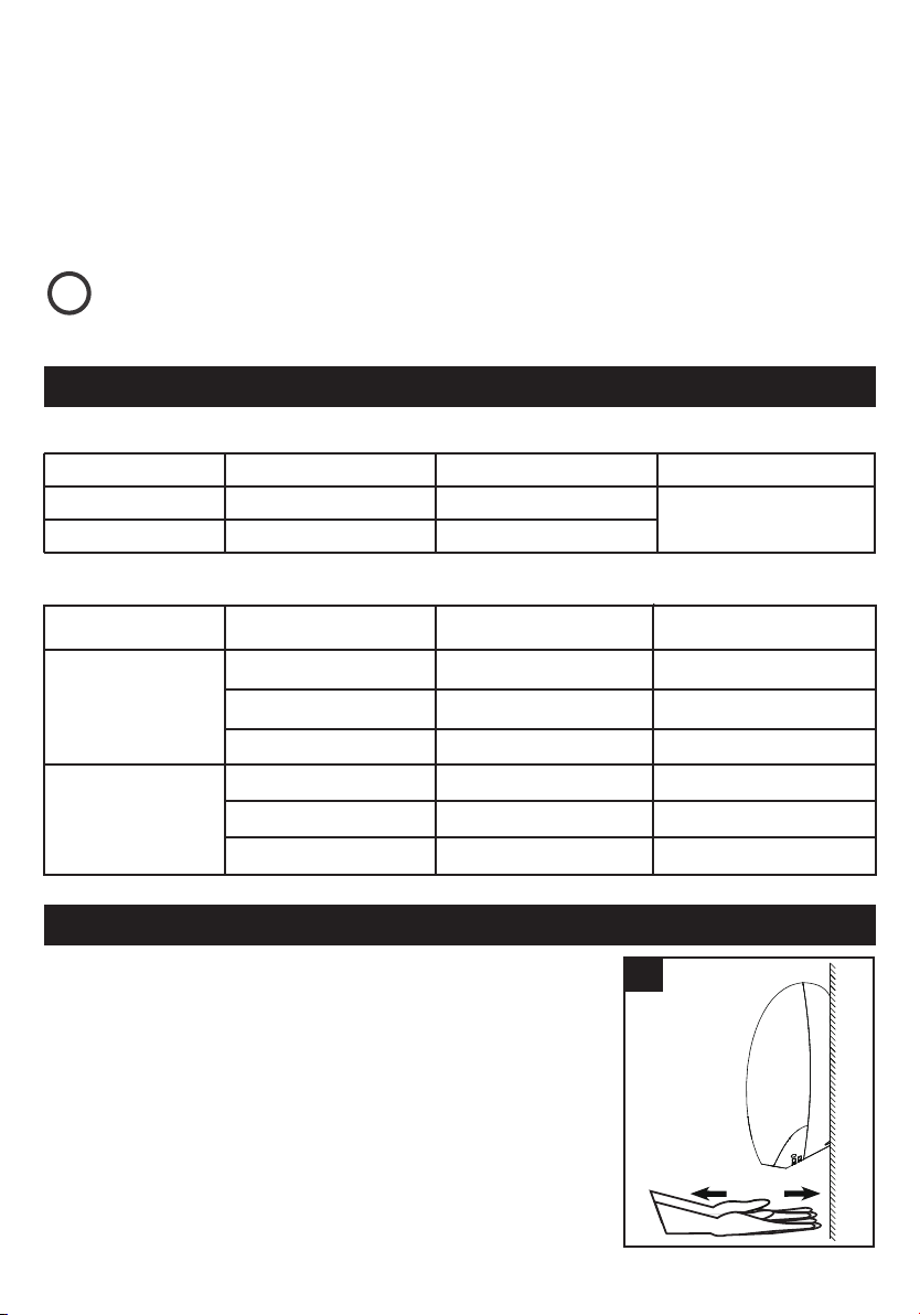
3. Place hands under the outlet to start operation (fig. 11).
Slowly move hands back and forth through the hand dryer.
4.
5. The blue LED are placed under the dryer outlet at the bottom starts
with drying operation.
6. The dryer stops when hands are removed.
7. Hand dryer also auto shuts off after 50 seconds of uninterrupted use.
If there is an electrical or motor problem, the blue LED will flash when
hands off the placed under the dryer outlet.
11
9
Page 9
EN
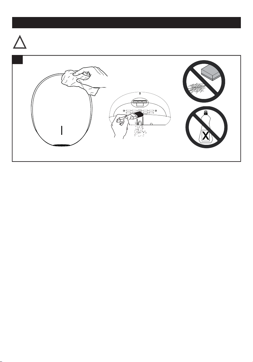
Maintenance and cleaning
Lift the Unit off the wall mounting bracket before maintenance or repair
!
.
12
Regular maintenace
Regularly clean the outer casing use a soft, damp cloth to gently wipe away any dirt.
CAUTION: Never use abrasives or chemicals to clean the cover. Do not soak.
Periodical deep clean
1. Clean and maintenance must not taken until the unit has been removed from the wall mounting bracket or cut off
power.
2. Use the service tool or security hex driver to remove the two cover security screw.
3. Remove the cover.
4. Clean all dust and lint from the interior of the hand dryer.
5. Replace the cover.
6. Wipe the cover with a damp cloth.
10
 Loading...