

Page 1

b
b
CloudCell 4Gb
b
Installation manualb
b
b
b
b
Page 2

Written byɉ
Paula Araujo IT Project and Process Managerb
Alexey Shorokhovb Industrial Designerb
Reviewed byɉ
Tim Kipleyb Infrastructure directorb
Vitaly Klebanb CTOb
Slava Vitykb Hardware engineerb
b
b
bb
everynet.com 2ɉ
Page 3

ɉ
Content ɉ
Objectives part 1 4ɉ
Terms of use part 2 4ɉ
Warranty part 3 5b
Components part 4 7b
4.1 CloudCell Gateway 7b
4.2 Outdoor Omnidirectional Antenna 7b
4.3 RF jumper cable 8b
4.4 Lightning protector 8b
4.5 Two Micro SIM cards 8b
4.6 Grounding straps 9b
4.7 Butyl mastic tape 9b
4.8 Clamps and cable ties 9b
4.9 Ethernet cabling 10b
4.10 Recommended equipment 11b
Preparing the Gateway and cabling the network part 5 13b
5.1 Connectors specification 13b
5.2 Grounding 14b
5.3 Mount Antenna 14b
5.4 Mount Gateway 16b
5.5 Connect RF jumper cable to the gateway 19b
5.6 Ethernet to gateway cable connection 20b
5.7 Ethernet to PoE adapter cable connection 23b
5.8 Verify all the connectors are correct 26b
5.9 Check LEDs indication 26b
5.10 Verify gateway is affixed securely on the tower 27b
History of revision part 6 28b
Red 28b
FCC 30b
b
b
ɉɉ
everynet.com 3ɉ
Page 4

Objectives part 1ɉ
The purpose of this document is to provide cabling, installation, and bootup instructions of abbbb bbbbb bbb bbb
Everynet gateway in an external or tower environment.b
Terms of use part 2ɉ
● Installer MUST strictly follow installation requirements as conditions of product warranty.b
● Gateways MUST be professionally installed and it is the professional installer’s responsibilityb
to make sure the gateway is properly configured and operated within local country regulatoryb
requirements.b
● There are no operator serviceable parts inside this equipment. Service MUST be provided onlyb
by a qualified service technician approved by gateway manufacturer.b
● Compliance is required with respect to voltage, frequency, and current requirements indicatedb
by manufacturer. Connection to a different power source than those specified may result inb
improper operation, damage to the equipment or pose a fire hazard.b
● PoE power source must have a detachable power cord which has an integral safety ground wireb
connection to a grounded safety outlet.b
● Do not substitute the power cord with one that is not the provided approved type. Never useb
an adapter to connect a 3-wire cable to a 2-wire outlet as this will damage the equipment.b
● The equipment requires the use of the ground wire as a part of the safety certification.b
Modification or misuse may provide a shock hazard that could result in serious injury or death.b
● Contact a qualified electrician or the manufacturer if there are questions about the installationb
prior to connecting the equipment.b
● Protective earthing is provided by approved PoE adapter. Building installation shall provideb
appropriate short-circuit and GFI protection.b
● Protective bonding must be installed in accordance with local national wiring rules andb
regulations.b
● Surge protection and grounding should be used for all outdoor installationsb
● Equipment cabinet located on the bottom of the tower should be grounded to the groundingb
system of the tower.b
● Shielded Category 5 (or above) cabling with drain wire and earth grounding MUST be used forb
all terminations of wired connections.b
● Ethernet cable MUST be properly grounded through the AC ground of the PoE.bb
● Gateway should be grounded to the grounding point on the tower. It is not permitted to groundb
a gateway directly to the tower structures.b
● Lightning arrestor MUST be used to protect for the gateway, lighting protection should beb
grounded to the grounding point on the tower. It is not allowed to ground a lighting protectorb
directly to the tower structures.b
● All coaxial connections should be properly weatherproofed.b
● Gateway should be attached to tower pole using metal ties. Use of plastic / nylon ties isb
prohibited.b
everynet.com 4ɉ
Page 5

Warrantyɉ part 3ɉ
Limited Warrantyɉ
Everynet, B.V. (“EVERYNET”) warrants that the product(s) furnished hereunder (the “Product(s)”)b
shall be free from defects in material and workmanship for a period of one (1) year from the date ofb
shipment by EVERYNET under normal use and operation. EVERYNET sole and exclusive obligationb
and liability under the foregoing warranty shall be for EVERYNET, at its discretion, to repair orb
replace any Product that fails to conform to the above warranty during the above warranty period.b
The expense of removal and reinstallation of any Product is not included in this warranty. Theb
warranty period of any repaired or replaced Product shall not extend beyond its original term.b
Warranty Conditionsɉ
The above warranty does not apply if the Product:b
● Has been modified and/or altered, or an addition made thereto, except by EVERYNET, orb
EVERYNET’ authorized representatives, or as approved by EVERYNET in writing;b
● Has been painted, rebranded or physically modified in any way;b
● Has been damaged due to errors or defects in cabling;b
● Has been subjected to misuse, abuse, negligence, abnormal physical, electromagnetic or electricalb
stress, including lightning strikes, or accident;b
● Has been damaged as a result of using third party firmware;b
● Has no original EVERYNET label, or is missing any other original EVERYNET label(s); orb
● Has not been received by EVERYNET within 30 days of issuance of the RMA.b
● In addition, the above warranty shall apply only if: the product has been properly installed andb
usedbb
● At all times in accordance, and in all material respects, with the applicable Productb
documentation; all outdoor installation cabling runs use braided, shielded and grounded Ethernetb
CAT5 (or above), and for indoor installations, indoor cabling requirements are followed.b
Returnsɉ
No Products will be accepted for replacement or repair without obtaining a Return Materialsb
Authorization (RMA) number from EVERYNET during the warranty period, and the Products beingb
received at EVERYNET facility freight prepaid in accordance with the RMA process of EVERYNET.b
Products returned without an RMA number will not be processed and will be returned freight collectb
or subject to disposal.bb
Disclaimerɉ
EXCEPT FOR ANY EXPRESS WARRANTIES PROVIDED HEREIN, EVERYNET, ITS AFFILIATES ANDb
ITS AND THEIR THIRD PARTY DATA, SERVICE, SOFTWARE AND HARDWARE PROVIDERSb
HEREBY DISCLAIM AND MAKE NO OTHER REPRESENTATION OR WARRANTY OF ANY KIND,b
everynet.com 5ɉ
Page 6

EXPRESS, IMPLIED OR STATUTORY, INCLUDING, BUT NOT LIMITED TO, REPRESENTATIONS,b
GUARANTEES, OR WARRANTIES OF MERCHANTABILITY, ACCURACY, QUALITY OF SERVICEb
OR RESULTS, AVAILABILITY, SATISFACTORY QUALITY, LACK OF VIRUSES, QUIET ENJOYMENT,b
FITNESS FOR A PARTICULAR PURPOSE AND NON INFRINGEMENT AND ANY WARRANTIESb
ARISING FROM ANY COURSE OF DEALING, USAGE OR TRADE PRACTICE IN CONNECTIONb
WITH SUCH PRODUCTS AND SERVICES. BUYER ACKNOWLEDGES THAT NEITHER EVERYNETb
NOR ITS THIRD PARTY PROVIDERS CONTROL BUYER’S EQUIPMENT OR THE TRANSFER OFb
DATA OVER COMMUNICATIONS FACILITIES, INCLUDING THE INTERNET, AND THAT THEb
PRODUCTS AND SERVICES MAY BE SUBJECT TO LIMITATIONS, INTERRUPTIONS, DELAYS,b
CANCELLATIONS AND OTHER PROBLEMS INHERENT IN THE USE OF COMMUNICATIONSb
FACILITIES. EVERYNET, ITS AFFILIATES AND ITS AND THEIR THIRD PARTY PROVIDERS AREb
NOT RESPONSIBLE FOR ANY INTERRUPTIONS, DELAYS, CANCELLATIONS, DELIVERYb
FAILURES, DATA LOSS, CONTENT CORRUPTION, PACKET LOSS, OR OTHER DAMAGEb
RESULTING FROM ANY OF THE FOREGOING. In addition, EVERYNET does not warrant that theb
operation of the Products will be error free or that operation will be uninterrupted. In no event shallb
EVERYNET be responsible for damages or claims of any nature or description relating to systemb
performance, including coverage, buyer’s selection of products (including the Products) for buyer’sb
application and/or failure of products (including the Products) to meet government or regulatoryb
requirements.b
Limitation of Liabilityɉ
EXCEPT TO THE EXTENT PROHIBITED BY LOCAL LAW, IN NO EVENT WILL EVERYNET OR ITSb
SUBSIDIARIES, AFFILIATES OR SUPPLIERS BE LIABLE FOR DIRECT, SPECIAL, INCIDENTAL,b
CONSEQUENTIAL OR OTHER DAMAGES (INCLUDING LOST PROFIT, LOST DATA, ORb
DOWNTIME COSTS), ARISING OUT OF THE USE, INABILITY TO USE, OR THE RESULTS OF USEb
OF THE PRODUCT, WHETHER BASED IN WARRANTY, CONTRACT, TORT OR OTHER LEGALb
THEORY, AND WHETHER OR NOT ADVISED OF THE POSSIBILITY OF SUCH DAMAGES.b
ɉ
ɉ
ɉɉ
everynet.com 6ɉ
Page 7
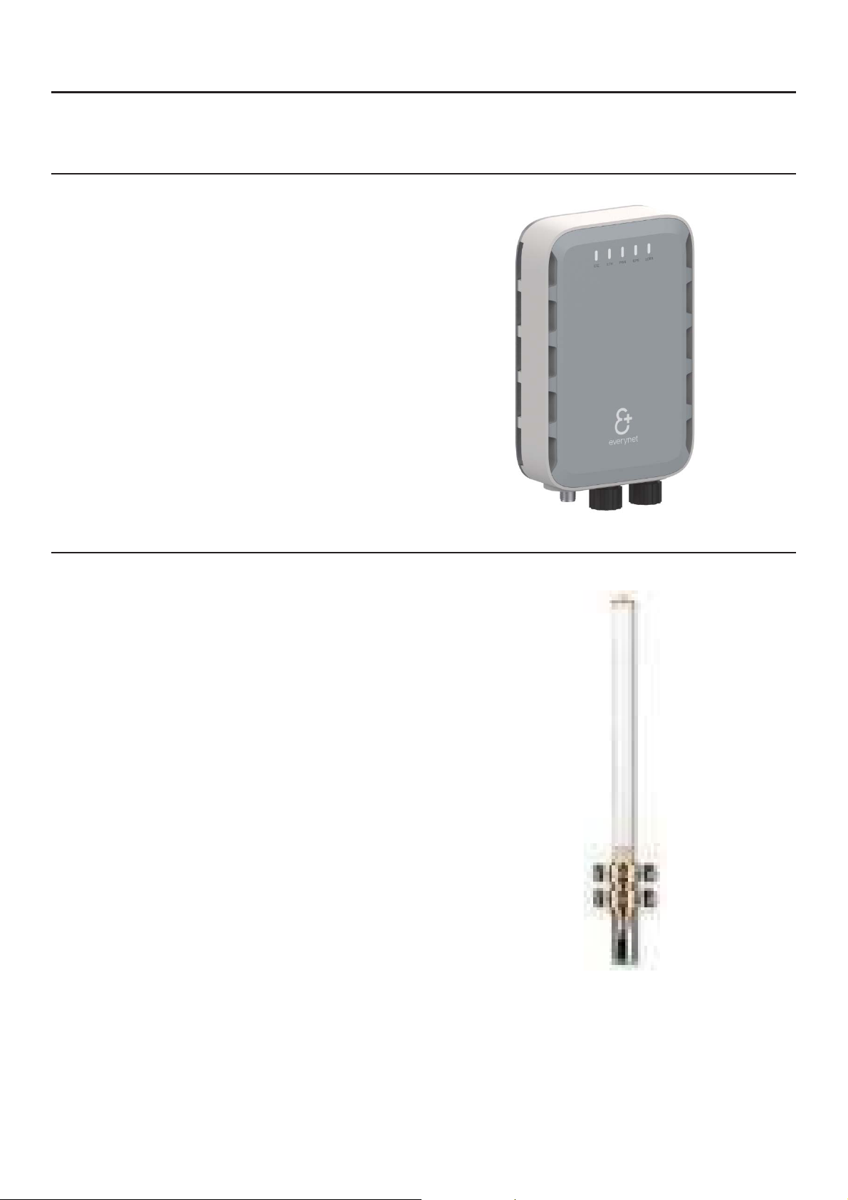
Componentsɉ part 4ɉ
b
4.1 CloudCell Gatewayɉ
● 48VDC PoE inputb
●
●
●
●
●
●
●
b
●
●
●
b
b
LoRa antenna must meet these minimumb
●
●
b
●
●
●
●
●
●
b
15W power consumptionb
Triple redundant backhaulb
Weatherproof ethernet jackb
Externally accessible dual SIM slotb
Internal antenna optionb
4 hour internal batteryb
Tropical/Equatorial environment operation
High visibility status LEDsb
Pre-loaded Everynet Agentb
Pre-configured VPN for Everynet RANb
4.2 Outdoor Omnidirectional Antennaɉ
specificationsb
b
50 Ohm N female connectorb
868 MHz or 915 MHz frequency range.b
Please select frequency range depending on
local RF regulations and gateway model.b
UV protected and IP67 ratedbb
125 mph wind loadb
Metal mounting bracket for pole mountb
-40 c to + 85 c temp rangeb
Antenna must be installed perpendicular tob
the ground +/-1 degreeb
Antenna must have lightning arrestorb
installed at N connector and groundedb
directly to tower grounding pointb
everynet.com 7ɉ
Page 8
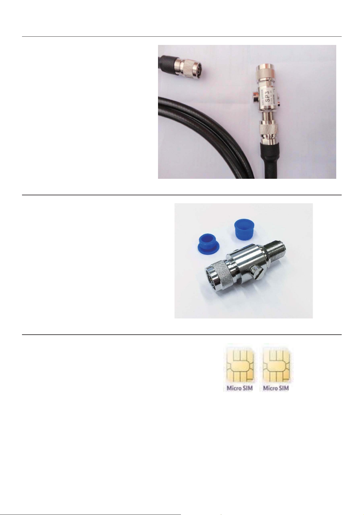
4.3 RF jumper cableɉ
Please make sure that RF jumper cableb
●
●
b
●
●
●
b
b
Please make sure that lightning protectorb
●
●
●
●
●
●
●
b
Please make sure the SIM cards meet theb
●
●
●
●
●
b
b
meets these minimum specificationb
b
50 Ohm N male connectorb
50 Ohm LMR240 or LMR400 type
cableb
UV protected and weatherproofb
1 meter lengthb
-40 to +85*C temperature rangeb
4.4 Lightning protectorɉ
meets these minimum specificationb
N male on antenna sideb
N female on equipment sideb
0.4dB max insertion lossb
DC-2GHz operation rangeb
90V breakdown voltageb
30W max input powerb
-40 to +85*C temperature rangeb
4.5 Two Micro SIM cardsɉ
following specificationb
b
M2M 1GB data per month per SIM cardb
Do not use cellular phone data SIMb
Access to the SIM management platformb
for troubleshooting purposesb
-40 to +85 c temp rangeb
Each SIM selected must be from differentb
carrier using different infrastructure andb
backhaulb
b
b
everynet.com 8ɉ
Page 9
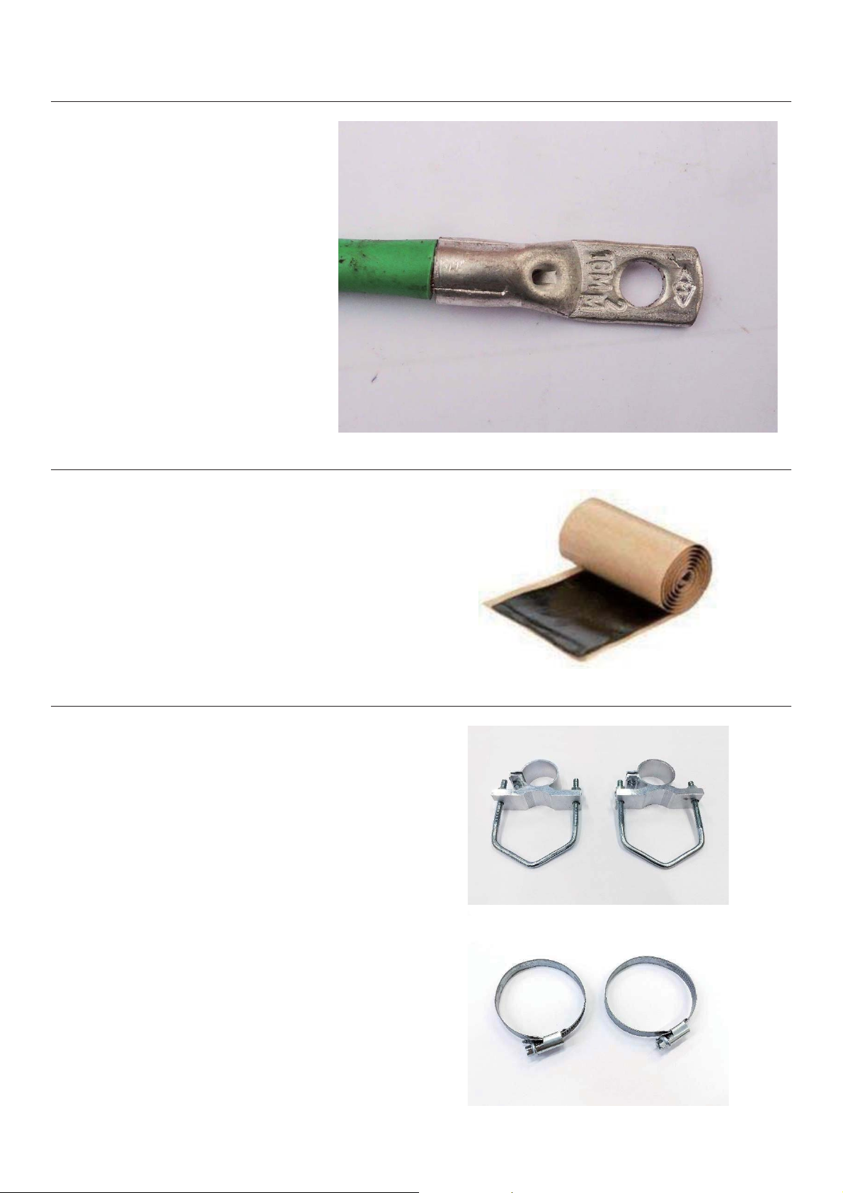
4.6 Grounding strapsɉɉ
● Cable minimum diameter 2.5b
●
●
●
●
b
b
●
b
b
● 3M Butyl Mastic Tape 2212 - 3M IDb
b
Antenna mounting clampsb
●
b
●
●
b
Clampsb
●
●
b
b
mm2 or 14 AWGb
Must use termination lugsb
Grounding bolt on CloudCell isb
5mm diameterb
Grounding bolt on lightningb
protector is 3mmb
Ground directly to towerb
grounding points only using anti
oxidation agent and appropriate
lugsb
Two grounding straps requiredb
4.7 Butyl mastic tapeɉɉ
7000133439b
b
4.8 Clamps and cable tiesɉ
Use only manufacturer approved mounting
brackets to attach antennab
Follow antenna manufacturerb
recommended proceduresb
Do not use any other attachment methodb
Use only high quality stainless steel ringb
clamps to securely attach gateway tob
mounting poleb
Do not use plastic zip ties for attaching theb
gatewayb
everynet.com 9ɉ
Page 10
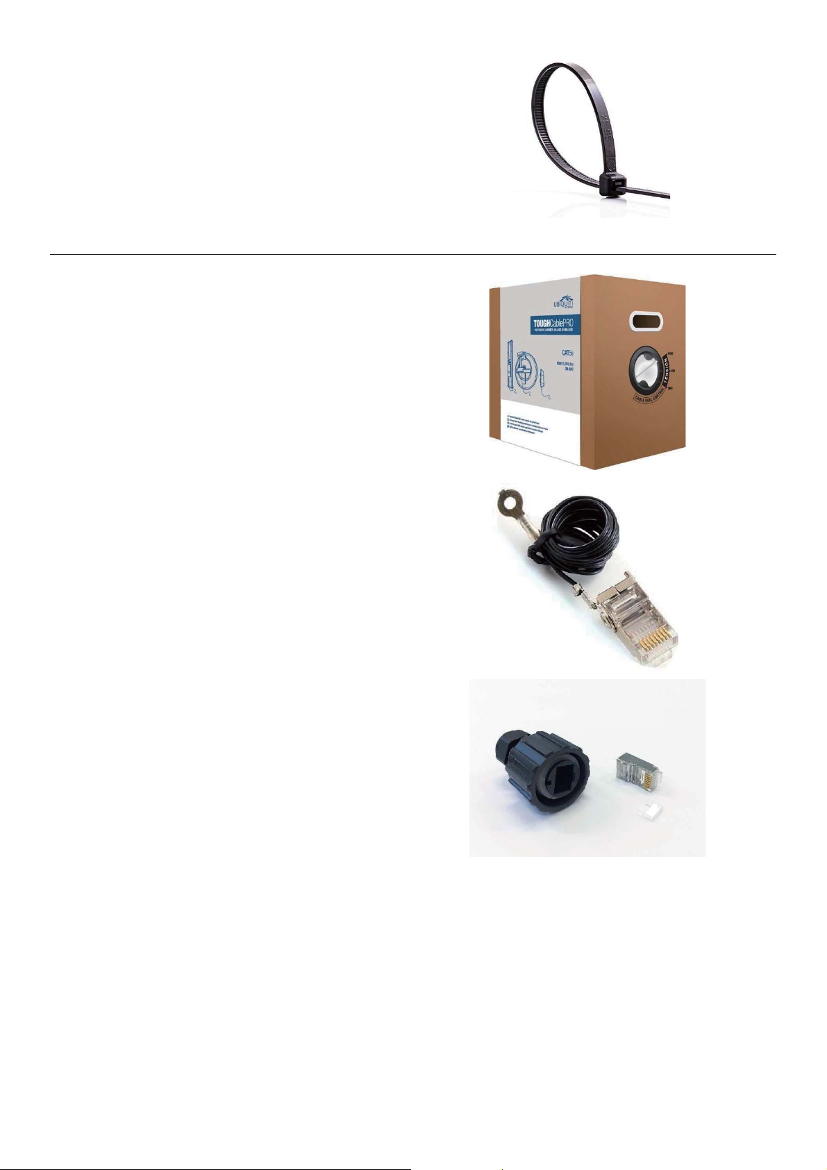
Cable tiesb
●
20 cm and 35 cm lengthsb
●
● Weather resistant and continuous exposureb
●
b
Ubiquiti TOUGHcable PRO Carrierb
●
●
●
●
●
●
b
Grounded ethernet connector (PoE side)b
● Ubiquiti TC-GNDb
b
Ethernet connector and boot (gateway side)b
●
● Ubiquiti TC-CONb
b
UV stabilized Nylon 6/6b
outdoor use ratedb
50-pound testb
4.9 Ethernet cablingɉ
Outdoor use CAT5eb
UV protectedb
24 AWGb
Braided shieldb
Foil Shieldb
Ground wireb
b
b
CONEC 17-10001bb
everynet.com 10ɉ
Page 11
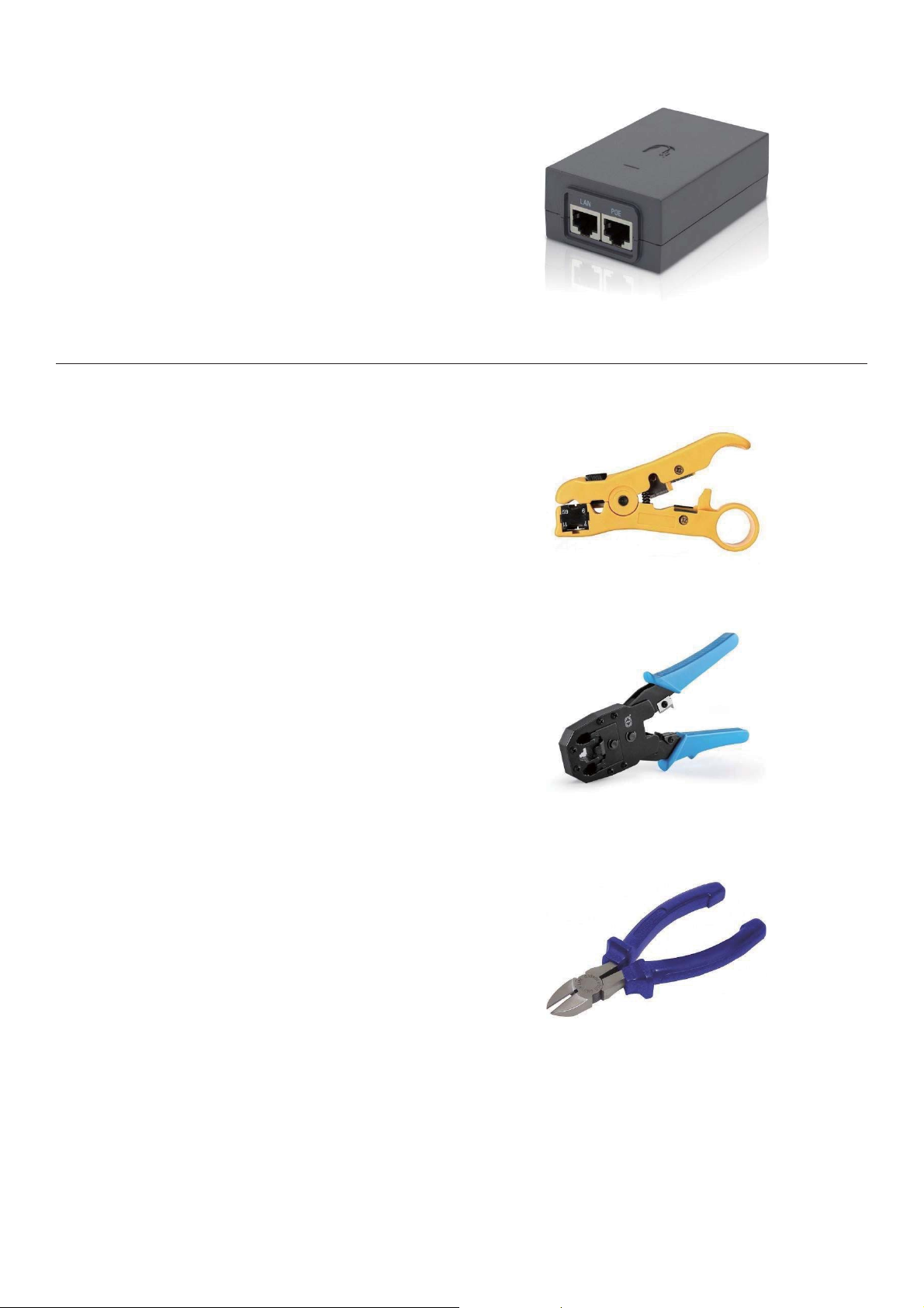
PoE adapterb
b
● Ubiquiti 48 volt 24 watt PoE injector MPN:b
● Use only 3 pin grounded power cord for PoEb
b
b
b
● Wire stripper/cutterb
b
● 8P8C cable crimping pliersb
b
● Cutting pliersb
b
POE-48-24Wb
powerb
b
NOTE: Verify with continuity meter that earth
grounding pin of PoE power cable isb
continuous thru the power cord.b
4.10 Recommended equipmentɉ
everynet.com 11ɉ
Page 12
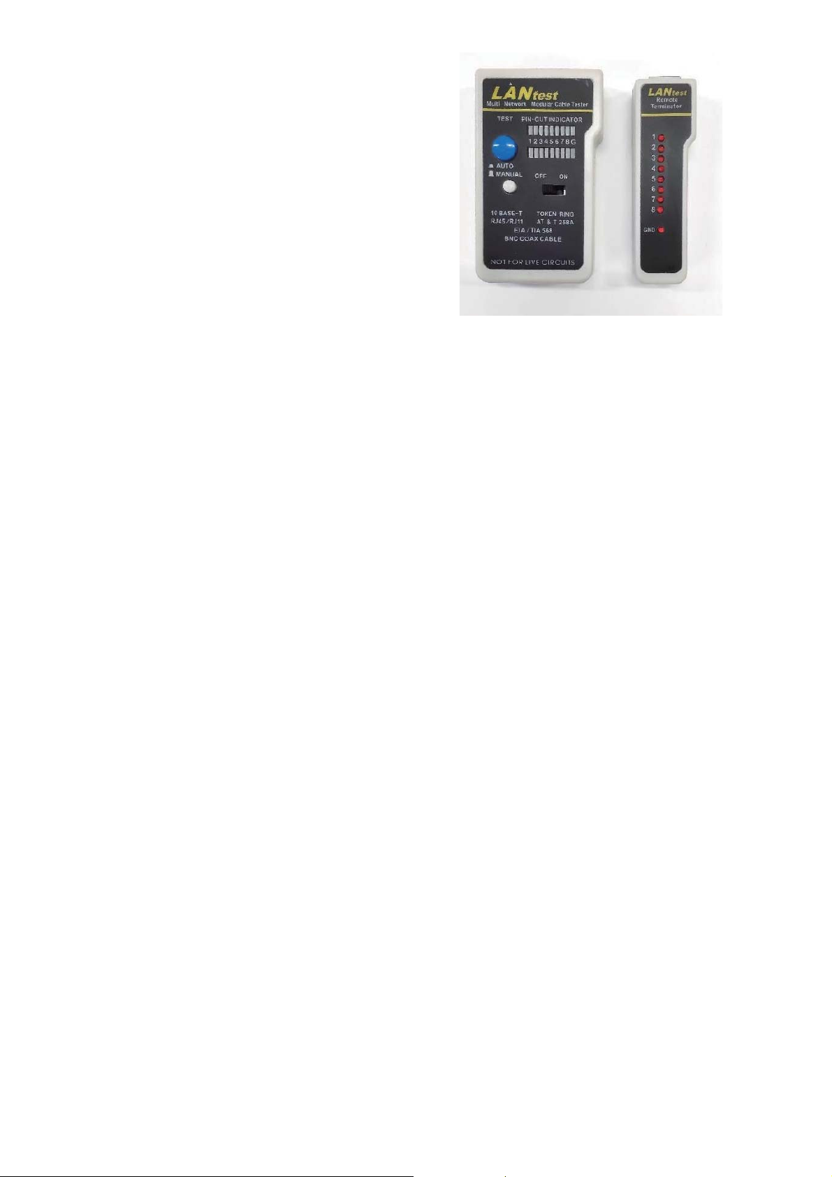
● Cat5 cable testerb
b
bb
everynet.com 12ɉ
Page 13
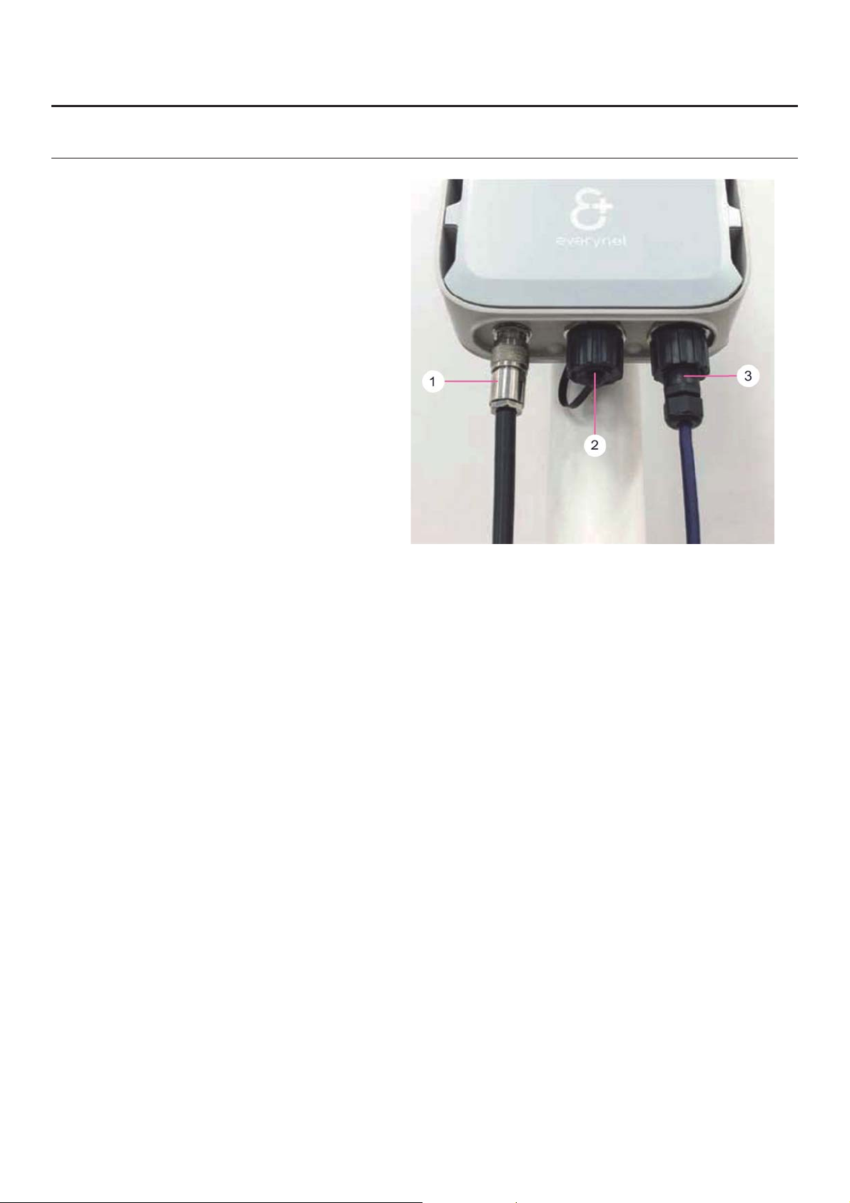
Preparing the Gateway and cabling the network part 5ɉ
5.1 Connectors specificationɉ
1. LoRa radio cableb
2.
3.
b
SIM cards holders + USB + resetb
Ethernet cableb
everynet.com 13ɉ
Page 14
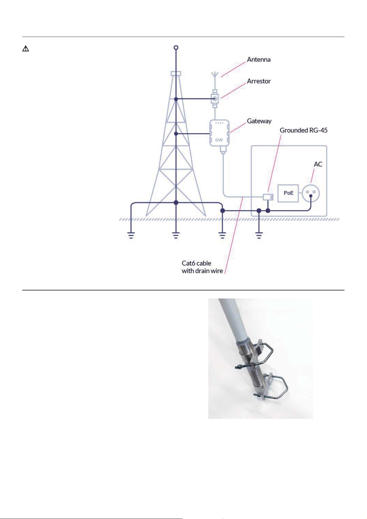
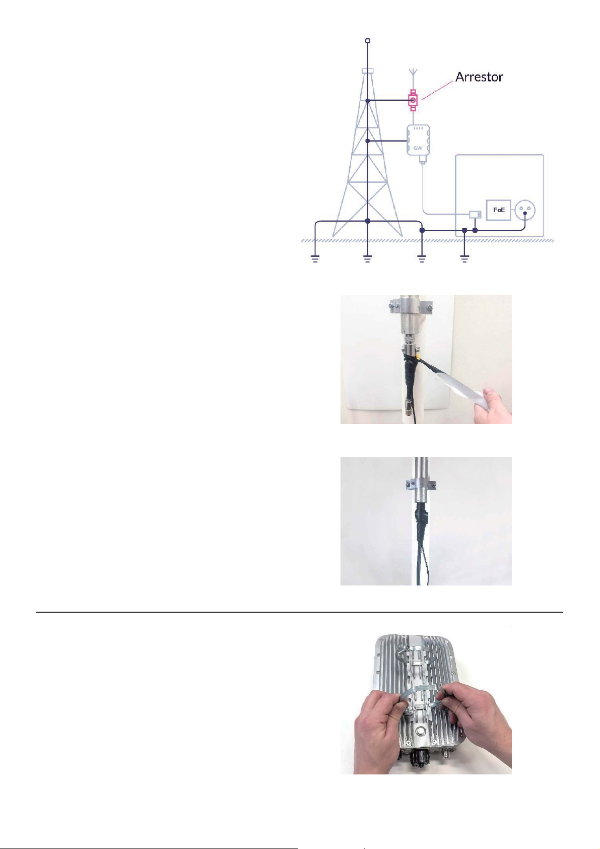
5.2 Groundingɉ
⚠
Grounding all components
static electricity in the cables
for grounding diagram.
b
● Install the clamps that will attach theb
b
is extremely important for
protection against lightning
strikes and dissipation of
and equipment.
Please see drawing below
5.3 Mount Antennaɉ
antenna to the towerb
b
everynet.com 14ɉ
Page 15
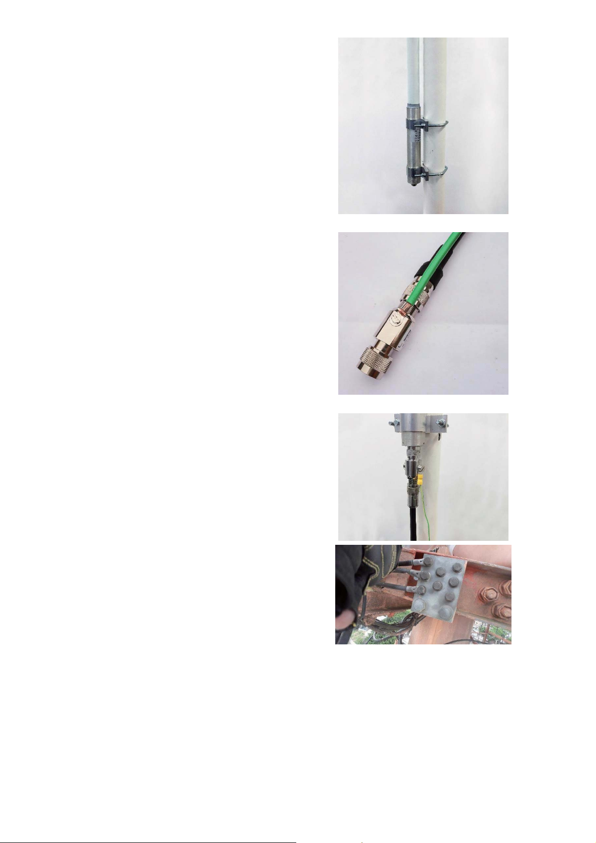
● Attach the antenna on the tower tob
manufacturer specificationsb
b
● Connect one grounding strap to the lightningb
●
●
Tightening of RF connectors must be made byb
b
● Connect lighting protection and groundingb
b
protector. Connect the other end to theb
grounding point of the tower. Penetrox orb
anti-oxidation agent must be used whenb
attaching grounding strap to towerb
grounding pointb
b
Connect lightning arrestor to antennab
Hand tighten RF cable into the antennab
NOTE: Do not use a wrench or pliers as thisb
will damage the gateway or connector.b
hand.b
strap to the grounding point on the tower.b
b
NOTE: It is not allowed to ground a lightingb
protector directly to the tower structures.b
b
b
b
everynet.com 15ɉ
Page 16
b
b
● Completely wrap all RF cable connectionsb
and N connectors with 3M Mastic Tape then
b
at least two layers of Super 33+ sealing tape.b
bottom of sealing area (one at top and one atb
b
● Verify weatherproofing on all cableb
b
Mounting gateway to tower poleb
●
●
b
Two zip tie wraps shall be used for top andb
bottom of connector).b
connectionsb
b
b
b
5.4 Mount Gatewayɉ
b
Insert two steel ring clamps through theb
gatewayb
Use metal ties onlyb
b
everynet.com 16ɉ
Page 17
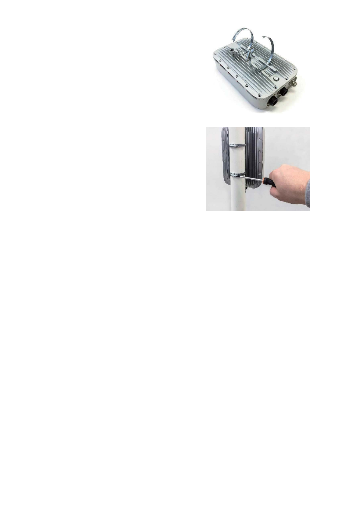
b
● Mount gateway on the tower pole. Tightenb
steel ring clampsbb
b
b
everynet.com 17ɉ
Page 18
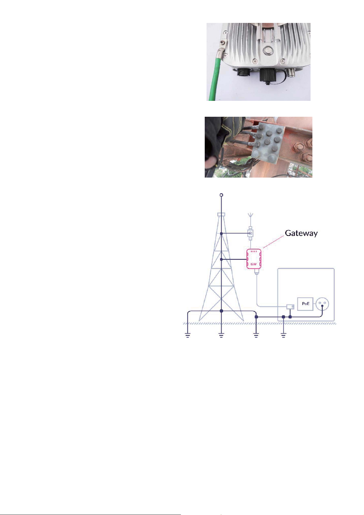
● Connect the second grounding strap to theb
ground stud on the gateway. Connectb
●
IMPORTANT: It is not permitted to ground theb
gateway directly to the tower structures.
opposite end to the grounding point of theb
tower.bb
Penetrox or anti-oxidation agent must beb
used when attaching grounding strap tob
tower grounding pointb
b
b
bb
everynet.com 18ɉ
Page 19
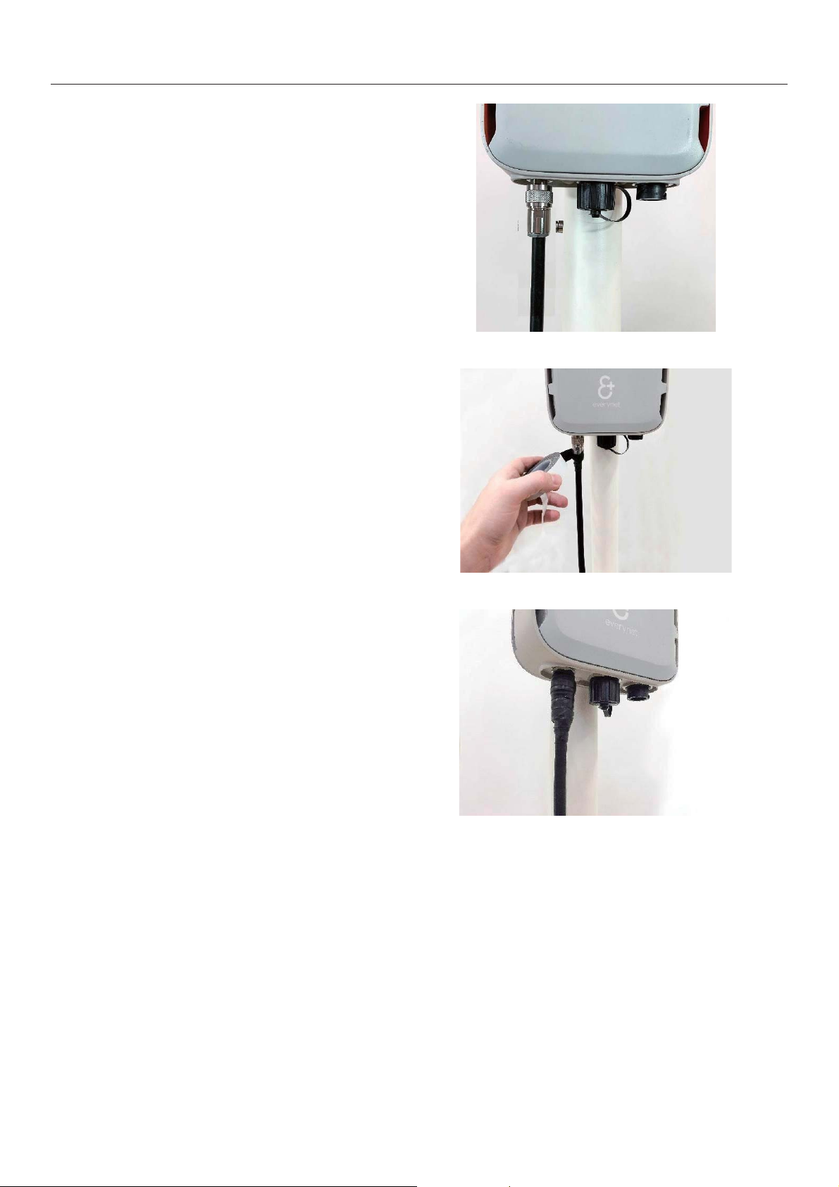
5.5 Connect RF jumper cable to the gatewayɉ
● Attach the RF jumper cable to the gatewayb
IMPORTANT: Do not use a wrench or pliers asb
b
b
●
and N connectors with 3M Mastic Tape thenb
at least two layers of Super 33+ sealing tape.b
bottom of sealing area (one at top and one atb
bb
this will damage the gateway and connector.b
Tightening of RF connectors must be made by
handb
b
Completely wrap all RF cable connectionsb
Two zip tie wraps shall be used for top andb
b
bottom of connector).b
b
b
everynet.com 19ɉ
Page 20
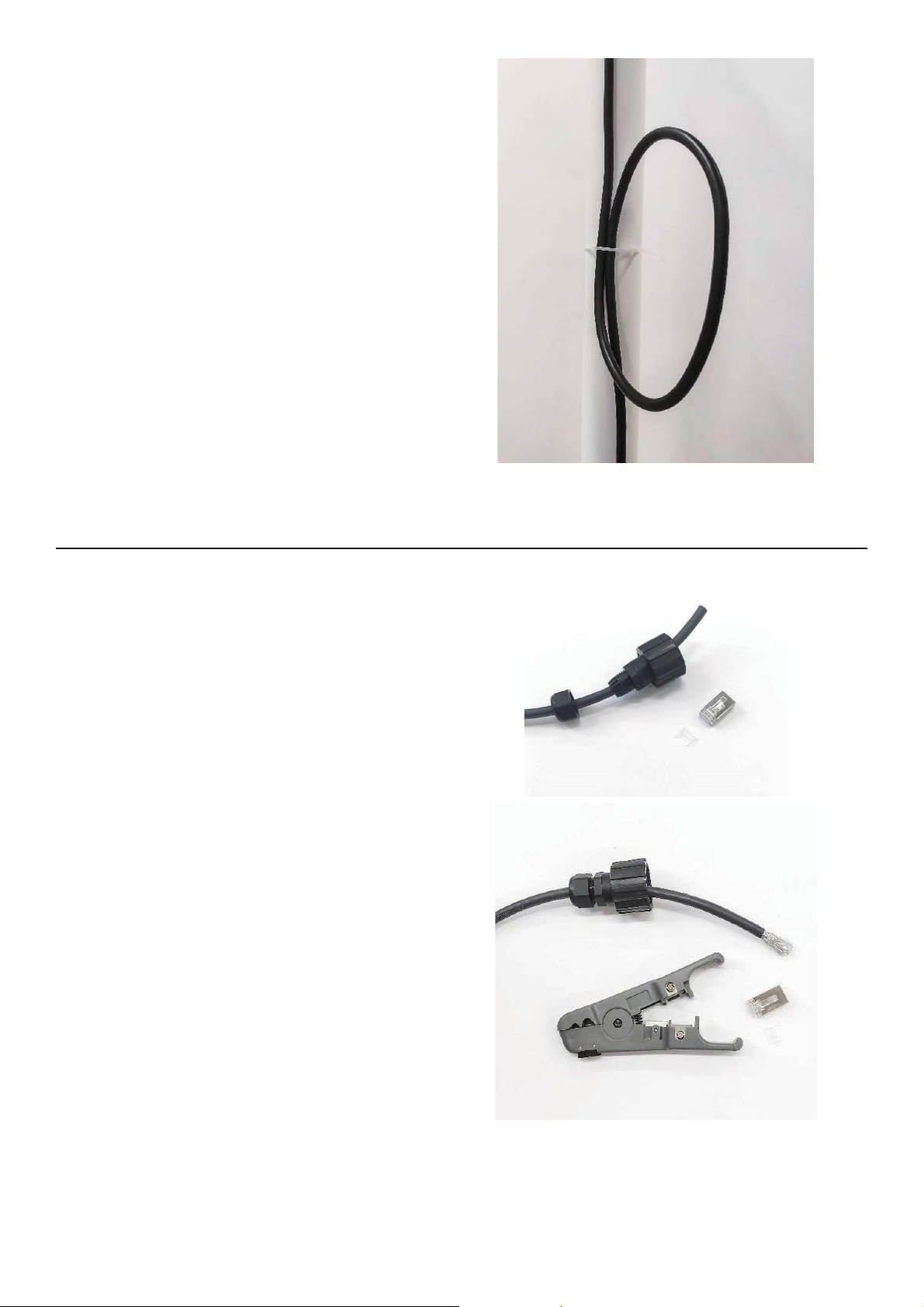
● Fix the RF jumper cable in the tower withb
cable ties leaving two laps to spare for futureb
relocation of the gatewayb
b
b
b
● Insert the CONEC housing over the ethernetb
b
● Etch 4 cm of PVC cover with the wireb
b
●
●
● Carefully fold the aluminum shield to exposeb
b
b
b
b
NOTE: Do not bend the RF cable to less than 4
cm radius. Kinking coaxial cable will damageb
the cable and cause poor radio performance.b
b
IMPORTANT: DO NOT use metal zip ties tob
secure the cable as it will significantly reduce
the performance and could damage theb
gateway. Use only plastic ties.b
b
5.6 Ethernet to gateway cable connectionɉ
cableb
stripper. Carefully remove the braided cable
shield jacket.b
Use a TOUGHCable connector to measureb
the exposed cable needed (approximatelyb
22mm) and trim accordingly.b
Remove the shielding from the cable.b
the transparent plastic wrapping around the
twisted pair cable.b
Be careful when trimming the braided cable to
avoid cutting the shield and ground wire.b
everynet.com 20ɉ
Page 21
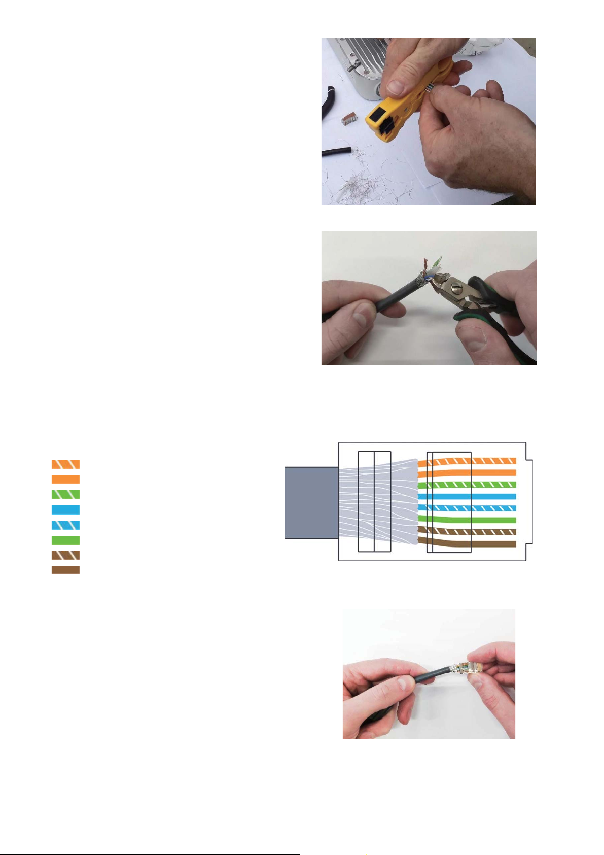
● Cut the clear plastic around the twisted pairb
cable.b
●
b
b
● Put the wires in orderb
b
White-Orangeb
b
Orangeb
b
White-Greenb
b
Blueb
b
White-Blueb
b
Greenb
b
White-Brownb
b
Brownb
b
b
● Place the wires in the correct order, leaveb
half the foil to connect the shield to the plug.b
●
b
●
Use wire cutters to cut off the exposed part
of the plastic.b
Insert the wires carefully into the RJ45b
connector and press firmly to seat the wires
into fully into the plug.bb
Crimp completely and double-check cableb
wiringb
b
b
everynet.com 21ɉ
Page 22
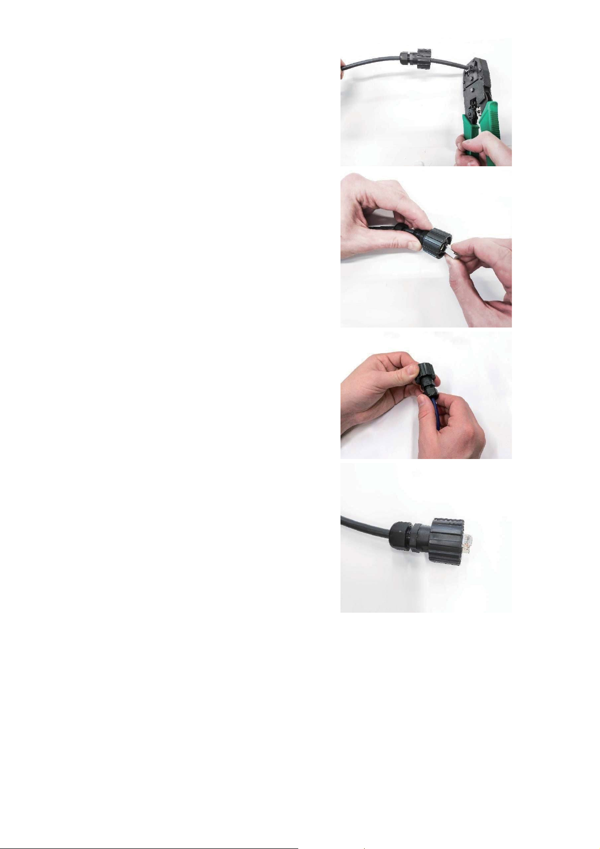
● Insert connector into the CONEC housingb
and screw nut.b
b
everynet.com 22ɉ
Page 23
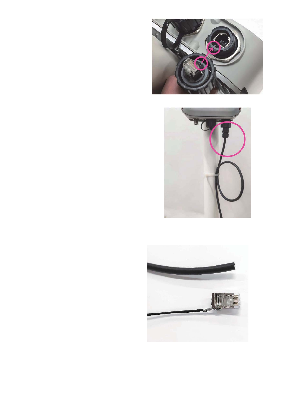
● Plug the network cable into the gateway.bb
b
Check the necessary cable length, alwaysb
●
●
b
● Fix the network cable in the tower with cableb
b
b
b
● Use TC-GND for PoE injector side ofb
●
b
●
b
●
●
b
b
NOTE: Verify CONEC and RJ45 keys areb
aligned before insertingb
remembering to leave two laps to spare forb
future relocation of the gateway.b
b
Make two laps on the network cable forb
leftovers for future relocations.b
Use plastic cable ties (model 20.32cm) to fix
the cable.b
b
b
ties (model 35.56cm) every 2 metersb
5.7 Ethernet to PoE adapter cable connectionɉ
ethernet cableb
b
Etch 4 cm of PVC cover with theb
wire stripper. Carefully remove the
braided cable shield jacket.b
Use a TOUGHCable connector tob
measure the exposed cable needed
(approximately 22mm) and trimb
accordingly.b
Remove the shielding from theb
cable.b
Carefully fold the aluminum shieldb
to expose the transparent plasticb
wrapping around the twisted pairb
cable.b
everynet.com 23ɉ
Page 24
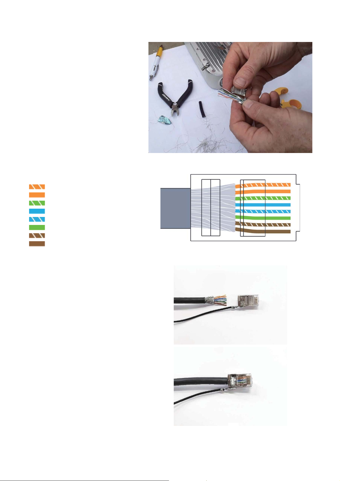
● Cut the clear plastic around theb
twisted pair cable.b
●
b
b
b
● Put the wires in orderb
b
White-Orangeb
b
Orangeb
b
White-Greenb
b
Blueb
b
White-Blueb
b
Greenb
b
White-Brownb
b
Brownb
b
b
● Place the wires in the correct order,b
●
seat the wires into fully into the plug.bb
●
b
b
Use wire cutters to cut off theb
exposed part of the plastic.b
leave half the foil to connect theb
shield to the plug.b
Insert the wires carefully into theb
RJ45 connector and press firmly tob
Crimp completely and double-check
cable wiringb
everynet.com 24ɉ
Page 25
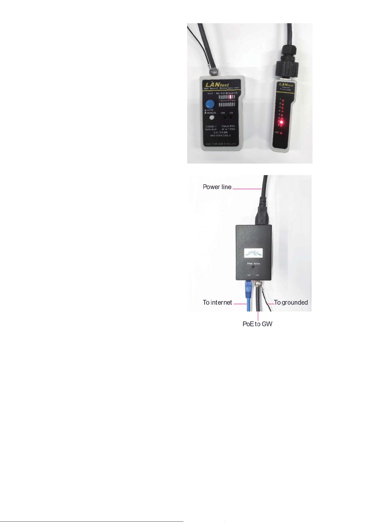
IMPORTANT: Always verify allb
ethernet connections with cable mapb
● Connect network cable POE port ofb
●
b
● Connect PoE power cable to 3 pin ACb
b
tool and continuity testerb
PoE- Ubiquiti PoE 48v-24w injectorb
b
Connect ethernet round wire to the
tower according to the scheme.b
b
power jackb
b
b
everynet.com 25ɉ
Page 26
b
b
b
ground pin must be connected to a
grounded through the AC ground pin ofb
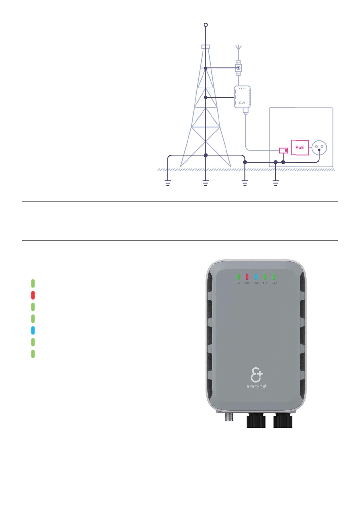
● Check that the connecting lights are in the
b
LTE – green b
b
ETH – red or greenb
b
PWR – green or blue
(blue means that the battery is charging)
b
GPS – green
b
LORA – greenb
PoE injector MUST have a detachable 3
pin power cord which contains anb
integral safety ground wire. Thisb
b
grounded safety outlet.b
Ethernet cable shield MUST also beb
the PoE power cable.b
5.8 Verify all the connectors are correctɉ
b
5.9 Check LEDs indicationɉ
correct colors.
everynet.com 26ɉ
Page 27
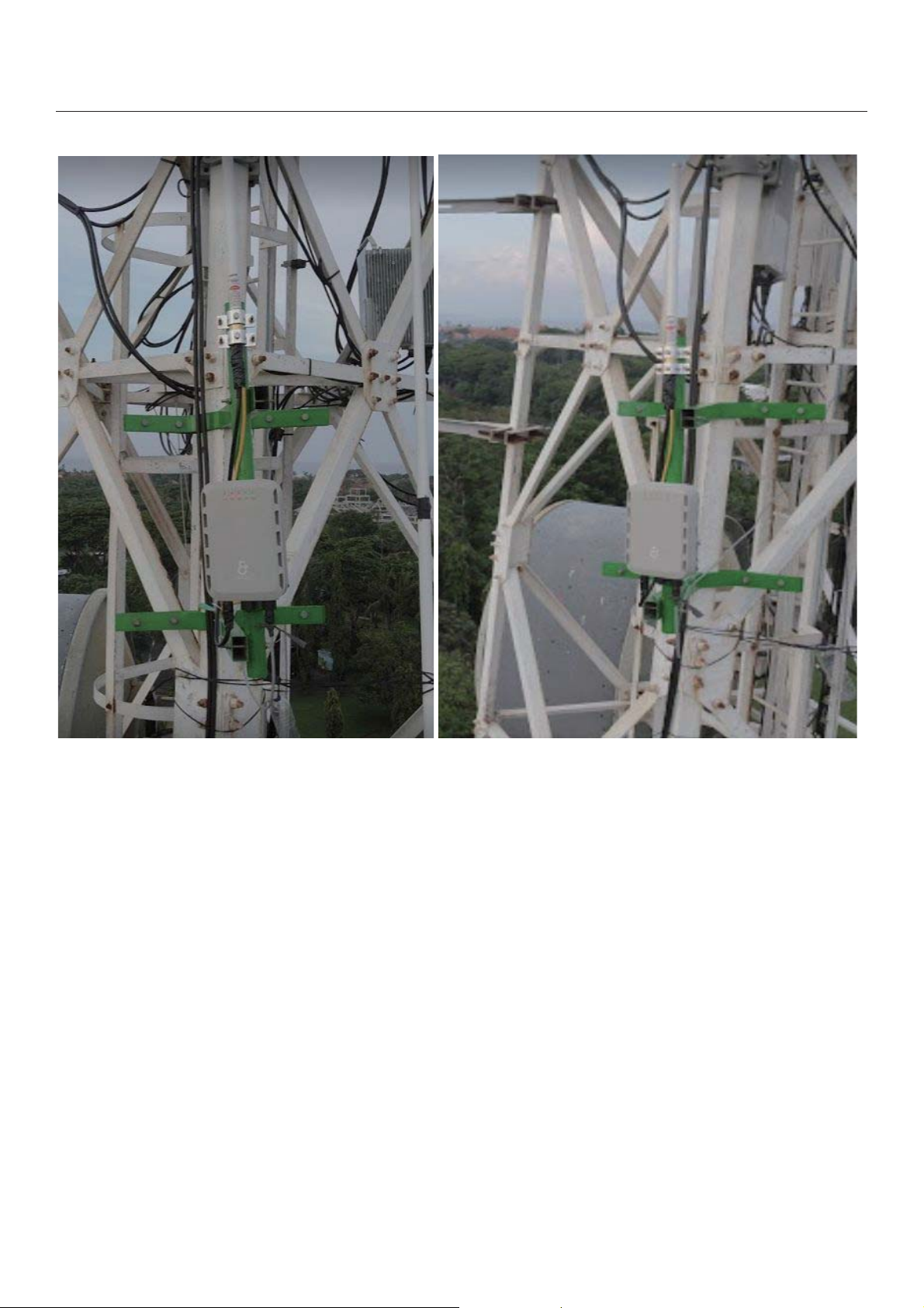
5.10 Verify gateway is affixed securely on the towerɉ
b
everynet.com 27ɉ
Page 28

FCCɉ part 8
FCC Caution:
Any changes or modifications not expressly approved by the party responsible forb
compliance could void the user's authority to operate this equipment.b
This device complies with Part 15 of the FCC Rules. Operation is subject to the following twob
conditions:b
(1) This device may not cause harmful interference, andb
(2) this device must accept any interference received, including interference that may causeb
undesired operation.b
This device and its antenna(s) must not be co-located or operating in conjunction with any otherb
antenna or transmitter.b
NOTE:bb
This equipment has been tested and found to comply with the limits for a Class B digitalb
device, pursuant to Part 15 of the FCC Rules.bb
These limits are designed to provide reasonable protection against harmful interferenceb
in a residential installation. This equipment generates, uses and can radiate radio frequency energyb
and, if not installed and used in accordance with the instructions,b
may cause harmful interference to radio communications.bb
However, there is no guarantee that interference will not occur in a particular installation.b
If this equipment does cause harmful interference to radio or television reception,b
which can be determined by turning the equipment off and on, the user is encouraged tobb
try to correct the interference by one or more of the following measures:b
-- Reorient or relocate the receiving antenna.b
-- Increase the separation between the equipment and receiver.b
-- Connect the equipment into an outlet on a circuit different from that to which theb
receiver is connected.b
-- Consult the dealer or an experienced radio/TV technician for help.b
To maintain compliance with FCC’s RF Exposure guidelines, The 20cm is the minimum distance thatb
has to be maintained between your body and the device.b
everynet.com 30ɉ
1. Scan QR code
2. The label and text will appear below
1. Scan QR code
2. The label and text will appear below
 Loading...