

Page 1

GENERAL
INSTAL
GUIDE
LATION
www.EverWarm.net
Page 2
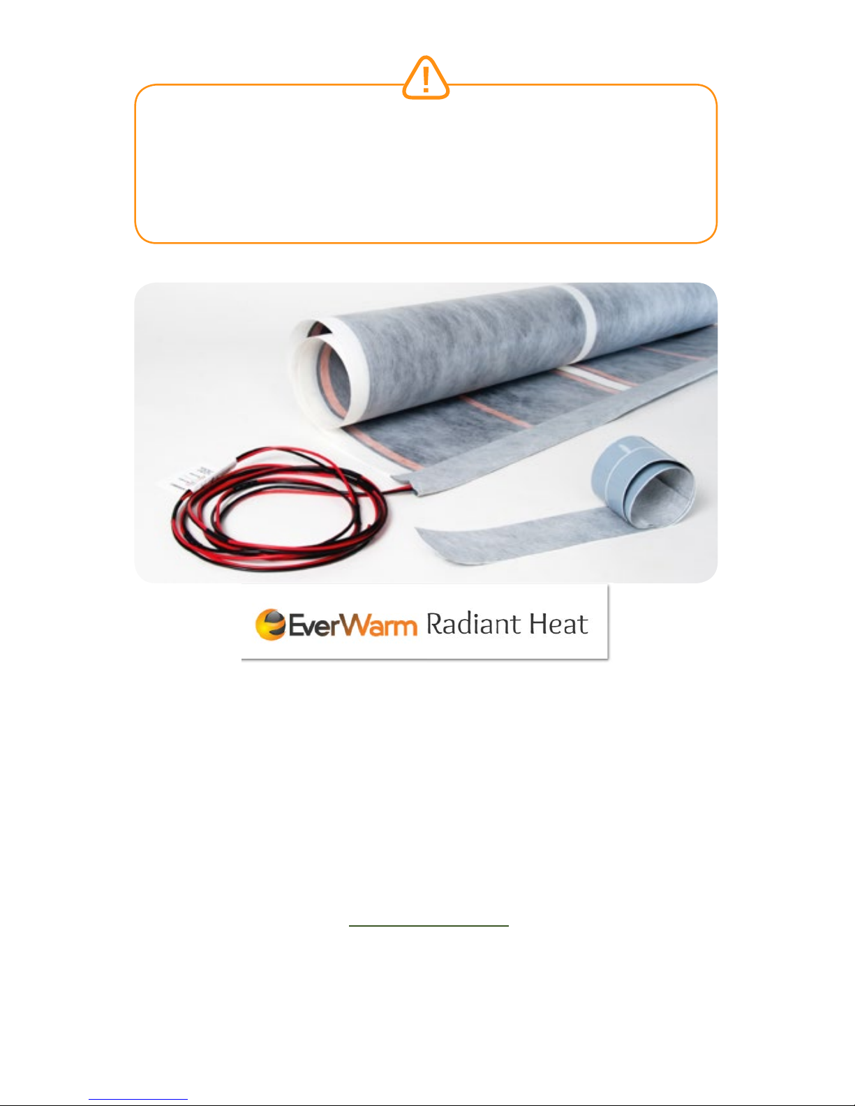
THIS PRODUCT SHOULD ONLY BE INSTALLED BY QUALIFIED
PERSONNEL WHO ARE FAMILIAR WITH THE CONSTRUCTION AND
OPERATION OF THE APPARATUS AND ANY RISKS INVOLVED.
READ ALL INFORMATION PROVIDED IN THIS GUIDE BEFORE
ATTEMPTING TO INSTALL THIS PRODUCT.
FOR PART NUMBERS: CHK-15-120, CHK-25-120, CHF-50, CHK-50-120,
CHK-50-240, CHF-100, CHK-100-120, CHK-100-240, CHF-200,
CHK-200-240, CHF-550
THE DOCUMENTATION PROVIDED HEREIN PERTAINS SOLEY TO THE
USE AND INSTALLATION OF EverWarm Radiant Heat FILM, EverWarm
RADIANT FLOORS, OEM ACCESSORIES, AND PRODUCTS
PRODUCED BY CarbonicHeat CORPORATION. SUBJECT MATTER
AND SPECIFICATIONS ARE SUBJECT TO CHANGE.
For updated information on our products please refer to our website
www.EverWarm.net
855.558.5200
416 South Main Street, Suite B-2 Hailey, ID 83333, USA
VERSION 11
Page 3

TABLE OF CONTENTS
SECTION 1: GENERAL NOTES AND INFORMATION .............4-10
SECTION 2: TOOLS REQUIRED FOR INSTALLATION ............... 11
SECTION 3: INSTALLATION GUIDELINES ........................ 12-20
SUBFLOOR PREPARATIONS ..................... 12
TILE ................................................. 13-16
LAMINATE ............................................ 17
WOOD FLOOR ....................................... 18
CARPET ................................................ 19
LINOLEUM AND VINYL ........................... 20
SECTION 4: INSTALLING HEATING FILM ......................... 21-23
SECTION 5: GENERAL INSTALLATION INSTRUCTIONS ...... 24-32
LAYOU T................................................24
INSTALLING HEATING FILM ......................26
ATTACHING HARNESS .............................27
TESTING CONNECTIONS AND
HEATING FILM; MEASURING OHM’S ..........28
OHM’S READINESS TEST .........................29
APPLYING EDGE SEALING TAPE................29
INSTALLING FLOOR SENSOR .................... 31
ELECTRICAL REQUIREMENTS ...................32
ATTACHIN G T H ERMOSTAT .......................32
SECTION 6: 120 VOLT CONFIGURATION ............................. 33
SECTION 7: 240 VOLT CONFIGURATION ............................ 35
SECTION 8: MULTIPLE ZONES ......................................... 37
SECTION 9: TROUBLESHOOTING ...................................... 38
SECTION 10: WARRANTY ............................................... 39
SECTION 11: NOTES ....................................................... 40
Page 4

PAGE 41
SECTION 1
GENERAL NOTES & INFORMATION
READ ALL INFORMATION PROVIDED IN THIS GUIDE
BEFORE ATTEMPTING TO INSTALL THIS PRODUCT
The installation of this heating product must be in accordance with both the
manufacturer’s instructions, and the regulations of the authori
ty having
jurisdiction. Failure to do so will result in a voided warranty.
Caution must be taken to guard against risk of electric shock, fire, and bodily
injury during installation of this product.
All floors & subfloors should be prepared in accordance to ANSI & TCNA
specifications. All masonry, adhesives, moisture barriers, and bonding
agents used in the installation must be fully cured (per the manufacturer’s
recommendations - but not less than 28 days) prior to energizing the product
for the first time. All components must be recognized and rated for their use.
NEVER OVERLAP, LAYER, OR STACK THE HEATING FILM ON TOP OF
ANOTHER PIECE OF THE HEATING FILM.
The installation of this heating product must always be connected to a
DEDICATED electrical circuit.
The system shall be installed with a disconnecting means.
The system should always be disconnected from its power source during
service. This includes service to the thermostat.
All systems MUST be installed with a GFCI compliant thermostat or breaker.
The supply wire or terminals cannot be repaired. If the wire or terminal is
damaged, it must be replaced.
The National Electric Code does not allow the placement of nails, staples, or
other fasteners through the carbon heating or copper bus bar zones.
If a nail or staple is accidentally placed through this area, they must be
removed and securely taped shut.
EverWarm Radiant Heat
Page 5

EverWarm Radiant Floors
PAGE 5
SECTION 1
1.DO NOT install the Heating Film under large appliances such as
refrigerators, freezers, washers, or dryers (as the heat can be detrimental to
the operation of the appliances).
2.DO NOT install the Heating Film under large, flat-bottomed furniture, built
in cabinetry, vanities, or in any application in which air circulation over the
floor is limited (as the heat can be detrimental to the products).
3.DO NOT install the Heating Film between floor joists under the sub- floor,
in wall cavities, or in ceilings.
4.DO NOT install the Heating Film in food pantries or under floating vanities
(as the heat can be detrimental to the products stored in these areas).
5.DO NOT overlap, layer, or stack the Heating Film on top of another piece
of the Heating Film.
6.DO NOT install the Heating Film over pre-existing linoleum, PVC, or vinyl
floor coverings. (All must be removed, including all pre-existing adhesive,
prior to the installation of the Heating Film).
Prior to installation please consult the local codes. If any of the information in
this guide is not consistent with local codes, the local codes should be
followed. However, electrical wiring is required to be run from a circuit
breaker or other electrical circuit to the control. It is recommended that a
qualified electrician perform these installation steps. Please be aware that
local codes may require that this product and/or the control to
be installed by
an electrician.
Operating the system without a floor covering in place will void the warranty
of the product.
ALL REQUIRED INSPECTIONS MUST BE COMPLETED BEFORE COVERING THE
HEATING FILM INSTALLATION.
Page 6

PAGE 61
SECTION 1
SPECIFICATIONS FOR HEATING FILM:
Applications: Indoor floor heating.
Listings: UL Listed for U.S. and Canada under
UL 1693 and CAN/CSA C22.2 No.
130.2-93, File No. 20140325E465902, ETL 4007353, CE 120509,
TUV K5140/E112
Controls:Heating Film must be controlled by a
CarbonicHeat approved direct voltage
Floor heat-sensing thermostat.
Voltage:120 VAC Max 100 sq. ft. (9.29 sq.m)
50/60hz,
240 VAC Max 200 sq. ft. (18.58 sq.m)
50/60 Hz
Watts: 15 W/sq. ft. (51 BTU/sq. ft.), 166.1 W/sq.m
Maximum circuit load: 15 Amp
Maximum circuit overload protection: 20 Amp breaker GFCI: (Ground Fault
Circuit Interrupter) required for each circuit (included in the thermostat control).
Maximum bend radius: Not to exceed 90 degrees. Do not crease Heating Film.
Maximum exposure temperature: (Continuous and storage) 150ºF (65.5ºC)
Minimum installation temperature: 50ºF (10ºC)
SKILL REQUIREMENTS:
Installation must be performed by qualified persons, in accordance with local
codes, ANSI/NFPA 70 (NEC Article 424), and CEC Part 1 Section 62 where
applicable. All electrical work must be installed in accordance with Article 424 Part
IX of the National Electric Code (NEC) ANSI/NFPA 70. “STATEMENT OF
NATIONAL ELECTRIC CODE PRODUCT COMPLIANCE (NEC). This product
from EverWarm Radiant Heat™ Corporation is compliant to Article 424, Part
IX of the National Electric Code (NEC), “Electric Radiant Heating Sheets and
Heating Sheet Sets” and as a Heating Sheet Set. Electrical installations must use
a Terminal Junction Assembly manufactured only by CarbonicHeat™ Corporation
per NEC 424.96 (2)”.
THANK YOU FOR SELECTING
EverWarm Radiant Heat®
This informational manual is provided as a guide to installing
EverWarm Radiant Heat Film, including design suggestions,
installation steps, precautions, limitations, and floor covering
guidelines.
EverWarm Radiant Heat
Page 7
EverWarm Radiant Floors
PAGE 7
SECTION 1
UNDERSTANDING EverWarm Radiant Heat FILM
Carbonic Heating Film is a revolutionary solution to today’s radiant floor
heating applications. The Heating Film is manufactured to make radiant floor
heating more readily available, far more adaptable for unique applications
and designs, and far easier to install than many other radiant floor products.
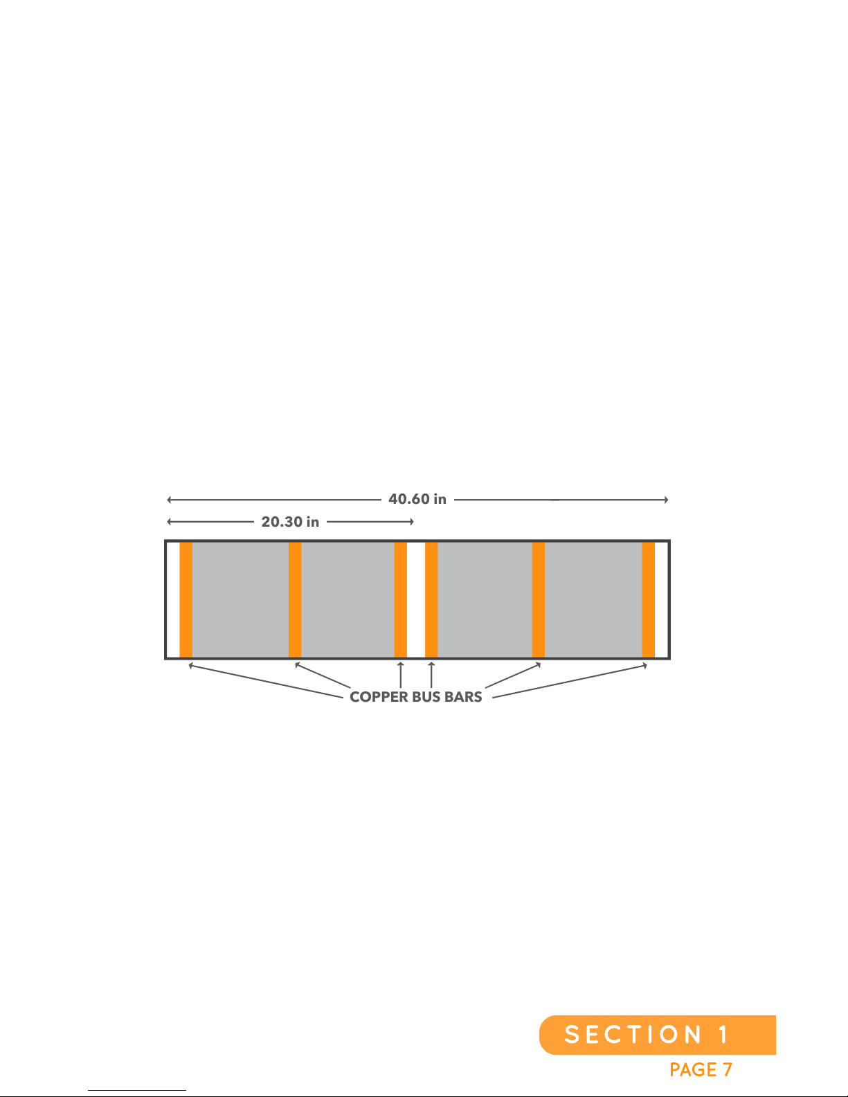
Carbonic Heating Film is 40.6 inches wide (but can be cut to half the width if
desired for certain applications) and is available in many lengths to
accommodate your specific needs. The Heating Film may be cut to any
length with the use of scissors, a razor knife, or other cutting instruments. It
can also be cut at any angle needed for each application, including the
cutting of a hole for an electrical outlet, toilet flange, or floor register.
There are a few things to know about the structure of the Heating Film.
Electrical current-conducting copper bus bars run down the length of the
Heating Film (2 bus bars are required to create heat - see drawing). Should a
copper bus bar be cut during the installation of the product, you may repair it
by either adding an “Adder” at the end or by installing a “Jumper” at the cut
point. More about these later.
Under no circumstances should the active areas (gray) of the Heating Film
be allowed to overlap itself or an adjacent piece of the Heating Film. The
product includes three areas (the two white outer edge strips and the white
center “Cut Line” strip) suitable for nailing and stapling to sub-floor, if
deemed necessary, for the designed installation of the product. These strips
are non-conductive and non-heat generating. All fasteners used to secure
the Heating Film to the sub-floor (excluding adhesives), including staples or
nails that are to be used, must only be placed through these designated
areas and not in the active carbon (gray) heating areas. Failure to do so will
cause problems with the system and/or damage the Heating Film and
associated areas including the building structure. The Heating Film can be
installed with either side facing up.
40.60 in
COPPER BUS BARS
20.30 in
Page 8
PAGE 81
SECTION 1
EXPECTED FLOOR TEMPERATURE
Heating performance is never guaranteed. EverWarm Radiant Heat is
designed to deliver 15 W/sq. ft., with an average attainable temperature
between 75°F (23.9°C) and 104°F (40°C), depending upon the subfloor, the
layers of materials included in the floor installation, and the type of flooring
used. The attainable floor temperature is dependent on how well the floor is
insulated, the temperature of the floor prior to start up, and the overall
thermal drain of the floor mass. Insulation is recommended under the
Heating Film for best performance.
WIRING ASSEMBLIES
Since this is a high voltage product, a connection system is required for
power. A “Harness” is used to connect the Heating Film to a thermostat and
power supply, and a Harness is used to connect multiple pieces of Heating
Film in certain installations. EverWarm Radiant Heat Harnesses, Adders,
and Jumpers are manufactured for either 120V or 240V applications. The
wiring assemblies are designed for maximum efficiency and will work well
for almost any layout requirements. It is important to note that there are six
crimping terminals per sheet for the 120v Harness and four crimping
terminals per sheet for the 240v Harness.
THERE ARE THREE TYPES OF WIRING ASSEMBLIES:
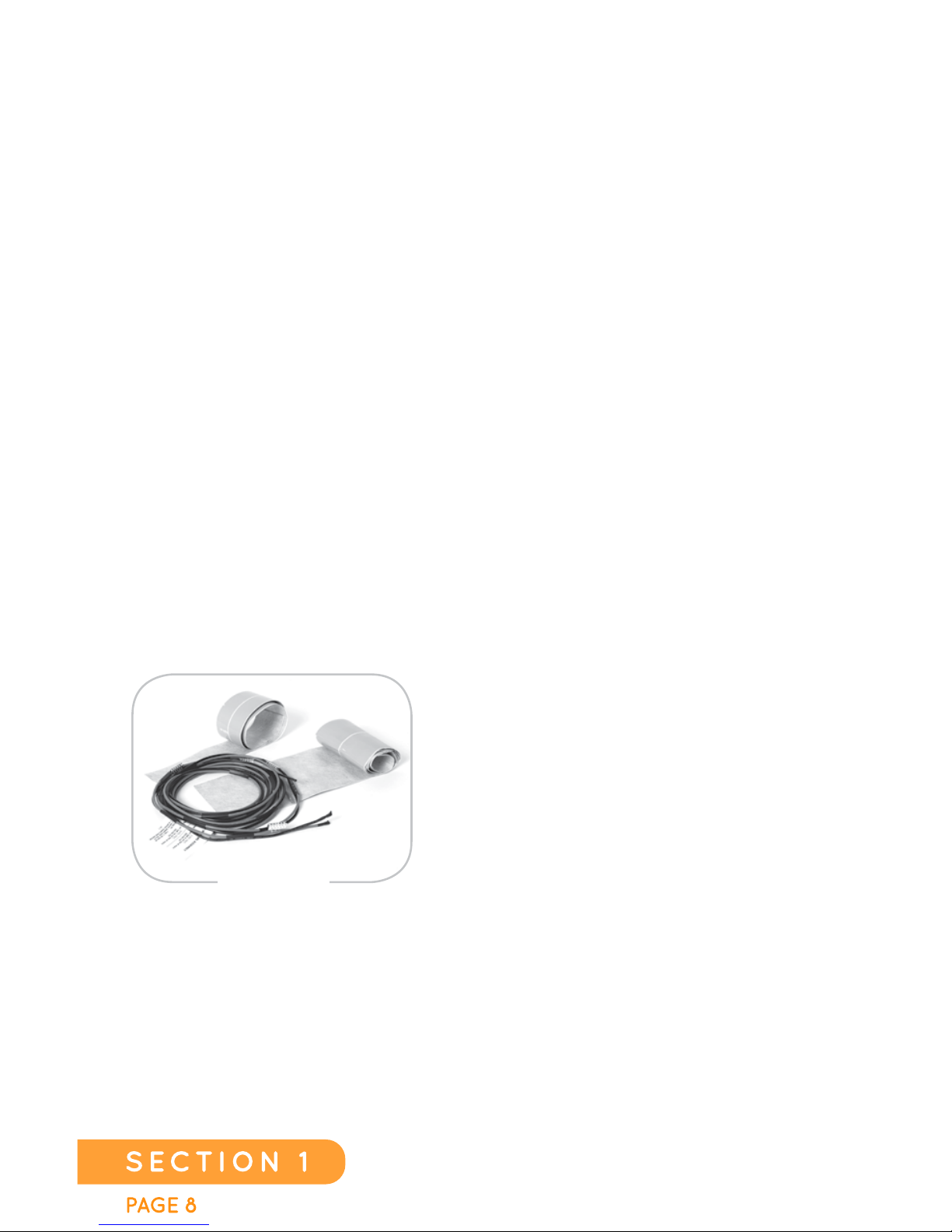
1. Harnesses (J, J2, J3, J4): Harnesses
are used for connecting sheet(s) of Heating
Film with a 12 foot long “cold lead” that is
run to a thermostat, or to connect to
another sheet of Heating Film. Harnesses
are available in 120 volt and 240 volt
configurations. For a single panel 120 volt
application a “J-120” (J indicates one sheet,
and 120 is the voltage) would be required.
For a dual sheet would be required.
For a dual sheet configuration using 240 volts a “J2-240” (J2 indicates two
sheets, and 240 is the voltage) would be required. Connections for a three
sheet system would require a J3. A J4 Harness will connect four sheets of
Heating Film together. If there are three and a half sheets needed, a J4 can
be used by trimming off the unused portion of the Harness.
HARNESS
EverWarm Radiant Heat
Page 9
EverWarm Radiant Floors
PAGE 9
SECTION 1
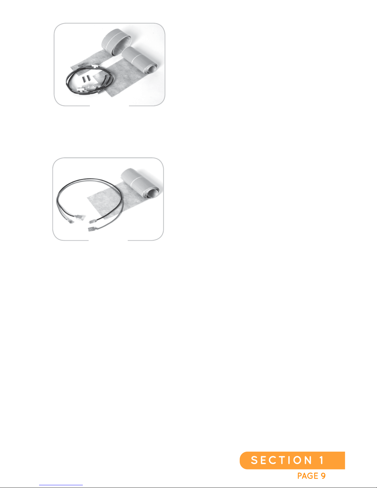
2. Adders (A, A2, A3, A4): Adders are
used to attach one sheet of Heating Film
to another, when a thermostat cold lead
connection is not required. Adders are
available in 120 volt and 240 volt
configurations. To add a single sheet
of Heating Film to a 120 volt system, an
“A-120” (A indicates one additional
sheet, 120 indicates the voltage) would
be required. To add two sheets to an
existing sheet, use an A2. To add three sheets, an A3 will be required.
An A4 will connect up to four sheets to an existing sheet or sheet set.
3. Jumper (JP-60): A Jumper can be
used to reconnect a copper bus bar if it
has been cut for completion of the
layout. The Jumper is sixty (60”) inches
in length and can be used on both 120
volt and 240 volt systems. They are
helpful for going through door ways,
around corners, around posts, and
around columns. Jumpers can also be
used around cut outs for floor ports
such as receptacles, registers, and floor ports.
ADDER
JUMPER
Page 10
PAGE 101
SECTION 1
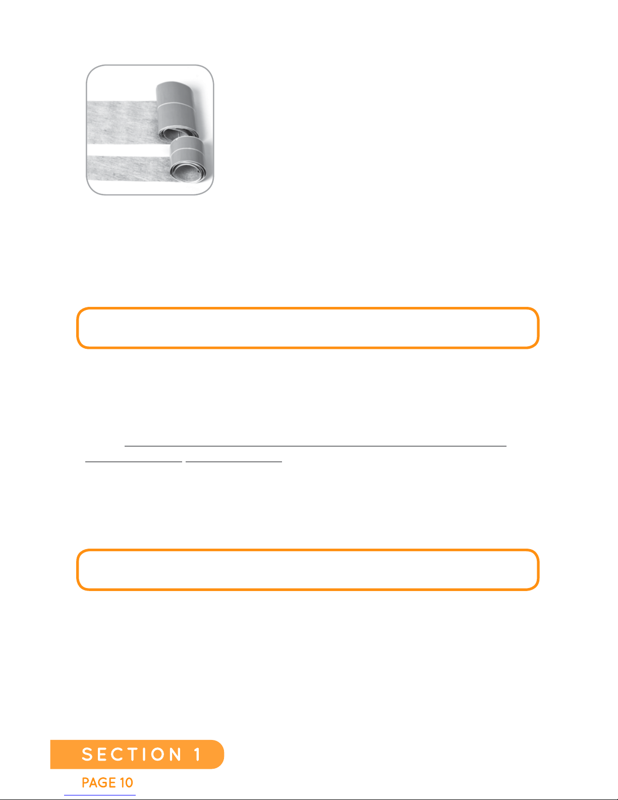
EDGE SEALING TAPE
It is critical to seal any cut that is made to the gray
area of the Heating Film. The Edge Sealing Tape
comes in one length (42 inches), but in two
different widths, 4.8 inches wide and 2.4 inches
wide. The wider Edge Sealing Tape (4.8 inches
wide) is used to seal the edge of the Heating Film
to which the wiring Harness, or Adder is attached.
The narrower Edge Sealing Tape (2.4 inches wide)
is used to seal any cut edges where there is no
attached wiring Harness, Adder, or any other cuts (including holes cut in
between the copper bus bars) that have been made to the Heating Film during
the installation process. The Edge Sealing Tape is a highly-adhesive
fleece-backed butyl tape. The fleece backing that is the same as that used on
EverWarm Radiant Heat Film, making the Edge Sealing Tape compatible with
all types of adhesives.
REMEMBER: THE EDGE SEALING TAPE MUST BE USED ON ANY GRAY EDGE,
OR GRAY AREA OF THE HEATING FILM THAT HAS BEEN CUT.
THERMOSTATS
EverWarm Radiant Heat offers a variety of direct line voltage thermostats in
both programmable and non-programmable models. All EverWarm Radiant
Heat thermostats in the United States are GFCI-protected (required by the
NEC). Each thermostat includes a floor sensor, which EverWarm Radiant
Heat requires for each installation. Each thermostat senses both ambient air
and floor temperatures, enabling installers to set the floor temperature to the
flooring manufacturer’s desired set point, along with maximizing the potential
comfort of the room’s environment. The maximum load allowed on a standard
thermostat is 15 amps. The maximum amount of total Heating Film allowable
per circuit translates to the following:
110-120VAC: 31.25 LINEAR FT = 100 FT2 PER ZONE (1 THERMOSTAT)
220-240VAC: 62.5 LINEAR FT = 200 FT2 PER ZONE (1 THERMOSTAT)
Installations that require a larger amount of Heating Film per thermostat (over
200 square feet per zone) will require the use of a “master” thermostat that
controls a “slave” power unit. Up to 2000 square feet of Heating Film can be
installed and combined using 10 slave units. Up to 10 Slave Units can be
controlled by one Master Thermostat.
EverWarm Radiant Heat
Radiant Floors
Page 11
EverWarm Radiant Floors
PAGE 11
SECTION 2
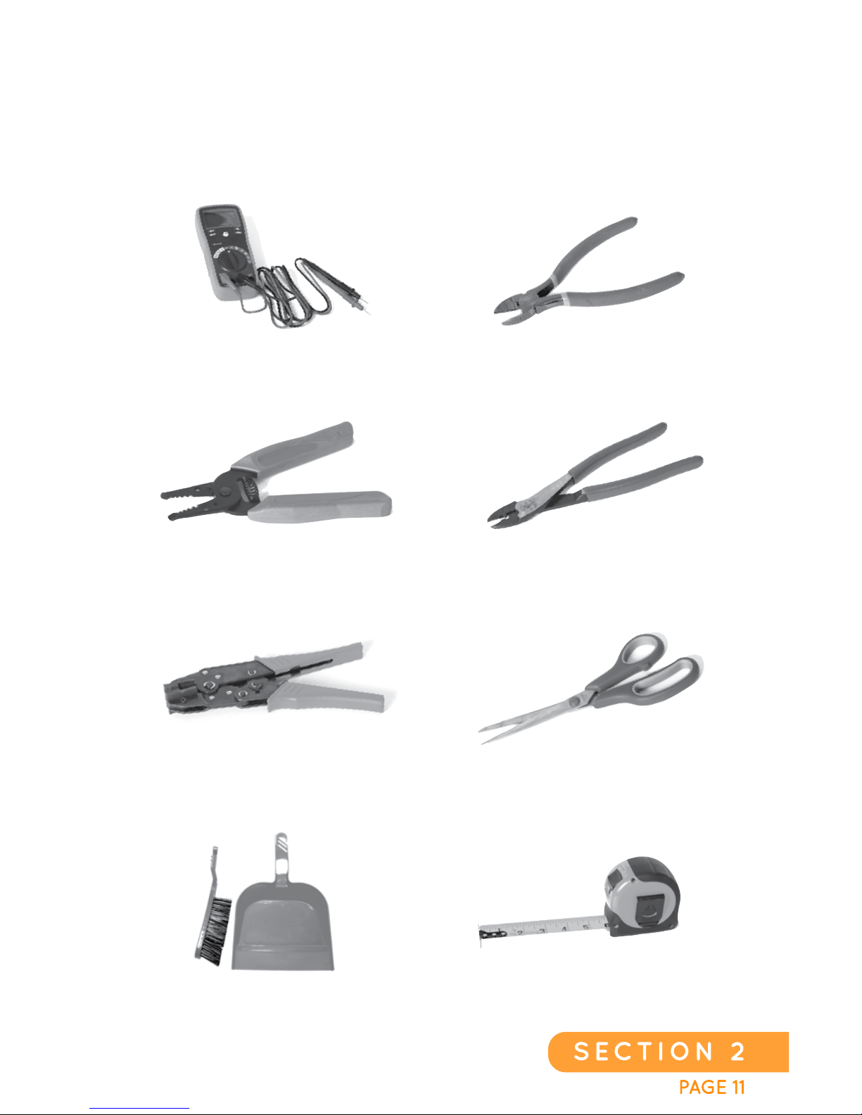
Digital Multi-Meter
Wire Stripper
Wire Cutters
Wire Crimper
Broom/Dust Pan
Scissors
Tape Measure
Flex Heat Crimping Tool
(Pa r t# C HP-01)
TOOLS REQUIRED FOR
INSTALLATION
TOOLS NEEDED WHEN INSTALLING THE
EverWarm Radiant Heat HEATING
SYSTEM
Page 12

PAGE 121
SECTION 3
INSTALLATION GUIDELINES:
THE FOLLOWING SECTION OUTLINES THE PREPARATION
REQUIRED PRIOR TO INSTALLING THE HEATING FILM.
FLOOR PREPARATION
1. Ensure slab or wood sub-floor is structurally sound (follow TCNA
installation guidelines for sub-floor rigidity).
2. Concrete slab must be free of waxy or oily films and curing compounds
(when present, mechanical scarifying is necessary). If these chemicals
are present, water will bead. If the sealer is left on the floor, the mortar
for the tiles won’t adhere. Remove sealer with a floor sander using
medium-grit sandpaper.
3. There should not be any protrusions sticking up from the sub-floor that
could impact or cause damage to the Heating Film such as nails, rebar,
or any other potentially damaging material.
4. Level the floor per TCNA guidelines. Allow the compound to dry
following manufacturer’s recommendations.
5. Mop or sponge the floor with clean water to remove any traces of dust.
6. Make sure the floor is completely dry before installing EverWarm
Radiant Heat Film.
EverWarm Radiant Heat
Page 13
EverWarm Radiant Floors
PAGE 13
SECTION 3
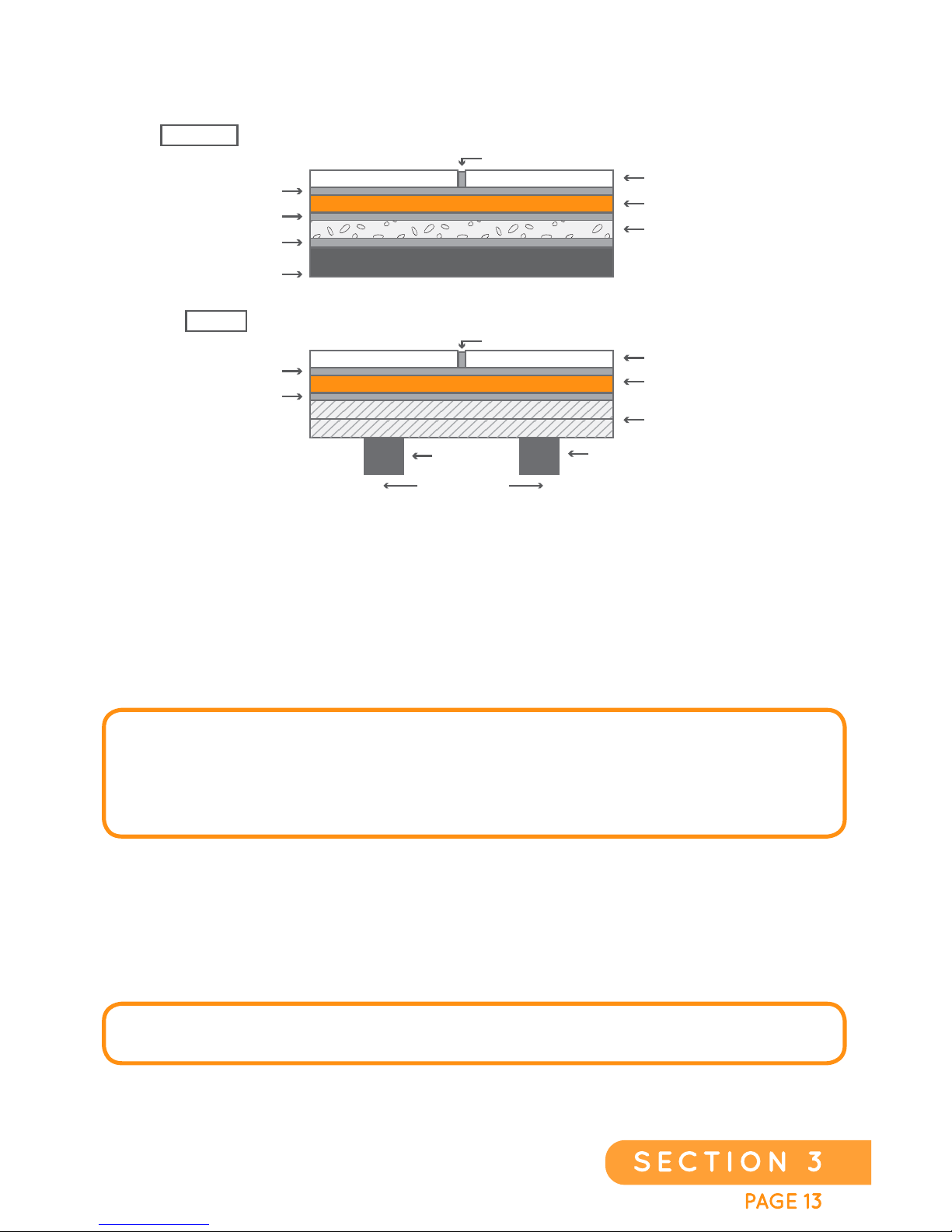
TILE INSTALLATION
INSULATED CONCRETE AND WOOD SUBFLOOR
RH115 A FLOORS, INTERIOR: RADIANT HEAT ON INSULATED CONCRETE, THIN-SET
RH130 FLOORS, INTERIOR: RADIANT HEAT ON WOOD SUBFLOOR, THIN-SET
THIN-SET
THIN-SET
THIN-SET
CONRETE OR
CURED MORTAR BED
TILE / SLATE / STONE
HEATING FILM
1/4” CORK OR 3/16” CERAZORB
GROUT
GROUT
THIN-SET 3/8”
THIN-SET
TILE / SLATE / STONE
HEATING FILM
JOIST
PLYWOOD SUBFLOOR
JOIST
GROUT
16” (406mm) o.c.
1. Prepare the Heating Film according to the steps in the General Installation
Instructions beginning on page #24.
2. Install the tile on top of the Heating Film using an unmodified thin-set mortar
meeting the requirements of ANSI A118.1 to install ceramic and stone tile.
(See notes).
NOTE: EverWarm PRODUCTS, LLC DOES NOT RECOMMEND THE USE OF
MODIFIED THIN-SET MORTARS TO SET TILE OVER THE HEATING FILM BECAUSE
THESE MORTARS MUST AIR-DRY TO CURE PROPERLY. WHEN “SANDWICHED”
BETWEEN TWO IMPERVIOUS LAYERS SUCH AS EverWarm AND PORCELAIN TILE,
DRYING TAKES PLACE VERY SLOWLY THROUGH THE OPEN GROUT JOINTS.
*Exception: Certain moisture-sensitive stones, (e.g., green marble or resinbacked tiles) may require special setting materials. Please consult the stone
supplier for more information. For an acid-resistant covering, use an epoxy
adhesive to set and grout the tile.
FLOOR SENSOR (INCLUDED WITH ALL THERMOSTATS)
MUST BE PROPERLY INSTALLED.
Page 14
PAGE 141
SECTION 3
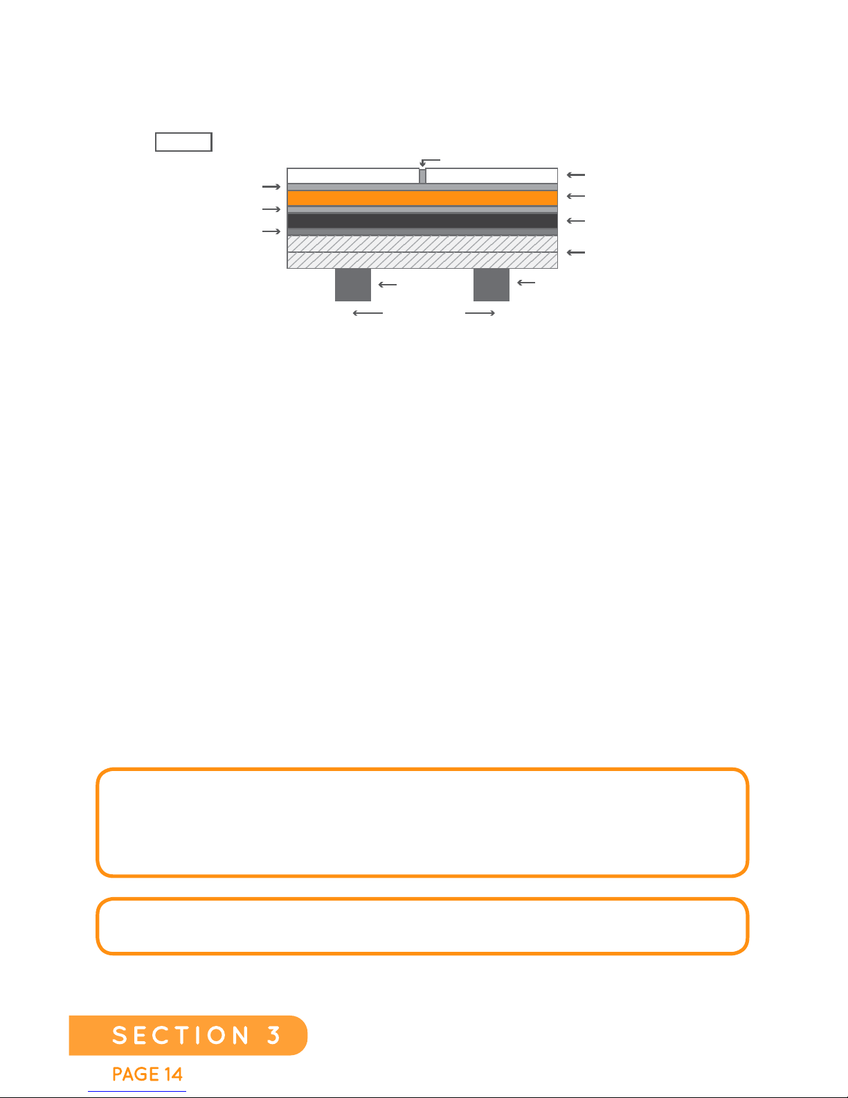
TILE INSTALLATION
WOOD SUBFLOOR WITH BACKER BOARD
1. Install the backer board per the manufacturer’s instructions.
2. There should be no items or protrusions sticking up from the sub-floor
that could impact or cause damage to the Heating Film such as nails,
rebar, or other potentially damaging objects.
3. Prepare the Heating Film according to the steps in the General
Installation Instructions beginning on page #24.
4. While rolling back ½ of the Heating Film at a time, use a
3/16”-1/4” (5-6mm) V-notch trowel to apply thin-set to the floor. Set the
Heating Film onto the thin-set and, using a roller, apply a continuous,
even pressure with overlapping strokes.
5. Install the tile on top of the Heating Film using an unmodified thin-set
mortar meeting the requirements of ANSI A118.1 to install ceramic and
stonetile.(See notes)
RH135 FLOORS, INTERIOR: RADIANT HEAT ON WOOD SUBFLOOR, BACKER BOARD
GROUT
THIN-SET 3/8”
THIN-SET
DRY-SET MORTAR
TILE / SLATE / STONE
BACKER BOARD
HEATING FILM
JOIST
PLYWOOD SUBFLOOR
JOIST
GROUT
16” (406mm) o.c.
NOTE: ACCORDING TO THE TCNA HANDBOOK FOR CERAMIC, GLASS, AND
STONE TILE INSTALLATION. THIS
DRYING PERIOD CAN FLUCTUATE FROM 14
DAYS TO OVER 60 DAYS, DEPENDING ON GEOGRAPHIC LOCATION, AND THE
CLIMATE CONDITIONS, SUCH AS HUMIDITY AND AMBIENT AIR TEMPERATURE.
FLOOR SENSOR (INCLUDED WITH ALL THERMOSTATS)
MUST BE PROPERLY INSTALLED.
EverWarm Radiant Floors
Page 15
EverWarm Radiant Floors
PAGE 1 5
SECTION 3
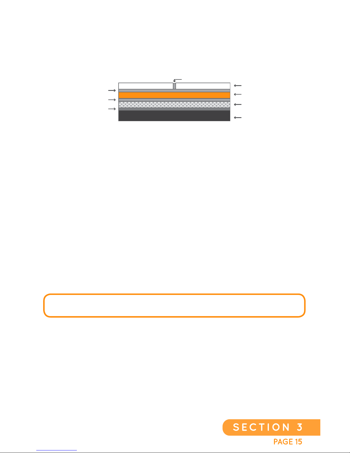
1. Install the crack suppressant/uncoupling mat per the manufacturer’s
guidelines.
2. Prepare the Heating Film according to the steps in the General
Installation Instructions beginning on page #24.
3.
Apply Heating Film to the crack suppressant/uncoupling mat using an
un-modified thin set that meets ANSI A118.1. While rolling back ½
sheet at a time, use a notch trowel to apply thin-set to the crack
suppressant/ uncoupling mat set the Heating Film onto the thin-set and,
using a roller, apply a continuous, even pressure with overlapping
strokes.
4. Install the tile on top of the Heating Film using an unmodified thin-set
mortar meeting the requirements of ANSI A118.1 to install ceramic and
stone tile. (See notes)
TILE INSTALLATION
CRACK SUPPRESSANT / UNCOUPLING MAT
OR WATERPROOF MEMBRANE INSTALLATION
CRACK SUPPRESANT / UNCOUPLING MAT INSTALLATION
GROUT
THIN-SET 3/8”
THIN-SET
THIN-SET
TILE / SLATE / STONE
UNCOUPLING MAT
HEATING FILM
SLAB
GROUT
FLOOR SENSOR (INCLUDED WITH ALL THERMOSTATS)
M
UST BE PROPERLY INSTALLED.
Page 16
PAGE 161
SECTION 3
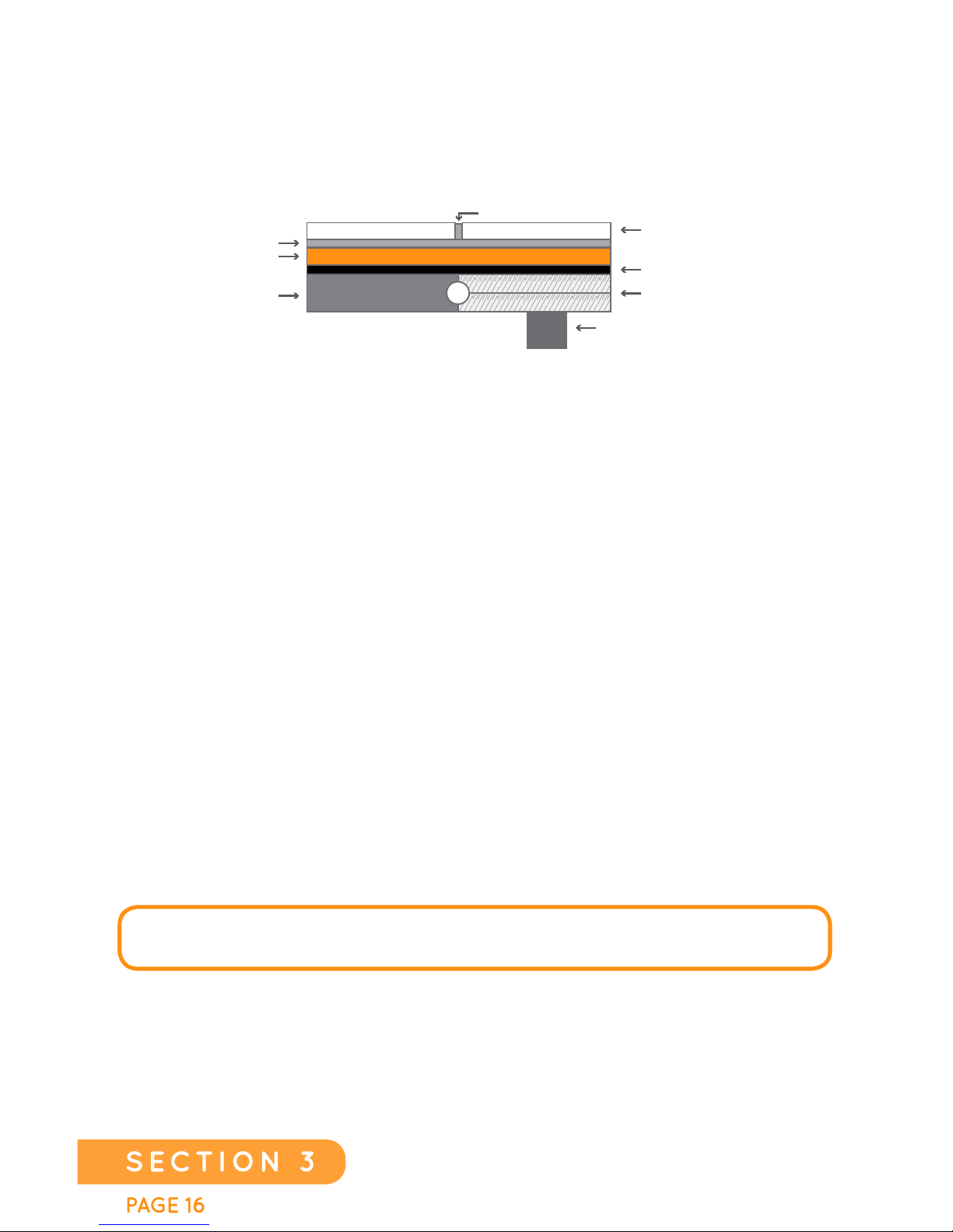
1. Prepare the Heating Film according to the steps in the General
Installation Instructions beginning on page #24.
2. Adhere the Heating Film to the slab or sub-floor using a moisture
resistant or water proofing indoor/outdoor flooring adhesive by
rolling
back 1/2 a sheet at a time, using a 3/16”-1/4” (5-6mm) V-notch trowel to
apply adhesive to the floor, setting the Heating Film down onto
3. the adhesive. Using a roller, apply a continuous, even pressure with
overlapping strokes making a permanent bond between the sub-floor
and film.
4. Follow the manufacturer’s recommended drying time for the membrane
you use before starting the tile installation.
5. Install the tile on top of the Heating Film using an unmodified thin-set
mortar meeting the requirements of ANSI A118.1 to install ceramic and
stone tile. (See notes)
TILE INSTALLATION
(WET AREA)
SLAB OR PLYWOOD SUBFLOOR
GROUT
THIN-SET 3/8”
SLAB
HEATING FILM
JOIST 16” O.C. TYP.
TILE / SLATE / STONE
MOISTURE RESISTANT
ADHESIVE
PLYWOOD SUBFLOOR
OR
FLOOR SENSOR (INCLUDED WITH ALL THERMOSTATS)
MUST BE PROPERLY INSTALLED.
EverWarm Radiant Floors
Page 17
EverWarm Radiant Floors
PAGE 17
SECTION 3
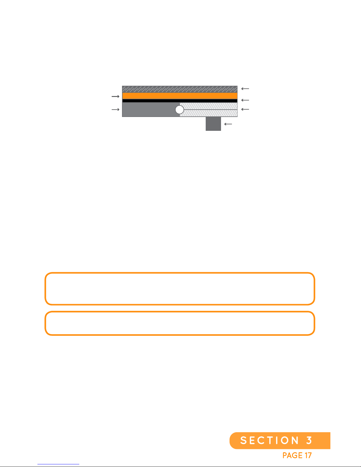
1. Start by laying out the underlayment that is recommended by the
laminate flooring manufacturer. When joining two sheets of
underlayment together, follow the manufacturer’s directions. So
me
manufacturers will have you overlap the underlayment and some will
have you “butt” each row against the previous one.
2. Prepare the Heating Film according to the steps in the General
Installation Instructions beginning on page #24.
3. Install the Laminate flooring per manufacturer’s installation guide.
LAMINATE INSTALLATION
FLOATING FLOOR
(WOOD/CORK/LAMINATE)
SLAB
FLOATING FLOOR
UNDERLAYMENT
HEATING FILM
JOIST 16” O.C. TYP.
PLYWOOD SUBFLOOR
OR
NOTE: CHECK WITH YOUR FLOORING MANUFACTURER FOR MAXIMUM
TEMPERATURE RATINGS THAT ARE APPROPRIATE FOR YOUR FLOORING AND
SET YOUR THERMOSTAT ACCORDINGLY.
FLOOR SENSOR (INCLUDED WITH ALL THERMOSTATS)
MUST BE PROPERLY INSTALLED.
Page 18
PAGE 181
SECTION 3
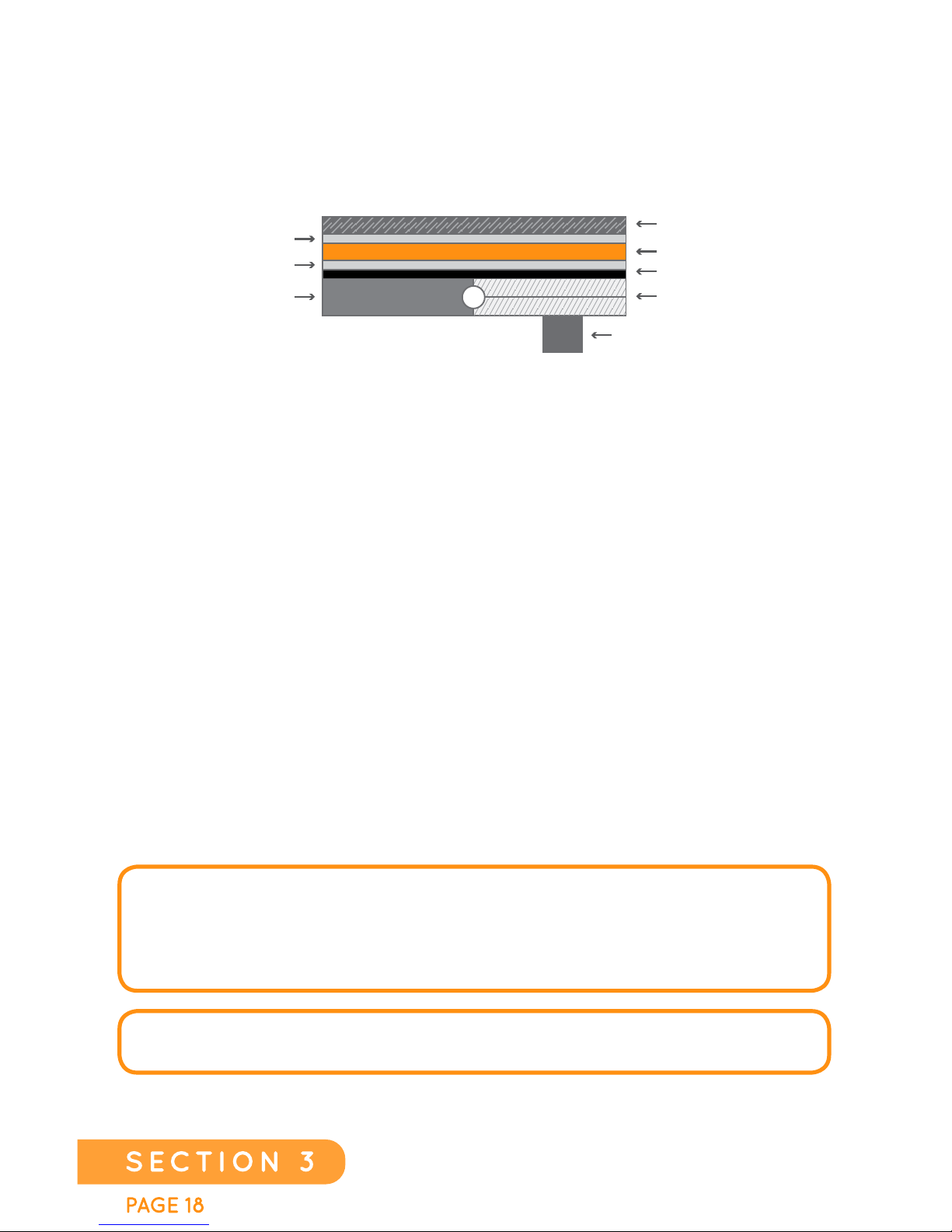
1. Prepare the Heating Film according to the steps in the General
Installation Instructions beginning on page #24.
2. Adhere the Heating Film to the slab or sub-floor using a moistu
re
resistant or water proofing indoor/outdoor flooring adhesive by rolling
back 1/2 a sheet at a time, using a 3/16”-1/4” (5-6mm) V-notch trowel to
apply adhesive to the floor, setting the Heating Film down onto
the adhesive. Using a roller, apply a continuous, even pressure with
overlapping strokes making a permanent bond between the sub-floor
and film.
3. To help acclimate the wood flooring to its new home, lay out the wood
floor according to the manufacturer’s recommendations. This will help
mitigate the effects of subsequent expansion and contraction. The wood
floor manufacturer and installer will help with directions for this process.
4. Install the wood flooring following the manufacturer’s guide.
WOOD FLOOR INSTALLATION
SLAB
WOOD FLOORING
HEATING FILM
GLUE/ADHESIVE
JOIST 16” O.C. TYP.
PLYWOOD SUBFLOOR
THERMAL BARRIER (OPTIONAL)
GLUE/ADHESIVE
OR
NOTE: NAILS MAY ONLY BE DRIVEN THROUGH THE WHITE
(NAIL STRIP) SECTIONS OF THE HEATING FILM. CHECK WITH YOUR
FLOORING MANUFACTURER FOR MAXIMUM TEMPERATURE RATINGS
THAT ARE APPROPRIATE FOR YOUR FLOORING AND SET YOUR
THERMOSTAT ACCORDINGLY.
FLOOR SENSOR (INCLUDED WITH ALL THERMOSTATS)
MUST BE PROPERLY INSTALLED.
EverWarm Radiant Floors
Page 19
EverWarm Radiant Floors
PAGE 19
SECTION 3
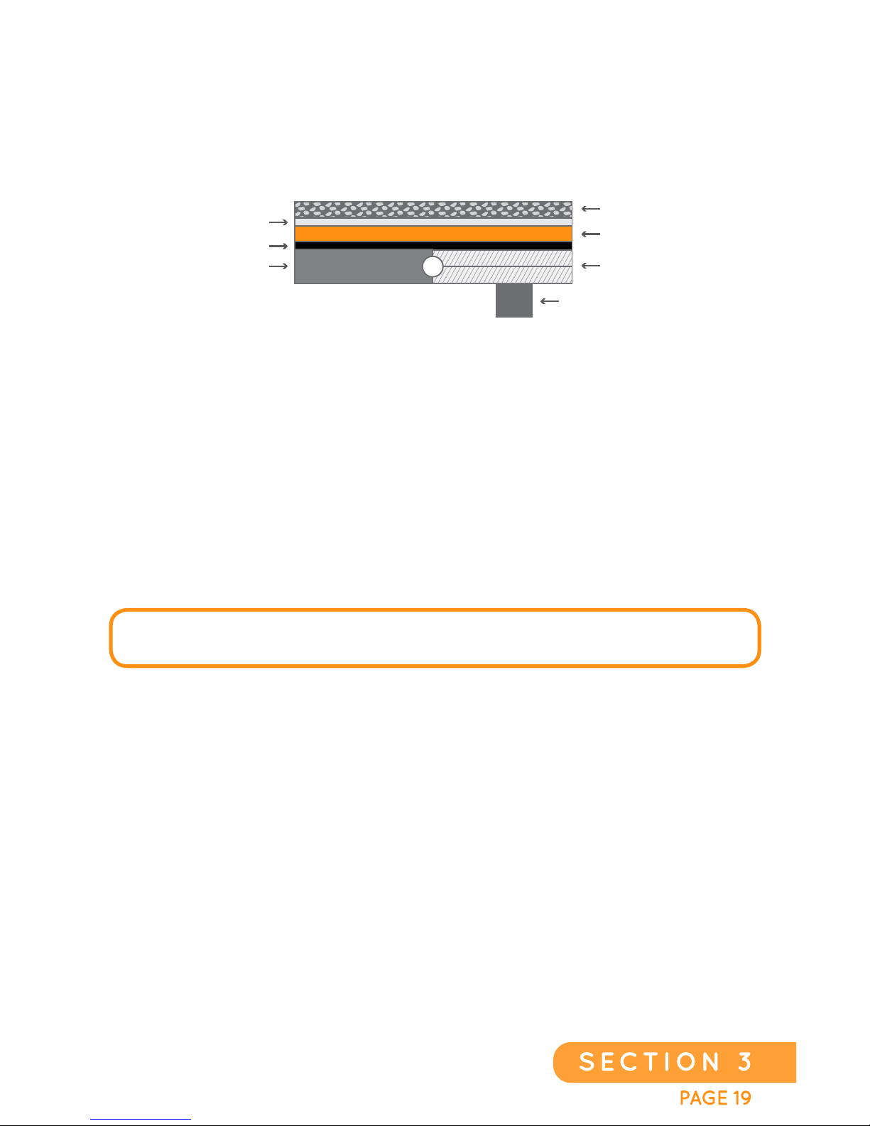
1. Prepare the Heating Film according to the process outlined in
the General Installation Instructions beginning on page #24.
2.
Install low R-Value carpet pad designed for radiant floor heating
systems according to the manufacturer’s instructions.
3. Install the carpet according to the manufacturer’s instructions.
Be sure carpet is approved for installation over radiant floor heat
products.
CARPET INSTALLATION
SLAB
CARPET PADDING
CARPET
HEATING FILM
JOIST 16” O.C. TYP.
PLYWOOD SUBFLOOR
THERMAL BARRIER (OPTIONAL)
OR
FL
O
OR SENSOR (INCLUDED WITH ALL THERMOSTATS)
MUST BE PROPERLY INSTALLED.
Page 20
PAGE 201
SECTION 3
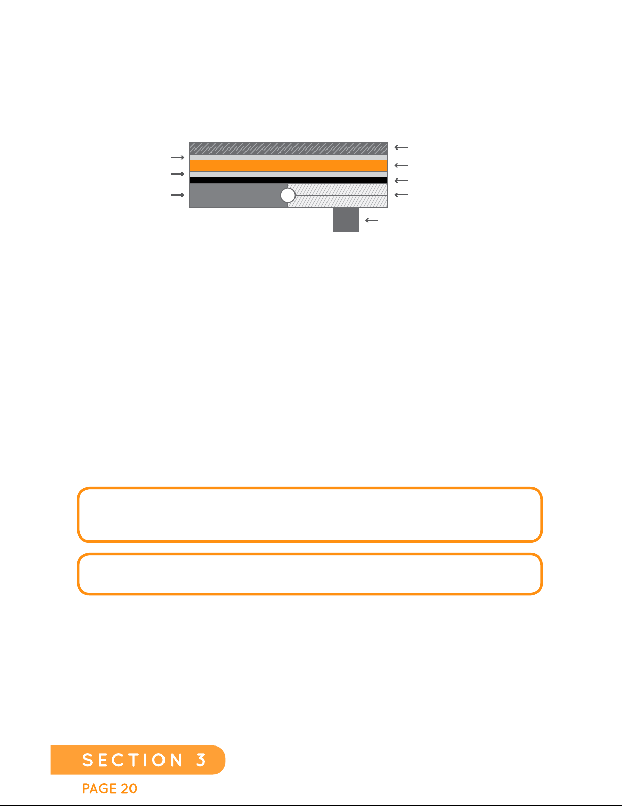
1. Prepare the Heating Film according to the process outlined in the
General Installation Instructions beginning on page #24.
2. Adhere t
he Heating Film to the slab or sub-floor using a moisture
resistant or water proofing indoor/outdoor flooring adhesive by rolling
back 1/2 a sheet at a time, using a 3/16”-1/4”(5-6mm) V-notch trowel
to apply adhesive to the floor, setting the Heating Film down onto the
adhesive. Using a roller, apply a continuous, even pressure with
overlapping strokes making a permanent bond between the sub-floor
and film.
3. Install the linoleum or vinyl flooring according to the manufacturer’s
specifications.
LINOLEUM AND VINYL INSTALLATION
SLAB
GLUE/ADHESIVE
FLOORING
THERMAL BARRIER (OPTIONAL)
HEATING FILM
JOIST 16” O.C. TYP.
PLYWOOD SUBFLOOR
GLUE/ADHESIVE
OR
NOTE: CHECK WITH THE FLOORING MANUFACTURER FOR MAXIMUM
TEMPERATURE RATINGS THAT ARE APPROPRIATE FOR YOUR FLOORING AND
S
ET THE THERMOSTAT ACCORDINGLY.
FLOOR SENSOR (INCLUDED WITH ALL THERMOSTATS)
MUST BE PROPERLY INSTALLED.
EverWarm Radiant Floors
Page 21
EverWarm Radiant Floors
PAGE 21
SECTION 4
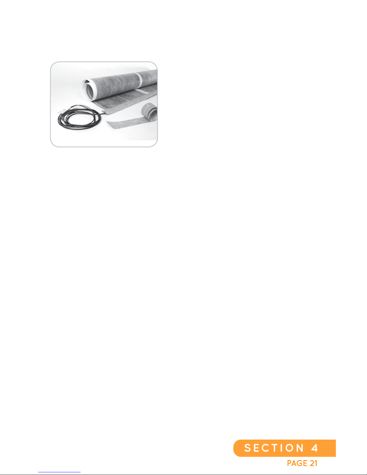
The per-assembled radiant heat flooring
system is designed with ease of installation
in mind. These kits feature a per-attached
Harness, sealed with our Edge Sealing
Tape. This Kit also features a second,
narrower piece of Edge Sealing Tape for
sealing any edges or holes that are
intentionally cut during the installation.
1. Carefully plan the layout of the Heating Film for the installation.
2. Cut the Heating Film to the required length and dimension.
3. Seal the end that has been cut, by applying the narrow (2.4” inches wide)
Edge Sealing Tape.
4. There are two (2) wires that protrude approximately one (1) inch from the
end of the pre-assembled, attached, and pre-taped wire Harness
. These are
used for adding another sheet of Heating Film. If you are adding a second
sheet to your system please refer to Harness, Adders, and Jumpers located
in the General Installation Instructions beginning on page #24. If you are not
adding a second sheet then proceed to the next step.
5. Check the OHMs reading (see pg #28 in this Guide).
6. A floor sensor MUST be installed and is included with the thermostat
(See pg #31 in this Guide).
7. After completing these steps please turn to the following sections for each
specific floor application:
Page #13-16
Page #17
Page #18
Page #19
Ceramic Tile, Stone, or Slate
Laminat We ood
Nail Down Wood
Carpet
Vinyl or Linoleum
Page #20
8. Install the thermostat according to the manufacturer’s instructions.
INSTALLING EVERWARM KITS
CHK-15-120, CHK-25-120
(
Kit description: TYPE - SQUARE FOOTAGE- VOLTAGE, Example: EverWarm Kit-15 square feet-120 volt system.)
Page 22
PAGE 221
SECTION 4
1.Carefully plan the layout of the Heating Film for the installation.
2. Cut the Heating Film to length.
3. Seal both edges of the Heating Film that were cut with the narrower supplied
size of the Edge Sealing Tape (part #EST-2.4-42).
4. There are two (2) wires that protrude approximately one (1) inch from the
end of the per-assembled factory-attached, and Edge Seal Taped wire
Harness and Adder. These are used for adding the second sheet of Heating
Film that was
trimmed off of the 50 Sq-ft Kit. If you are adding a second sheet
to your system please refer to Harness, Adders, and Jumpers located in the
General Installation Instructions on page #27. If you are not adding a second
sheet then proceed to the next step.
5. Check the OHMs reading (see pg #28 in this Guide).
6. A floor sensor MUST be installed and is included with the thermostat (See
pg #31 in this Guide).
7. After completing these steps please turn to the following pages for each
specific floor application:
Page #13-16
Page #17
Page #18
Page #19
Ceramic Tile, Stone, or Slate
Laminate
Wood
Carpet
Vinyl or Linoleum
Page #20
8. Install the thermostat according to the manufacturer’s instructions.
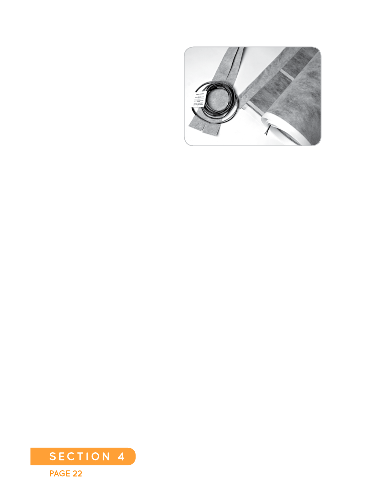
The per-assembled radiant heat
flooring system is designed with
ease of installation
in mind. These
kits feature an installation system
that includes an attached Harness
and Adder, completely sealed with
our Edge Sealing Tape. This Kit
also features two, narrower pieces
of Edge Sealing Tape for sealing
the custom installation.
CHK-50-120, CHK-50-240
(Kit description: TYPE - SQUARE FOOTAGE- VOLTAGE, Example: EverWarm Kit-50 square feet-120 volt system.)
EverWarm Radiant Floors
Page 23
EverWarm Radiant Floors
PAGE 23
SECTION 4
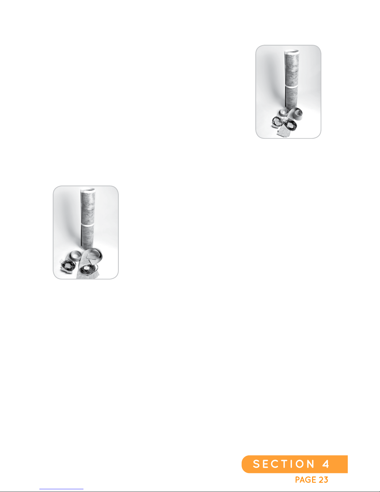
These kits are all supplied with the CarbonicHeat Film,
a J-2 Harness, an A-2 Adder, and eight (8) pieces of
Edge Sealing Tape. This will be enough material to
complete an 80-100 square foot room. A Crimping Tool
(part #CHP-01), scissors, tape measure, wire cutters/
strippers, and a Volt meter will be needed to complete
your job. Please follow the steps in the General
Installation Instructions on pages #24 thru #32.
These kits are all supplied with the CarbonicHeat Film,
two (2) J-4 Harnesses and sixteen (16) pieces of Edge
Sealing Tape. This is enough material to complete a
200 square foot room or two 100 square foot rooms.
Required for the job will be a Crimping Tool (part
#CHP-01), scissors, tape measure, wire cutters/
strippers, and a Volt meter. Please follow the steps in
the General Installation Guide on pages #24 thru #32.
CHK-100-120, CHK-100-240
(Kit description: TYPE - SQUARE FOOTAGE- VOLTAGE, Example: EverWarm Kit-120 square feet-120 volt system.)
CHK-200-240
(Kit description: TYPE - SQUARE FOOTAGE- VOLTAGE, Example: EverWarm Kit-200 square feet-240 volt system.)
Page 24
PAGE 241
SECTION 5SECTION 5
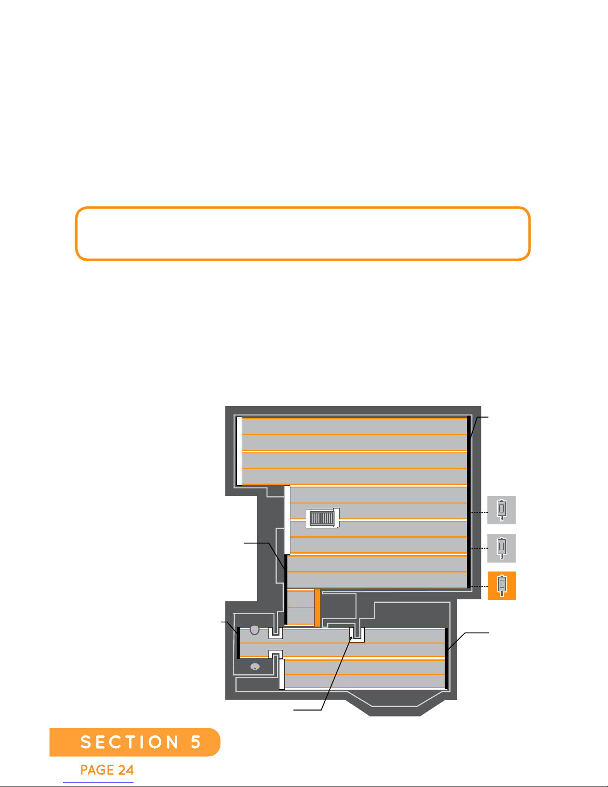
THERMOSTAT
SLAVE 1
SLAVE 2
JUMPER
A-240
ADDER
A-240
ADDER
J-240
HARNESS
J3-240
HARNESS
EXAMPLE OF A
400 SQ-FT SYSTEM.
Qty 1 Master thermostat
Qty 2 Slave units
Qty 1 JP-60 (60” Jumper)
Qty 2 A-240 Adder
Qty 1 J-240 Harness
Qty 1 J3-240 Harness
GENERAL INSTALLATION
INSTRUCTIONS
LAYOUT
The installation of EverWarm Film begins with planning a layout for the
Heating Film. This helps the installer understand how much Heating Film will
be needed, and which (and how many) Wiring Harnesses, Jumpers, Adders,
and extra Edge Sealing Tape might be needed. Additionally, a pre-planned
layout will determine thermostat (and possibly slave thermostat) locations.
FIRST, DETERMINE THE NUMBER OF S QUARE FEET OF HEATING FILM THAT
ARE REQUIRED FOR THE INSTALLATION. THIS WILL HELP TO DETERMINE
THE VOLTAGE NEEDED FOR THE INSTALLATION.
The Heating Film is capable of running on 120 volts or 240 volts. Installations
using 120 volts are limited to 100 square feet of Heating Film per dedicated
15 amp circuit. Installations using 240 volts are capable of a maximum 200
square feet of Heating Film per a dedicated 15 amp circuit. Each circuit can
be controlled individually by using a standard individual thermostat for
complete zone control, or up to ten circuits (maximum 2000 sq-ft) may be
controlled from one master thermostat.
EverWarm Radiant Floors
Page 25
EverWarm Radiant Floors
PAGE 25
SECTION 5SECTION 5
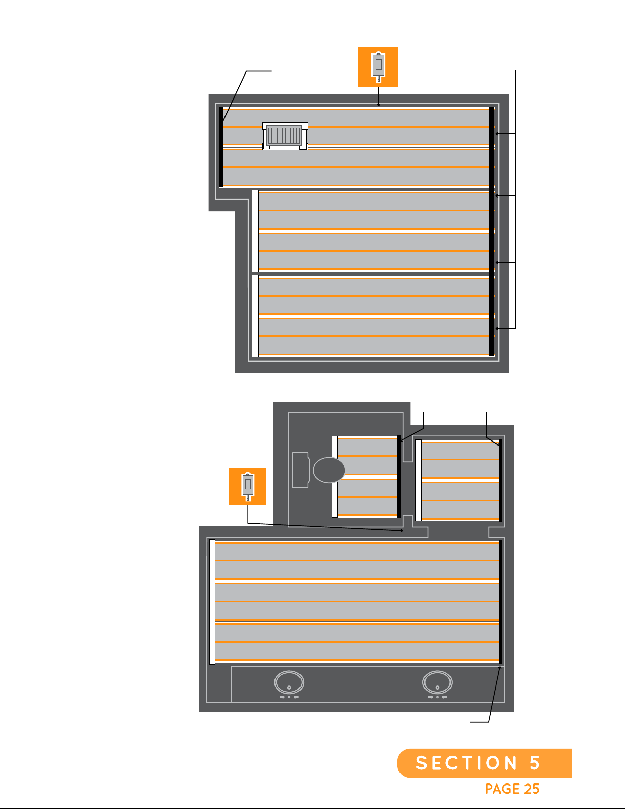
THERMOSTAT
J-120
HARNESS
J-120
HARNESS
J2-120
HARNESS
J3-240
HARNESS
THERMOSTAT
A-240
ADDER
EXAMPLE OF A
200 SQ-FT SYSTEM.
Qty 1 Thermostat
Qty 1 A-240 Adder
Qty 1 J3-240 Harness
EXAMPLE OF A
100 SQ-FT SYSTEM.
Qty 1 Thermostat
Qty 2 J-120 Harness
Qty 1 J2-120 Harness
Page 26
PAGE 261
SECTION 5
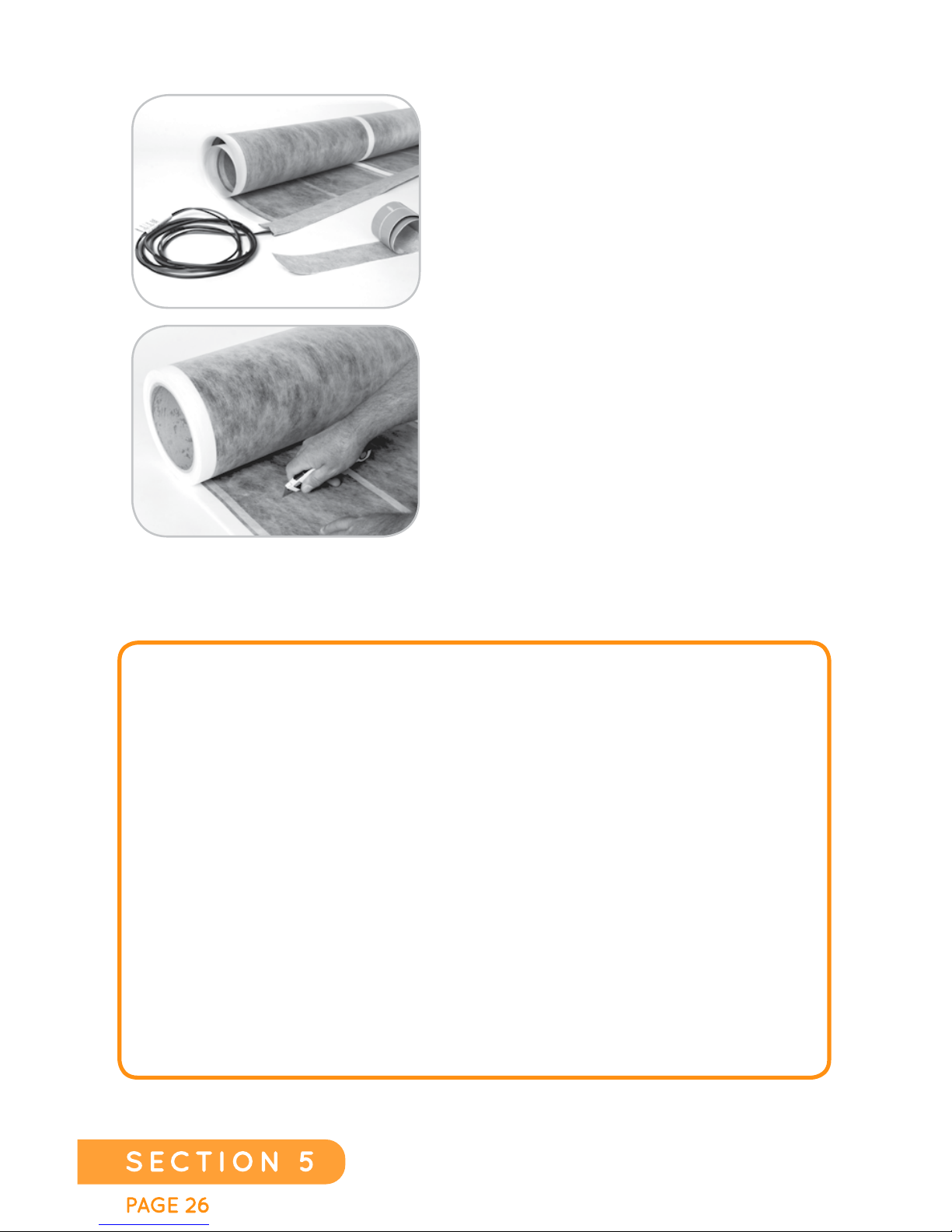
INSTALLING THE HEATING FILM
1. Carefully plan the layout of the Heating
Film for the installation.
2. Cut the Heating Film to length required.
3. Cut any holes or notches according to
the installation plan (toilet flanges,
electrical outlets, floor registers, doors,
etc.). Sheets of Heating Film may be
laid out, side-by-side and then wired
together. White, non-heating areas
(nailing strips) are allowed to be
trimmed off the material as needed. The
Heating Film can be installed with some
space between sheets, if deemed
necessary; however, it should be noted
that “cold spots” will form if the gap is
too great for the thermal heat expansion
to overlap. The thermal expansion for
this product is up to three (3) inches from the edge of the active
heating area.
1. UNDER NO CIRCUMSTANCES SHOULD THE ACTIVE AREAS (GRAY) OF
THE HEATING FILM BE ALLOWED TO OVERLAP ITSELF OR ONTO
ADJACENT PIECES OF HEATING FILM.
2. ANY TRIMMING OF THE HEATING FILM THAT INCLUDES GRAY (ACTIVE
HEATING) AREAS MUST BE TAPED WITH THE EDGE SEALING TAPE.
3. THE HEATING FILM MAY NOT BE INSTALLED WITHIN TEN (10) INCHES OF
ANY DRAIN, INCLUDING TOILET FLANGES.
4. NATIONAL ELECTRIC CODE FORBIDS THE PLACEMENT OF NAILS,
STAPLES, OR OTHER FASTENERS THROUGH THE CARBON “GRAY”
HEATING AREA OR COPPER BUS BAR ZONES.
5. IF A NAIL OR STAPLE IS ACCIDENTALLY PLACED THROUGH ANY OF
THESE AREAS, THE PENETRATION MUST BE REMOVED, AND THE HOLE
NEEDS TO BE TAPED ON BOTH SIDES WITH THE EDGE SEALING TAPE.
EverWarm Radiant Floors
Page 27
EverWarm Radiant Floors
PAGE 27
SECTION 5
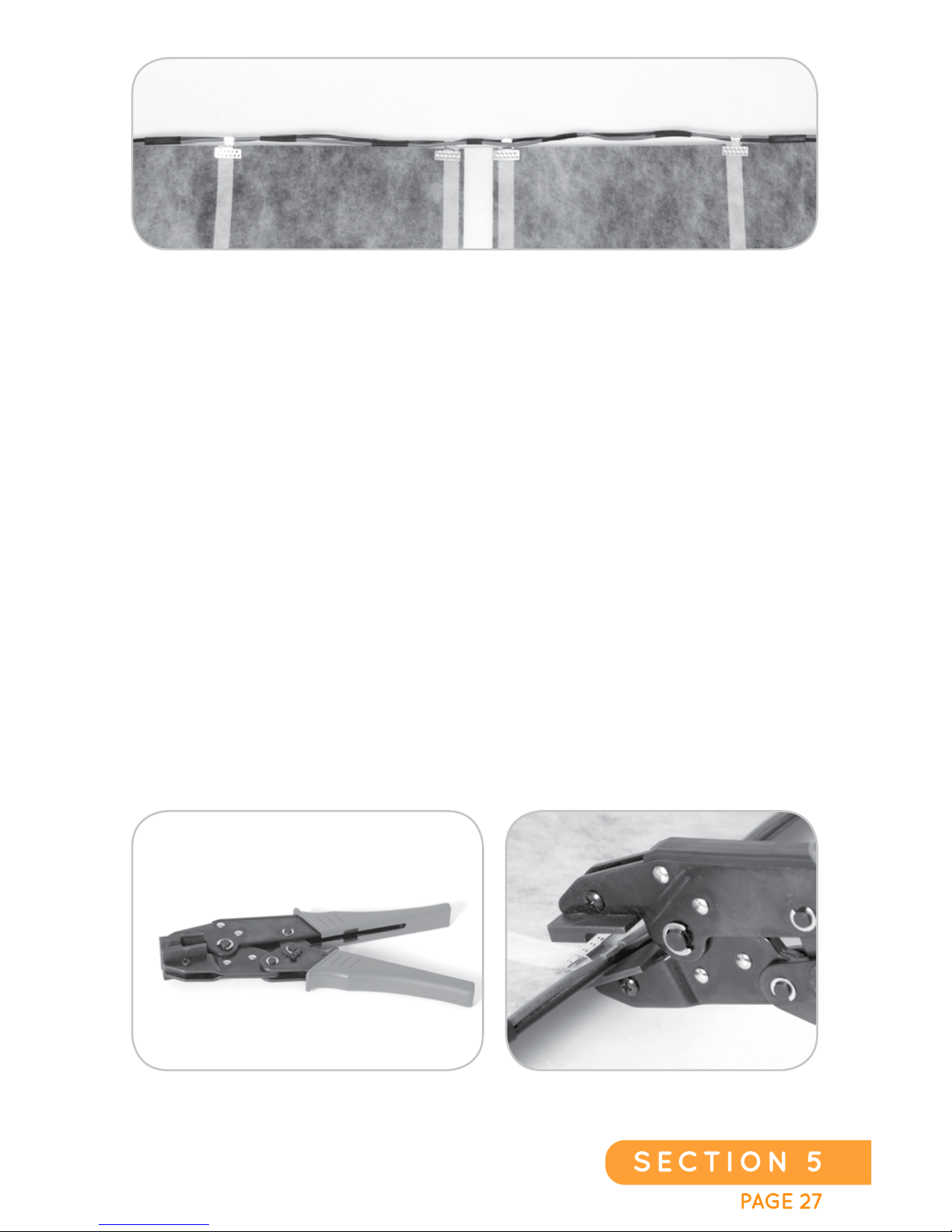
HARNESS, ADDERS, AND JUMPERS
A Crimping Tool (CHP-01) must be used to attach Harnesses, Adders, and
Jumpers to the Heating Film.
First attach the center Terminal Crimps on the Harness so the spacing will
stay “true” to the center of the Heating Film. This is extremely important
when setting up to use a Multi-sheet Harness or a Multi-sheet Adder.
Failure to do so will result in misalignment of the sheets and the installation
won’t be able to continue until the spacing issue is corrected. It is important
to note that there are six (6) Terminal Crimps per sheet for 120 volt and
four (4) Terminal Crimps per sheet for 240 volt system.
The crimping terminals have 11 lance “bayonets” that are designed to
pierce the outer insulation layer of the Heating Film and make connection
with the copper bus bars. The Crimping Terminal is wider than the copper
bus bar so it is not necessary for all the bayonets to pierce the copper
bars, but care should be taken to have as many of the bayonets pierce the
copper bus bars as possible. When finished, the Crimping Terminal must
lay flat against the Heating Film and the bayonets must protrude through
to the female side of the Crimping Terminal to be properly crimped.
Page 28

PAGE 281
SECTION 5
FOR 120 VOLT INSTALLATIONS, USE THIS FORMULA:
Example: A typical 10’ X 10’ (100 sq-ft) room will have approximately
three sheets, for a total of 30 linear feet of Heating Film. Divide 218 by
30, yielding a calculated ohms reading of 7.27.
FOR 240 VOLT INSTALLATIONS, USE THIS FORMULA:
Example: A typical 10’ X 10’ (100 sq-ft) room will have approximately three
sheets, for a total of 30 linear feet of Heating Film. Divide 872 by 30,
yielding a calculated ohms reading of 29.07.
1 linear foot of Heating Film = 3.38 square feet of Heating Film. The linear
foot calculation uses the full width (40.6 inches) of EverWarm Film. If a
sheet is cut in half (20.30 inches), along the center white strip cut line, then
the “linear feet” is half the length.
R =
218
___
L
R =
872
___
L
TESTING THE CONNECTION AND HEATING FILM;
MEASURING OHMS
Measure the ohms (resistance) by connecting the red and black wires from
the “cold lead” using a volt meter. Compare this measured value to the
“calculated” OHMs in Step #2. This measurement should be done with film
at room temperature as temperature affects the resistance reading.
The integrity of the installation can be tested simply by measuring the
resistance of the red and black cold lead wires prior to running the cold leads
up through the conduit to the wall junction box. The following simple formula
will provide you the CALCULATED RESISTANCE for the Heating Film
installation. These calculations are based upon an average installed product
temperature. These values will fluctuate +/- 20% based upon the ambient
temperature in the environment in which the product is operating.
NOTE: TO AVOID ELECTRICAL SHOCK, YOU MUST NOT CONNECT THE
THERMOSTAT AND/OR A SLAVE UNIT TO THE COLD LEADS UNTIL THE
TAPING PROCEDURE HAS BEEN COMPLETED (SEE NEXT STEP).
The following formulas are voltage specific and are based on the linear length
of the installed film. The value “R” represents the calculated resistance
(ohms). The value “L” represents the Total linear length of Heating Film.
EverWarm Radiant Floors
Page 29
EverWarm Radiant Floors
PAGE 29
SECTION 5
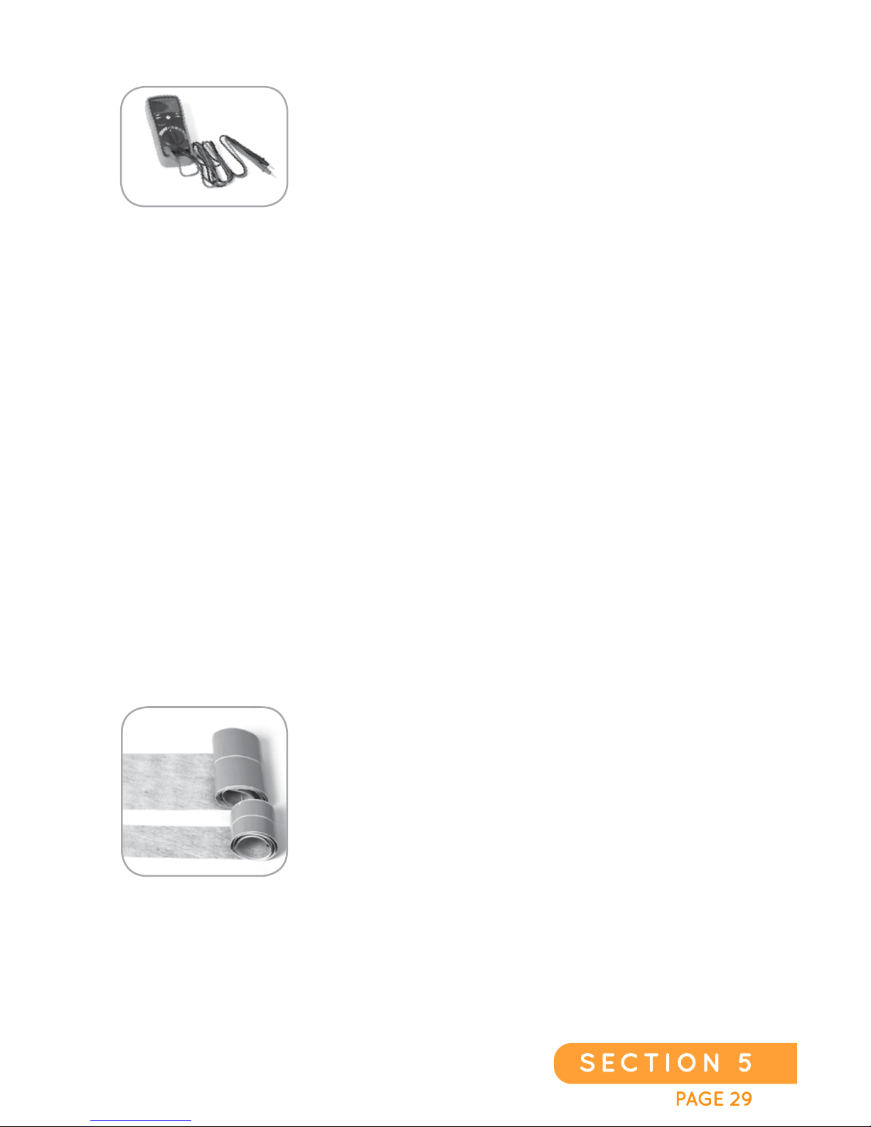
OHM’S TESTING
A DIGITAL multi-meter is required to perform the
resistance test. Analog meters (which have a needle
rather than digital readout) are not recommended,
as they do not provide accurate enough reading
when calculating the formulas. Be sure the film is at
room temperature or incorrect readings will result.
1. Calculate Resistance (ohms) as shown on the previous page #28.
2. Set the meter for the reading resistance in ohms – the symbol is Ω.
3. Touch the meter’s probes to the red and black cold lead wires from the
Harness.
4. Read the resistance from the digital display.
5. Compare “calculated resistance” to “real time resistance”
If any Terminal Crimp connection was missed, the result will be that the
resistance measurement will be significantly HIGHER than the calculated
resistance. If the MEASURED resistance exceeds 20% of the calculated
resistance, then the connections should be checked for proper contact
of the Crimping Terminals to the copper bus bars. Resistance should be
recorded and a second resistance test should be performed after the
flooring installation to verify that no damage has occurred to the Heating
Film or Harness during the installation.
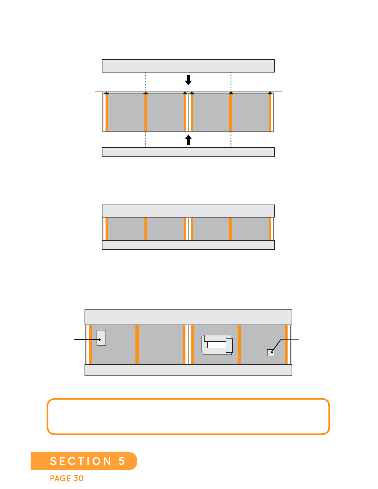
APPLYING THE EDGE SEALING TAPE
Use the Edge Sealing Tape (provided in Kits) to seal
both ends of the Heating Film. The Edge Sealing
Tape comes in two different widths (4.8” wide and
2.4” wide). The 4.8” wide tape is designed to seal
the edge of the sheet to which the Harness or Adder
is attached. The 2.4” wide tape is to seal the edge
of the sheet that does not have a Harness or Adder
attached, or any section of the Heating Film that has
been cut as part of the installation process. Simply
attach one edge of the Tape on one side of the sheet and fold over the other
half, thereby s
ealing each end of the Heating Film. You may need to
purchase additional Edge Sealing Tape (part #EST-4.8-42) to enable you to
completely tape over and cover/seal any holes that have been cut into the
Heating Film (for angles, sockets, islands, etc.).
Page 30
PAGE 301
SECTION 5
TAPE
FINISH
APPLICATIONS
STEP 1
STEP 2
TAPE MUST BE APPLIED TO BOTH SIDES OF THE FILM DURING TAPING
TAPE MUST BE APPLIED TO BOTH SIDES OF THE FILM DURING TAPING
FOR PATCHING HOLES, SLITS, CUTS, SCRAPES
AND ANY EXPOSED GRAY AREA EDGES
TAPE MUST BE APPLIED TO BOTH SIDES OF THE FILM DURING TAPING
SLIT/CUT
PATCH
NAIL HOLE
PATCH
HOLE
NOTE: FAILURE TO PERFORM THIS STEP WILL RESULT IN CONDUCTION
OF ELECTRICITY FROM THE OPEN ENDS OF THE COPPER BUS BARS WHEN
EMBEDDED IN THINSET. DO NOT SUBSTITUTE TAPE.
EverWarm Radiant Floors
Page 31
EverWarm Radiant Floors
PAGE 31
SECTION 5
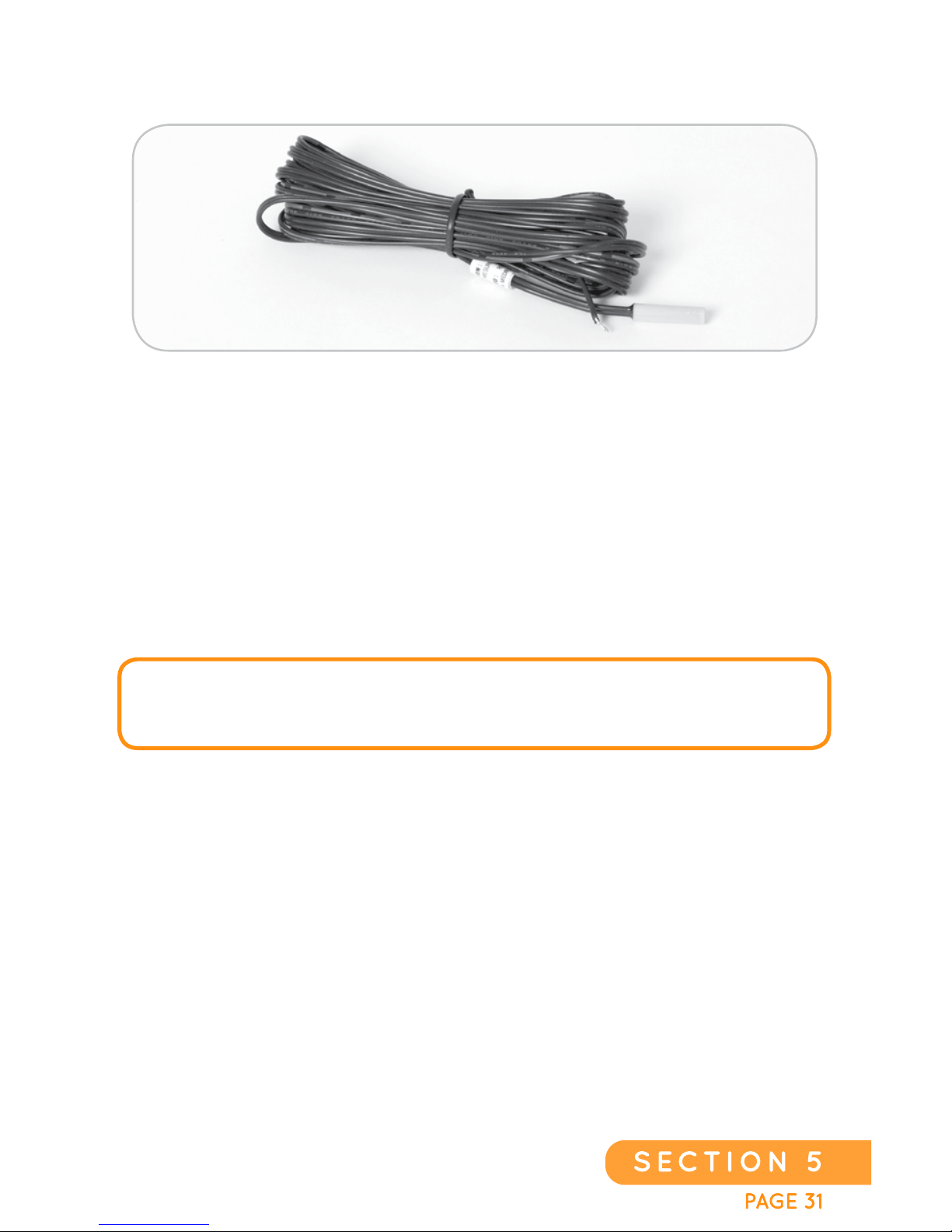
INSTALLING THE FLOOR SENSOR AND RUNNING THE
COLD LEADS UP WALL
Each thermostat includes a floor sensor. Install the sensor perpendicular to
the wall at least 12 inches from the wall and not near other sources of heat.
The sensor MUST be either mounted on one of the white, non- heat
producing strips or placed BETWEEN sheets of Heating Film. Do NOT
place floor sensor directly on the heating area. The sensor should be taped
to the sheet using a piece of Edge Sealing Tape. The sensor wire is to be
run to the conduit and up to the thermostat junction box. It is not uncommon
to route a channel across the non-heat generating areas within the sub-floor
so that the sensor is in a more level position to aid with the subsequent
installation of the floor covering.
NOTE: CHECK WITH YOUR F
LOORING MANUFACTURER FOR MAXIMUM
TEMPERATURE RATING THAT IS APPROPRIATE FOR YOUR FLOORING AND SET
YOUR THERMOSTAT ACCORDINGLY.
Page 32
PAGE 321
SECTION 5
ELECTRICAL REQUIREMENTS
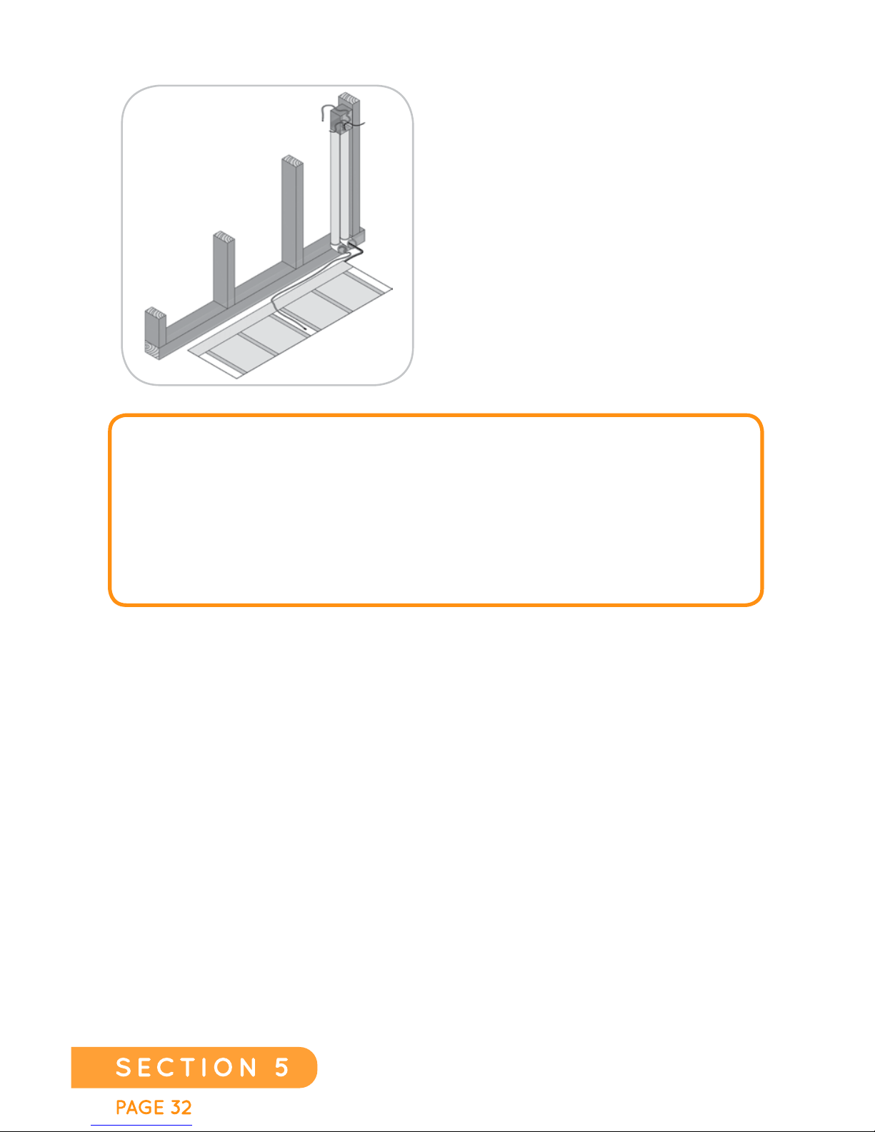
A single-gang junction box or a
double-gang box is required for the
thermostat and slave connections.
Two conduits should be placed from
the junction box to the bottom of
the rough-in wall. One conduit is for
the cold leads from the Heating Film
and the other conduit is for the floor
sensor. The floor sensor wire should
not be placed in the same conduit as
the supply leads.
NO
TE: TO REMAIN COMPLIANT WITH THE NATIONAL ELECTRICAL CODE
(NEC, ARTICLE 424 PART IX) THE ELECTRICAL INSTALLATION MUST USE A
TERMINAL JUNCTION TO BE CONSIDERED A HEATING SHEET SET. THIS IS A
REQUIRED PART OF THE INSTALLATION PROCEDURE. THE HEATING FILM
CAN ONLY BE INSTALLED ON A DEDICATED ELECTRICAL CIRCUIT(S), NOT TO
EXCEED 80% OF THE BREAKER’S RATED CAPACITY. POWER IS USED @ 15
WATTS PER SQUARE FOOT OF HEATING FILM, WITH A THERMAL OUTPUT OF
51 BRITISH THERMAL UNITS (BTU’S) PER SQUARE FOOT OF HEATING FILM.
ATTACHING THE THERMOSTAT
Before installation of the thermostat, always make sure the power is off.
The installation should be done by a qualified electrician in accordance
with all current electrical and building regulations. The installer needs
to follow the thermostat manufacturer’s instruction manual. Once the
thermostat has been installed, complete the set-up programming and
make sure to program the floor sensor temperature to the flooring
manufacturer’s desired temperature.
EverWarm Radiant Floors
Page 33
EverWarm Radiant Floors
PAGE 33
SECTION 6
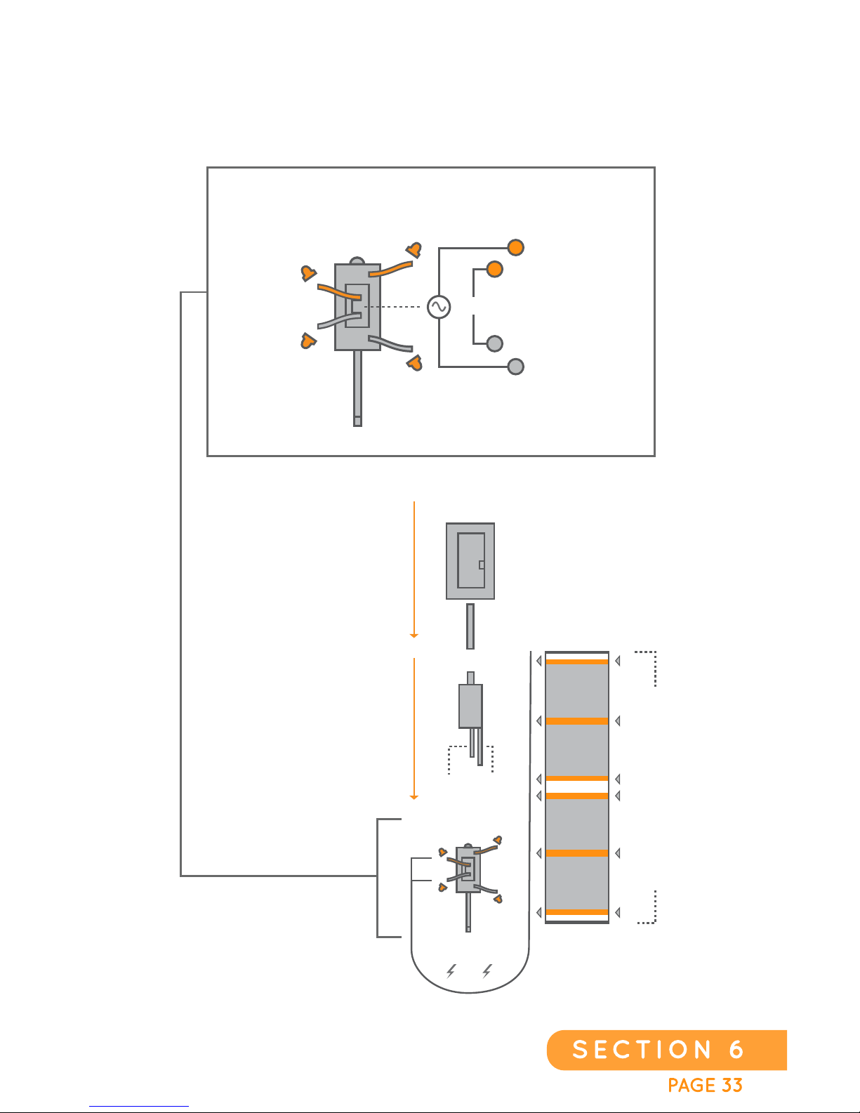
120 VOLT CONFIGURATION
SINGLE SHEET SET UP
FLOOR
HE AT
(LOAD)
FLOOR SENSOR
LOAD
POWER
SU P P LY
CONNECTION
THERMOSTAT
BREAKER BOX
WALL BOX
THERMOSTAT
FLOOR
HE AT
(LOAD)
FLOOR
HE AT
(LOAD)
FLOOR
SENSOR
120 VOLT LOCATIONS - 40.6”
144”
Page 34
PAGE 341
SECTION 6
FLOOR
HE AT
(LOAD)
FLOOR SENSOR
LOAD
POWER
SU P P LY
CONNECTION
THERMOSTAT
BREAKER BOX
WALL BOX
THERMOSTAT
FLOOR
HE AT
(LOAD)
FLOOR
HE AT
(LOAD)
FLOOR
SENSOR
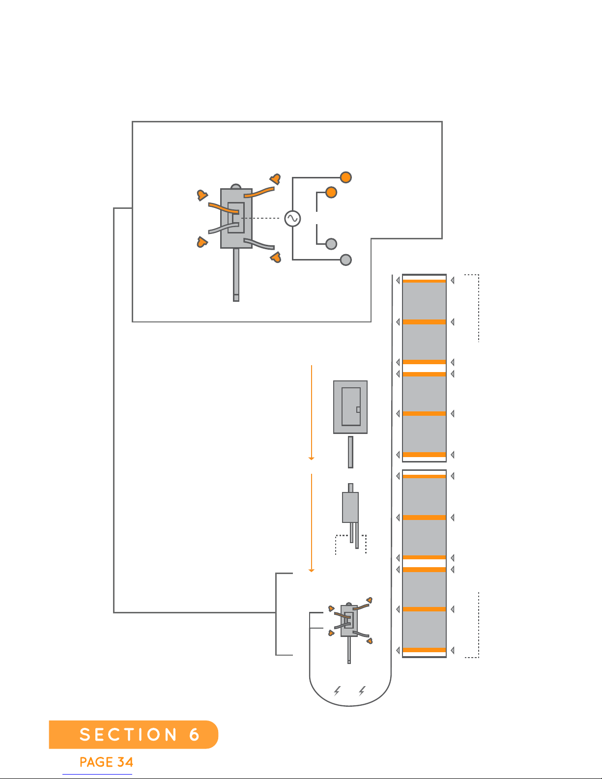
120 VOLT CONTACT LOCATIONS - TWO PANELS - 81.2”
144”
120 VOLT CONFIGURATION
MULTI SHEET SET UP
EverWarm Radiant Floors
Page 35
EverWarm Radiant Floors
PAGE 35
SECTION 7
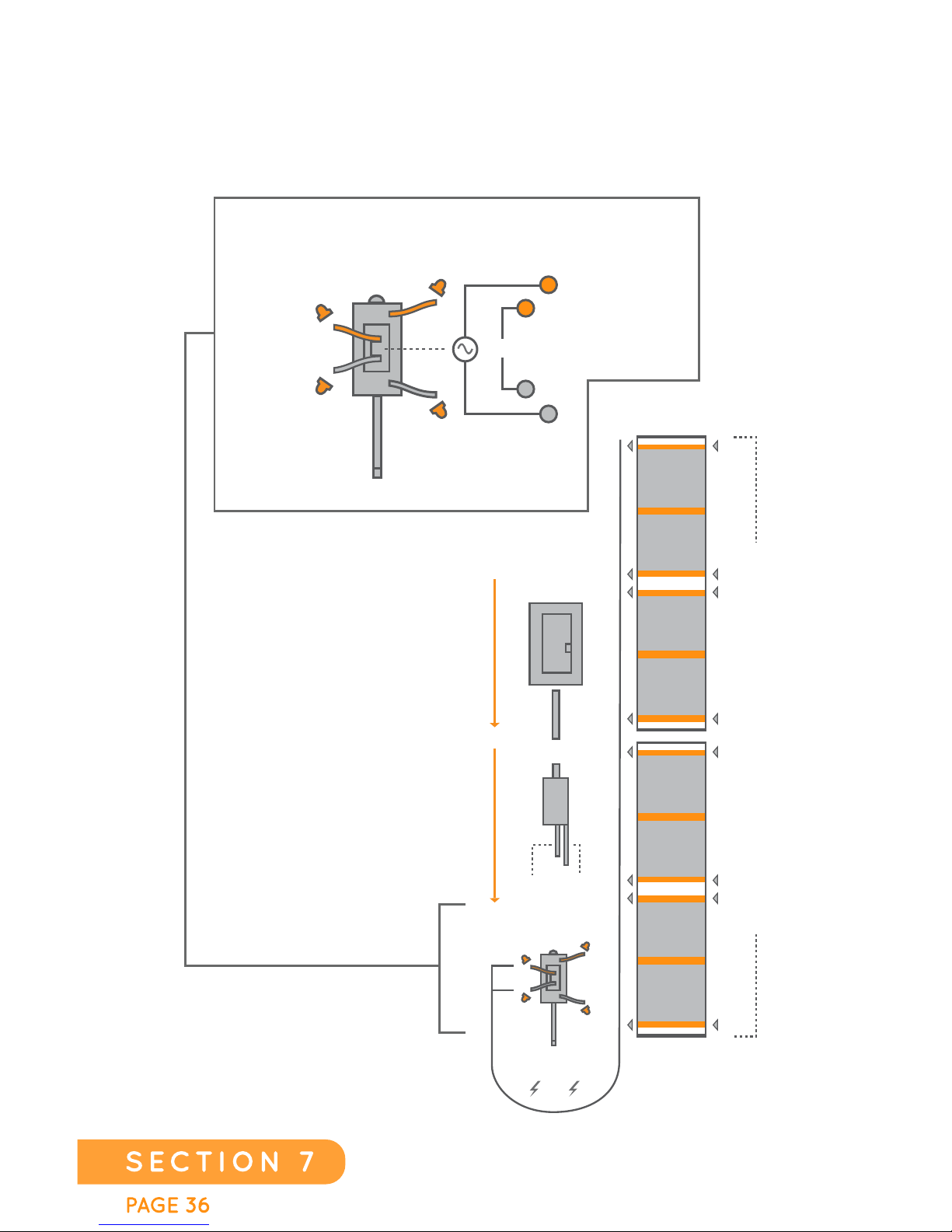
FLOOR
HE AT
(LOAD)
FLOOR SENSOR
LOAD
POWER
SU P P LY
CONNECTION
THERMOSTAT
BREAKER BOX
WALL BOX
THERMOSTAT
FLOOR
HE AT
(LOAD)
FLOOR
HE AT
(LOAD)
FLOOR
SENSOR
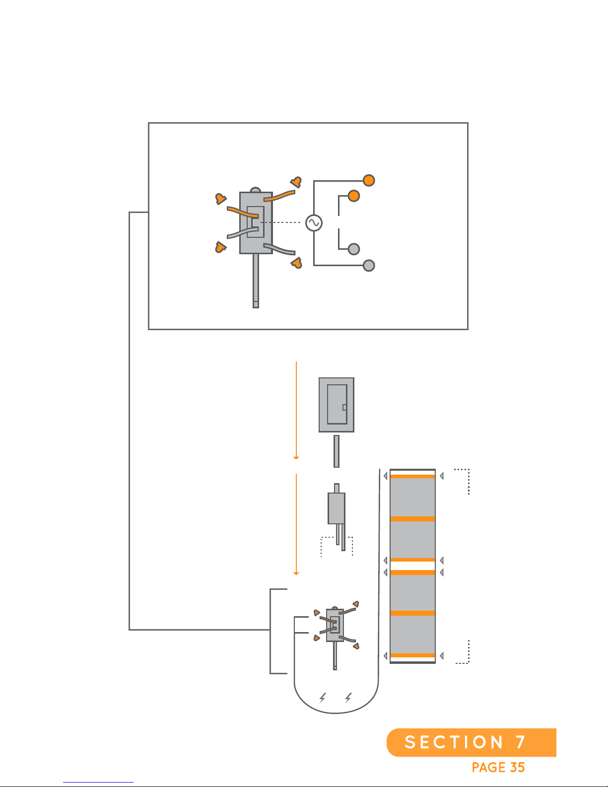
240 VOLT LOCATIONS - 40.6”
144”
240 VOLT
CONFIGURATION
SINGLE SHEET SET UP
Page 36
PAGE 361
SECTION 7
FLOOR
HE AT
(LOAD)
FLOOR SENSOR
LOAD
POWER
SU P P LY
CONNECTION
THERMOSTAT
BREAKER BOX
WALL BOX
THERMOSTAT
FLOOR
HE AT
(LOAD)
FLOOR
HE AT
(LOAD)
FLOOR
SENSOR
240 VOLT CONTACT LOCATIONS - TWO PANELS - 81.2”
144”
240 VOLT CONFIGURATION
MULTI SHEET SET UP
EverWarm Radiant Floors
Page 37
EverWarm Radiant Floors
PAGE 37
SECTION 8
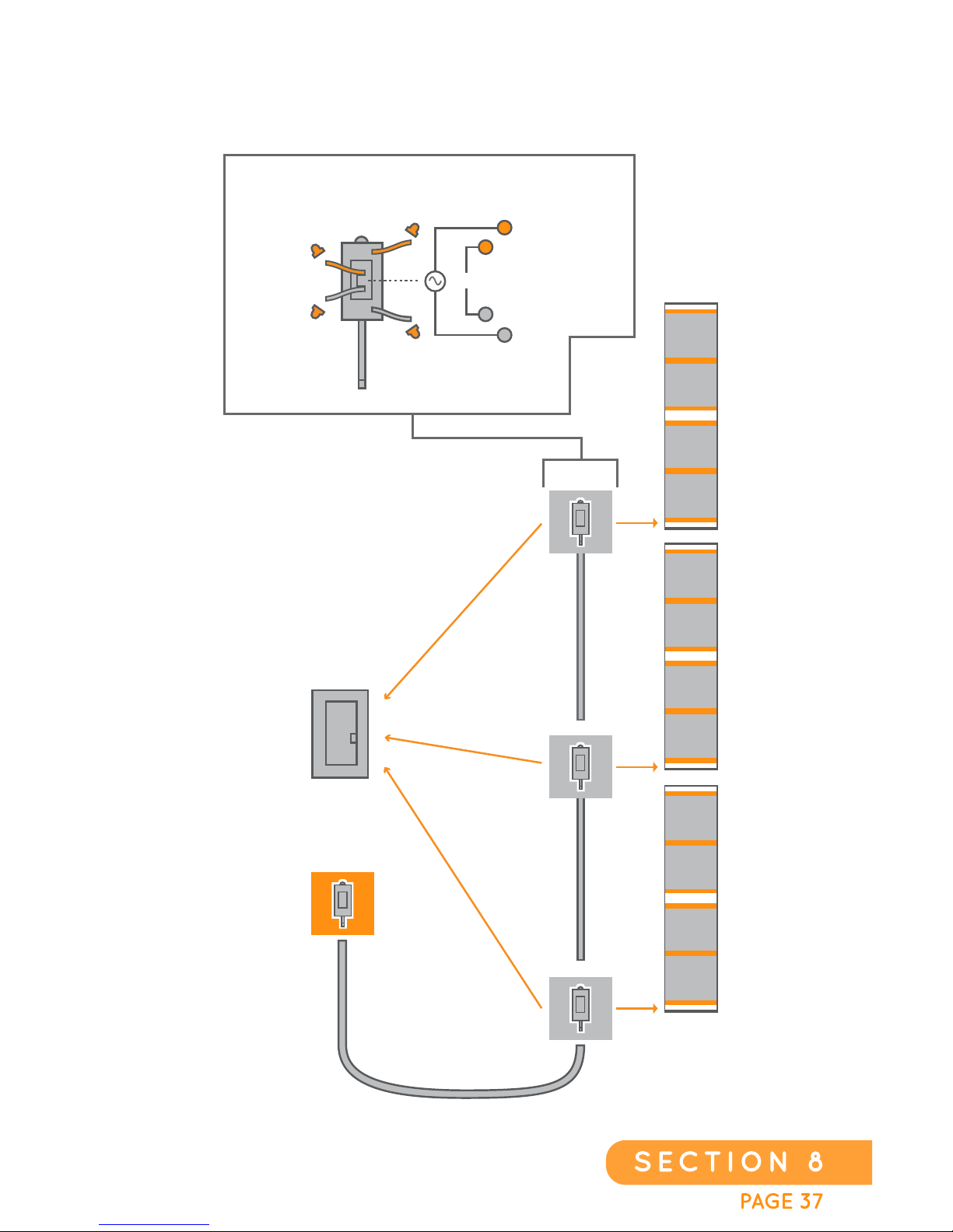
FLOOR
HE AT
(LOAD)
FLOOR SENSOR
LOAD
POWER
SUP P LY
CONNECTION
SLAVE UNIT
THERMOSTAT
ZONE 1
ZONE 2
ZONE 3
SLAVE 2
SLAVE 1
SLAVE 3
BREAKER BOX
DEDICATED CIRCUIT
DEDICATED CIRCUIT
DEDICATED CIRCUIT
MULTIPLE ZONES
Page 38

PAGE 381
CarbonicHeat Radiant Floors
SECTION 9
TROUBLESHOOTING
PROBLEM POSSIBLE SOLUTION
System does
not turn on
• Check that circuit breaker is on
• Check that thermostat is turned on.
• Make sure that the GFCI on the circuit breaker is
not tripped on either the thermostat or the Sheet.
• Check wiring at thermostat.
Can’t feel any
heat
• Confirm that the floor sensor is on and that the
temperature is not set too low (thermostat
installation guide).
• Check the temperature set point on thermostat.
• Make sure the thermostat is set for ambient air and
floor temperature.
GFCI tripping
on thermostat
• Tripping is often caused by moisture.
• Double check OHMs readings making sure there
are no loose connections.
• Call customer support 1.855.558.5200
Heat works,
but then shuts
off
• Check the thermostat floor sensor setting.
• Make sure the thermostat is set on both floor
and ambient settings.
• Make sure the floor sensor is in an appropriate location.
Floor keeps
heating after it
should stop
• Thermostat “bypassed” or switch on. The control has
the proper wire connections per diagram on back, but
your multi-meter shows full line voltage on the “load
side” of the control when you believe it should not
• be sending power to the floor. If it is a programmable
control, there may be an error in programming.
(Check installation guide).
• There may be a problem with the floor temperature
sensor itself, or it may not be in the proper location.
PLEASE NOTE: THIS IS A TROUBLESHOOTING DOCUMENT. IF YOU ARE NOT QUALIFIED
TO DO ELECTRICAL WORK, WE RECOMMEND HIRING A QUALIFIED, LICENSED
ELECTRICIAN. ANY TROUBLESHOOTING WORK SHOULD BE DONE WITH THE POWER
REMOVED FROM THE CIRCUIT UNLESS OTHERWISE INDICATED. IF YOUR PROBLEM
CAN’T BE RESOLVED WITH THESE TIPS, CALL EverWarm CORPORATION AT
(855)558.5200. THESE TIPS ARE PROVIDED TO ASSIST WITH TROUBLESHOOTING THE
FLOOR WARMING SYSTEM. RESULTS ARE NEVER GUARANTEED. EverWarm
CORPORATION DOES NOT ASSUME ANY LIABILITY OR RESPONSIBILITY FOR DAMAGE
OR INJURY THAT MAY OCCUR FROM USING THESE TIPS. REFER TO THE INSTALLATION
GUIDE OR OTHER APPROPRIATE INSTRUCTIONS AND WARNINGS REGARDING
INSTALLATION, USE, AND MAINTENANCE.
Page 39

EverWarm Radiant Floors
PAGE 39
SECTION 10
EverWarm WARRANTY
RESIDENTIAL WARRANTY
EverWarm Corporation extends warranty protection for the Product for any
residential customer who has installed the heating system in a residential
property owned by that customer, and for as long as the customer owns the
property into which the Product is installed. EverWarm Corporation shall, at
its sole expense, during the course of the effective warranty period, correct
or replace any defective or non- conforming Product, including the cost of
shipping replacement Product and the return of defective or non-conforming
Product. During the first year of ownership, EverWarm Corporation
warrants that EverWarm Corporation will bear costs associated with the
replacement of the defective or non-conforming Product, up to a maximum
value of five (5) times the purchase price of the Product. For all subsequent
years of ownership of the property, the warranty is strictly limited to Product
replacement from EverWarm Corporation-verified defective or nonconforming Product, exclusively limited to providing replacement products
for any defective material, with no coverage provided for any other costs
associated with the purchase, replacement, removal, or installation of the
Product (including destruction, replacement, and any associated labor
costs). If such customer sells or transfers the property in which the Product
is installed, the warranty is canceled.
COMMERCIAL WARRANTY
EverWarm Corporation extends warranty protection for the Product for any
commercial customer who has installed the heating system in a commercial
property owned by that customer, for a period of five (5) years. EverWarm
Corporation shall, at its sole expense, during the course of the effective
warranty period, correct or provide replacement products for any defective
or non-conforming Product, including the cost of shipping replacement
Product and the return of defective or non-conforming Product.
OPERATING THE SYSTEM WITHOUT A FLOOR COVERING IN PLACE WILL VOID
THE WARRANTY OF THE PRODUCT.
Page 40
PAGE 401
SECTION 11
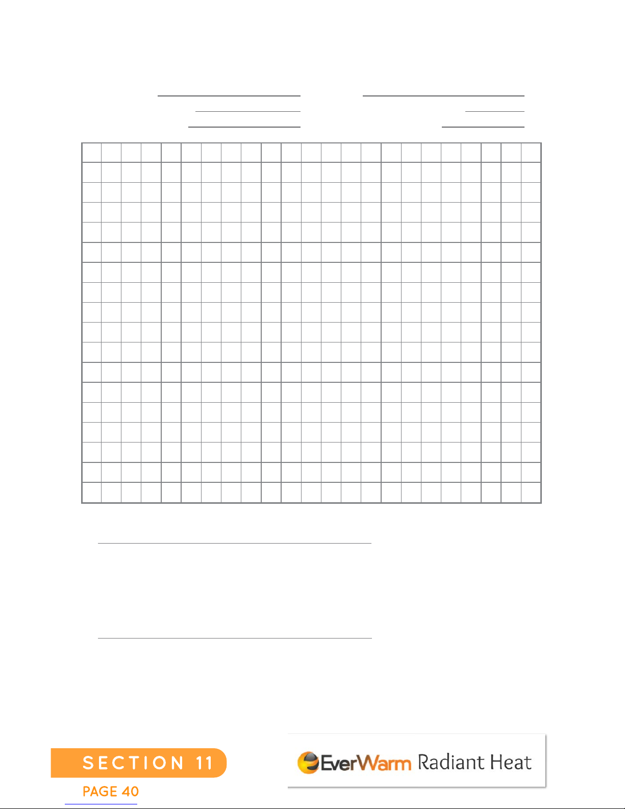
NOTES
Sub-floor:
Square Footage:
Floor Covering:
Voltage:
Calculated ohms reading:
Actual ohms reading:
FOR 120 VOLT INSTALLATIONS, USE THIS FORMULA:
Example: A typical 10’ X 10’ (100 sq-ft) room will have approximately
three sheets, for a total of 30 linear feet of Heating Film. Divide 218 by
30, yielding a calculated ohms reading of 7.27.
FOR 240 VOLT INSTALLATIONS, USE THIS FORMULA:
Example: A typical 10’ X 10’ (100 sq-ft) room will have approximately
three sheets, for a total of 30 linear feet of Heating Film. Divide 872 by
30, yielding a calculated ohms reading of 29.07.
R =
218
___
L
R =
872
___
L
 Loading...