

VC451 SOLAR-POWERED PIR CAMERA KIT
Installation and Operating Manual
What you get
The components included in the C451Solar-powered PIR
Camera Kit:
● 1 x PIR Camera with Solar Panel (VC451)
1 x Remote Control (SR103)
●
● 1 x 6V 1.2A Rechargeable Battery
1 x 9V Alkaline Battery
●
● 1 x 3V CR2032 Lithium Battery
1 x Waterproof Rubber Plug
●
● Fixing Pack and Operating Instruction
Product Layout
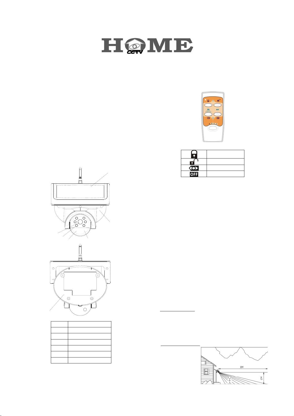
PIR Camera with Solar Panel (VC451)
7
1
2
3
1 Lens
2 Infrared LED
3 PIR Motion Sensor
4 Status LED
5 Solar Panel
6 Front Cover
7 Back plate
4
5
6
Remote Control (SR103)
Arm
Disarm
Camera on
Camera off
Introduction
The 2.4GHz Solar-powered Color PIR Camera Kit is a truly
wireless camera, receiving all of its required energy from the
sun. With no wires to run, this camera installs easily, providing
security and convenience in a simple, economical manner. Its
solar panel collects daylight and maintains a charge to the
battery of the camera during daylight hours. A negligible amount
of energy is released by the rechargeable battery to operate the
camera during nighttime.
When the camera's PIR motion sensor detects motion, images
and voices are transmitted. Upon receiving these signals, the
optional wireless receiver (VR111) will activate the VCR/DVR to
start recording, so you'll know who visits or breaks in your
property while you are away.
Caution
Pay attention to the following before you install:
1. Sufficient daylight:
during daylight hours. Please mount the camera at the location
that can receive sufficient daylight exposure.
Mount the PIR Camera at 2m height above the ground.
2. Detecting sensitivity:
detecting the
objective
movement and
heat. When the
temperature of the
1
Solar panel requires constant charge
A passive infrared sensor operates by
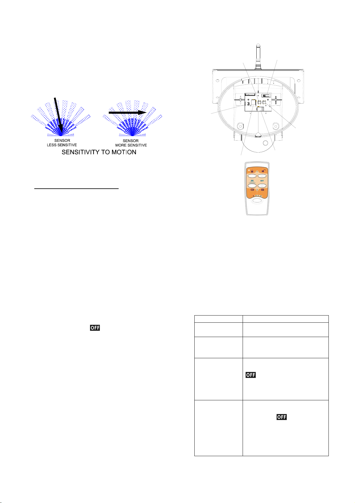
moving object and its surrounding area are close in value, it
may reduce PIR’s sensitivity. The motion detector’s infrared
beams radiate outward like the slat of a wooden fence.
Prior to mounting, keep in mind that the motion sensor is
more sensitive to the motion that crosses these “slats”, and
less sensitive to the motion that moves directly towards the
sensor.
The passive infrared sensor has a detection coverage of
80 degree at 8m away.
3. Keep a light source during nighttime:
work in total darkness. Please bear in mind the camera's
viewing area must be illuminated with a suitable light source
during nighttime.
The camera cannot
Setting
Learning the ID code
1. Undo and remove the fixing screw from the bottom edge of
the front cover. Carefully pull the front cover away from
the back plate.
2. By using either 6V/1.2Ah or 7.5V DC/300mA as its power
sources, the PIR Camera will start warming up and the
Status LED will be on steadily.
3. Press and hold the learn switch (SW1) on the rear of front
cover for more than 3 seconds until the Status LED on the
PIR Camera flashes. The PIR Camera enters the ID code
learn mode and the Status LED will flash once per second.
The user has a 30-second to emit the ID code of remote
control (SR103) to the PIR Camera.
4. Set the 4-position slide switch to ‘A’ position on the remote
control by pressing the
seconds, enabling it to emit the ID code to the PIR Camera.
5. The Status LED on the PIR Camera will be on again after
changing from flashing to illuminating for 3 seconds then off.
The ID code has been learnt successfully.
6. If failure to learn the ID code within 30 seconds, the Status
LED will flash three times rapidly before reverting to warm
up period and the Status LED will be on steadily.
button for more than 5
Learn Switch
Connector
Solar Power Jack
Channel Switch
Reset Switch
DC Adaptor Jack
Cleaning out the ID code
1. Under any mode, press and hold the learn switch (SW1) on
the rear of front cover for 3 seconds until the Status LED
flashes. Release the switch and the Status LED will flash
once every second.
2. Press the learn switch again until the Status LED is off. The
PIR Camera will revert to the last mode. The ID code has
been cleaned out entirely.
Status LED indication
The indication of Status LED on the PIR Camera may help you
judge if the ID code has been learnt properly.
Status LED indication
Enter ID code
learn mode
Fail to learn the
ID code under ID
code learn mode
ID codes have
been learnt
Up to 12 ID codes
have been learnt
2
LED flashes once per second
LED flashes 3 times rapidly before
exit
LED flashes after entering ID code
learn mode. After pressing the
button on the remote control
for 5 seconds, the PIR Camera will
exit the present learn mode and
revert to the last mode
LED flashes once per second after
entering ID code learn mode. After
pressing the
remote control, the Status LED of
PIR Camera flashes three time
rapidly before exit the present
learn mode and revert to the last
mode
button on the
Installation
p
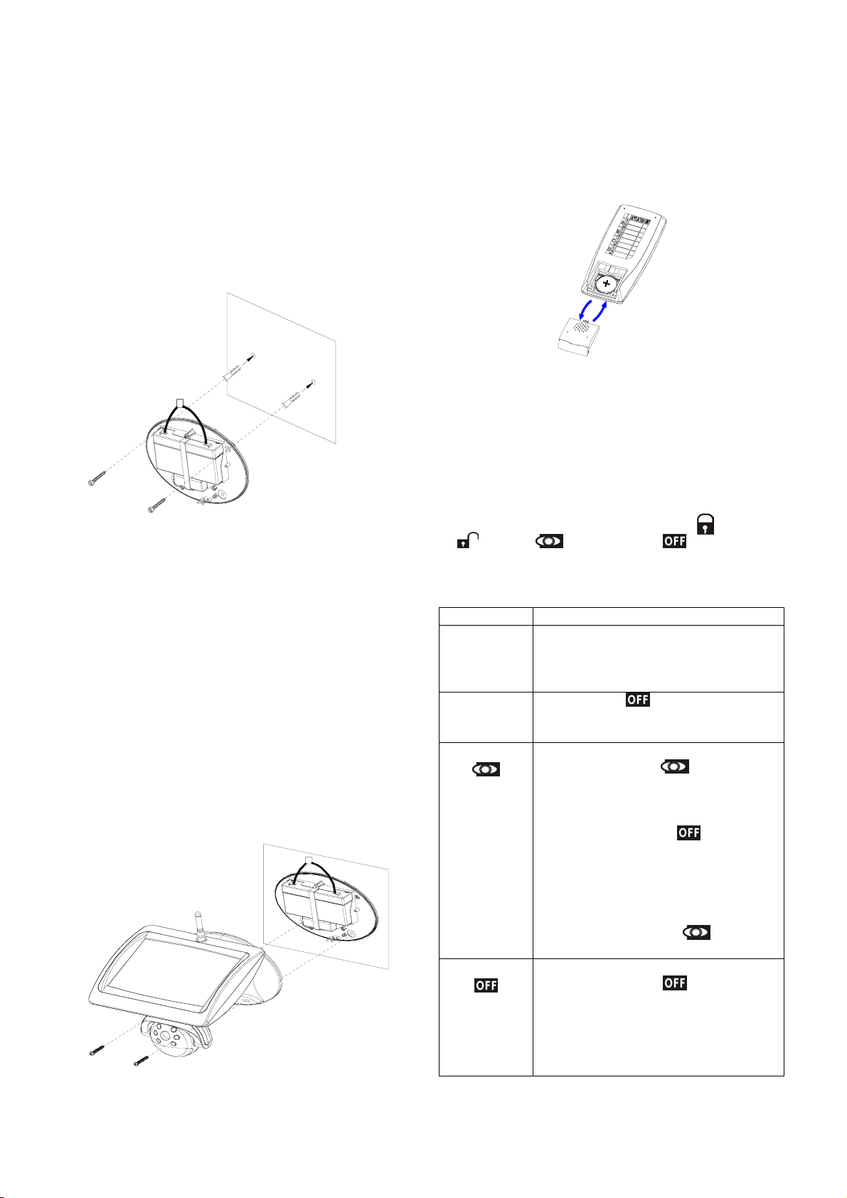
Step 1: Install the camera
Use the fixing template provided to mark the position of the
1.
four fixing holes. Drill four 5mm-diameter holes.
Mount back plate by inserting two screws into fixing holes
2.
on the top edge of back plate.
Adjust the “Channel switch” (SW3) to set up a channel.
3.
And remember which channel you selected.
4. Plug the power connector of the rechargeable battery to
the connector located on the rear of front cover.
If fitted, plug the solar panel connecting wire or DC adaptor
5.
to the solar power jack or DC adaptor jack located on the
rear of front cover.
Step 2: Install Remote Control
1. Remove the battery cover. Fit the 3V Lithium battery in the
2. By pressing any key, the red LED will illuminate, which
3. Replace the battery cover.
4. To work with the PIR Camera, it is a must to set the
The buttons’ functions are listed hereunder:
6. Secure the front cover to the back plate by inserting screws
into two fixing holes on the bottom edge of front cover and
back plate. And then insert the waterproof rubber plug into
the hole at the bottom of front cover.
compartment provided with +v terminal facing upwardly.
implies that the battery has been inserted properly.
4-position slide switch to “A” position on the remote control.
“A” position is situated in the orange background of plate,
simply follow its orange track for operating (Arm),
(Disarm), (Camera on) and (Camera off).
Button Function
4-position
slide switch -A,B,C,D
Learn Pressing the button for about 5
Camera On
Camera Off
A : controllable to PIR Camera (VC451)
B,C & D: controllable to On/Off receiver
(AN121, B410N), Dimmer Receiver
(AD121, B410D).
seconds until the Status LED is off will emit
the ID code to the PIR Camera.
When the PIR Camera is connected to a
6V/1.2Ah, press the
second on the remote control will enable
the operation of image and voice signal on
the PIR Camera but will disable recording
signal. Fail to press the
1 minute will disable the operation of image
and voice signal on the PIR Camera.
If a 7.5V DC/300mA is in use, the image
and voice signal on the PIR Camera will be
always transmitted, the
not work for this instance.
When the PIR Camera is connected to a
6V/1.2Ah, press the
second will disable the operation of image
and voice signal and send a stop recording
signal to the wireless receiver (VR111).
When a 7.5V DC/300mA is in use,
button for one
button within
button for one
button will
ress
3
 Loading...