


TSC06-X
Wireless IP Gateway
User Manual
Version: 1.0
Date: 2016-07-27

TSC06-C Gateway User Manual
Table of Contents
1. Copyright and Confidential ................................................................................. 1
2. Disclaimer ............................................................................................................. 1
3. Revision Record .................................................................................................... 1
4. Introduction .......................................................................................................... 2
5. Overview ............................................................................................................... 2
5.1. Sockets .............................................................................................................. 2
5.2. Buttons .............................................................................................................. 3
5.3. LED ..................................................................................................................... 4
5.3.1. Power LED ..................................................................................................... 4
5.3.2. Connection LED ............................................................................................ 4
5.3.3. Network 1 LED ............................................................................................. 5
5.3.4. Network 2 LED ............................................................................................. 5
5.4. USB .................................................................................................................... 5
6. Specification ......................................................................................................... 7
6.1. Power function ................................................................................................. 7
6.2. RF function ........................................................................................................ 7
7. How to search the device? ................................................................................. 7
8. Web Configuration ............................................................................................... 9
8.1. Network Settings ........................................................................................... 10
8.2. System Settings ............................................................................................. 12
8.2.1. NTP Settings ............................................................................................... 13
8.2.2. Gateway Registration ................................................................................ 14
8.2.3. U-Net Message Forward ........................................................................... 14
8.3. VPN Settings ................................................................................................... 15
8.4. Language Settings ......................................................................................... 18
8.5. Update Settings .............................................................................................. 19
8.5.1. In Linux Runtime ....................................................................................... 20
8.5.2. In the Boot Time ........................................................................................ 21
9. U-Net Bind .......................................................................................................... 22
10. Warnning ......................................................................................................... 23

TSC06-C Gateway User Manual
1. Copyright and Confidential
The information contained in this document or diagram is confidential and
proprietary to Chromagic Technologies Ltd. Co. This information may not be
distributed or used for any purpose other than the evaluation of Chromagic’s
solutions, nor may it be disclosed to any party without the prior written consent
from Chromagic. All Rights Reserved.
2. Disclaimer
This document or diagram and the information contained herein is provided on
an "AS IS" basis and Chromagic DISCLAIMS ALL WARRANTIES, EXPRESS OR
IMPLIED, INCLUDING BUT NOT LIMITED TO ANY WARRANTY THAT THE USE
OF THE INFORMATION HEREIN WILL NOT INFRINGE ANY RIGHTS OR ANY
IMPLIED WARRANTIES OF MERCHANTABILITY OR FITNESS FOR A
PARTICULAR PURPOSE.
3. Revision Record
Date Version Description
2016-07-25 1.0 The first release.
Page 1 of 25
TSC06-C Gateway User Manual
Connect
Dummy
4. Introduction
The gateway is a transceiver which belongs to the member of U-Net series and
is fully compatible with any U-Net enabled devices. It can reliably and
remotely control and monitor your U-Net enabled devices. Whether you be on
site and log in through your network, or away from the premises while logging
in through the internet, you’ll always have access to control and monitor your
security system. You can achieve a better control of your home security to
make your home safer than ever before.
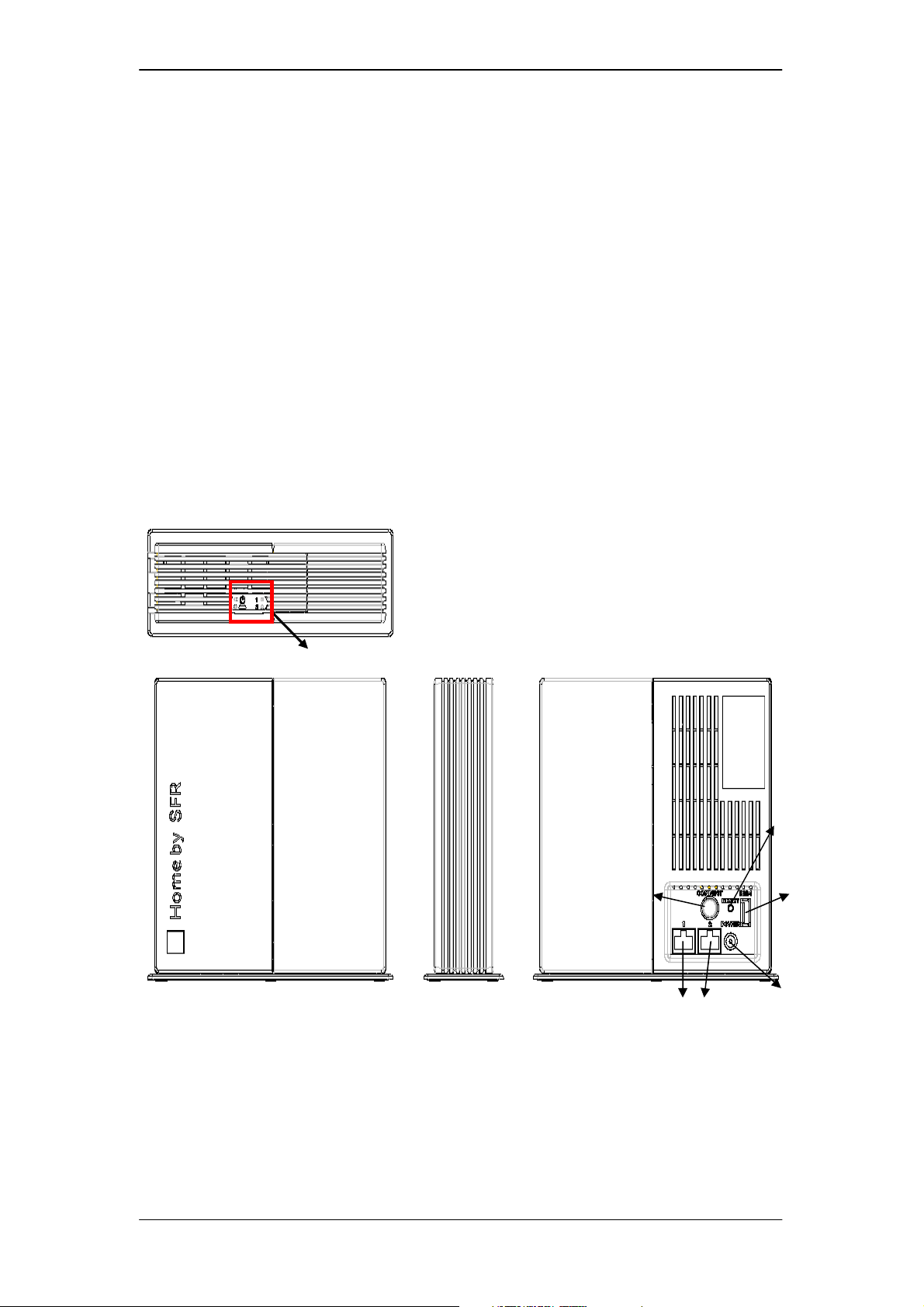
5. Overview
LEDs
Figure 1: The overview of TSC06-C
5.1. Sockets
button
RJ45
Reset
USB
DC Jack
DC Jack:
Input the DC power voltage 9V and current 2A.
Page 2 of 25

TSC06-C Gateway User Manual
RJ-45 Socket:
There are two RJ-45 sockets. TSC06-C has the Ethernet hub function.
These two sockets are linked. In SFR, one will connect to SFR modem;
another will connect to SFR mini hub.
5.2. Buttons
There are two buttons on TSC06-C: one is the reset button (near the dummy
USB socket), and another is the connection button (near the RJ-45 socket).
Reset Button:
This button will reboot the system. If the system is halting, the user can
press this button.
Note: TSC06-C has a battery inside its body. If the DC power is cut off, the
unit will automatically switch to the battery power. As a result, the device
would be still halting and need to be reset.
Connection Button:
Enable the firmware upgrade function in boot time.
After pressing the reset button or powering on the device, press the
connection button for more than three times. To ensure the function is
enabled, please check the connection LED is blinking in red and green.
Set all settings of the device to factory default.
After pressing the reset button or powering on the device, press and
hold the connection button until the connection LED turns on the red
and green light and then turns off. Then release the connection
button.
Manually enable the bind function.
After the system boots up, press the connection button once.
Manually cancel the bind function.
When the system is in the binding mode, press the connection button
once.
Page 3 of 25
TSC06-C Gateway User Manual
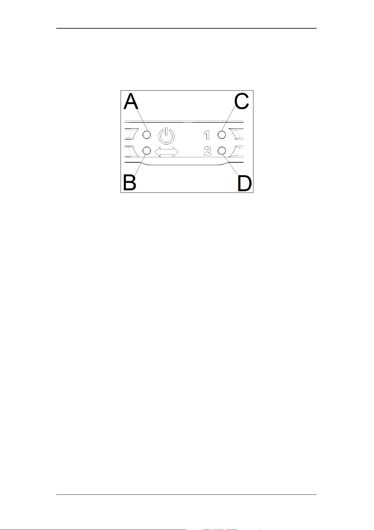
5.3. LED
Figure 2: The definition of the LEDs.
The function & name of these LEDs:
LED A: Power LED.
LED B: Connection LED.
LED C: Network 1 LED.
LED D: Network 2 LED.
5.3.1. Power LED
The green light is on:
The power is on.
The orange light is on:
The Flash is writing data.
The orange light flashes once every 5 seconds:
The system time is not synchronized after boot up.
5.3.2. Connection LED
The green light is on:
The connection to the server is successful.
The red light is on:
Page 4 of 25

TSC06-C Gateway User Manual
The DHCP function is enabled but couldn’t get the IP information.
Blinking in red and green:
The firmware upgrade function is enabled in bootloader runtime.
The green light is blinking in second: (0.5s On, 0.5s Off)
The system is in the binding mode.
The green light is turn on 2 seconds and turn off 2 seconds:
The system’s inclusion of other U-Net device is successful.
The green light is blinking: (0.1s On, 0.1s Off)
If the system binding exceeds time limit, it will persist for 4 seconds.
If the system is aborting binding mode, it will persist for 1 second.
The green light and the red light are blinking 3 times (Orange):
The system boots up OK.
5.3.3. Network 1 LED
The green light is on:
The RJ-45 socket 1 is connecting.
The green light is flash:
The RJ-45 socket 1 is in active
5.3.4. Network 2 LED
The green light is on:
The RJ-45 socket 2 is connecting.
The green light is flash:
The RJ-45 socket 2 is in active
5.4. USB
There are four USB sockets. One is dummy socket on the side of the body, and
the other USB sockets are inside the box. In SFR, the dummy USB will provide
Page 5 of 25

TSC06-C Gateway User Manual
the power to the mini hub. USB sockets 2&3 can be used for plugging the 3G
dongle. USB 4 is only for power supply.
Page 6 of 25

TSC06-C Gateway User Manual
6. Specification
6.1. Power function
1. Operating temp:-10~40℃
2. Operating Humidity:85%(maximum,relative humidity)
3. Storage temp:-20~60℃
4. Input:adapter:9V/battery:6V
5. Battery type:rechargeable battery 2100mA
6. Adapter: INPUT :AC100~240V 50/60Hz 0.5A
OUTPUT:DC 9V 2000 mA
7. DSL USB power:
(1) this connection can use DSL USB output voltage
(2) Need to be able DSL provides voltage to 9V
(3) DSL USB power can charge battery
8. Low power detect: Gateway must detect for low battery and report to server
6.2. RF function
1. RF Compatibility:
Protocol Stack : U-Net 4.0
Profile: Home Automation Security
2. Frequency range:916.00MHz
3. Modulation: FSK
4. Coverage Range :Free Space 100M
5. RF Antenna: The gateway uses built-in antenna
7. How to search the device?
In default, TSC06-C will enable the DHCP function to get the IP address. If the
DHCP function failed, you will see the “Connection LED” lights up in red. In this
case TSC06-C will set the IP address to default 192.168.1.222.
Static IP: 192.168.1.222
Page 7 of 25

TSC06-C Gateway User Manual
Netmask: 255.255.255.0
Gateway: 192.168.1.1
DNS1: 192.168.1.1
Otherwise TSC06-C will get the IP address from the DHCP server, and you can
use the utility “Gateway Finder” to find out the assigned IP address.
The “Gateway Finder” is designed with .Net Framework; you must install .Net
Framework (can be downloaded freely) in your system first.
Execute the “GatewayFinder.exe”.
Figure 3: Gateway Finder
Just click the “Search” button, and you will find out TSC06-C IP address.
Figure 4: Gateway Finder Find Out the IP Address
If it can’t get a response within about 5 seconds, it will show timeout.
Figure 5: Gateway Finder Timeout
Page 8 of 25

TSC06-C Gateway User Manual
8. Web Configuration
Use the browser (IE or Firefox) to access TSC06-C. Just enter the URL
http://(IP Address)/ in your browser. For the first time access of TSC06-C web
server, you will be requested to login. The default user name is “webadmin” and
the password is “admin”.
Figure 6: First Time Access of TSC06-C Web Server.
Page 9 of 25

TSC06-C Gateway User Manual
8.1. Network Settings
Set the IP address using the DHCP or the static IP address.
Figure 7: Network Settings DHCP
Click the “Manual Setting the IP address” item to set the static IP address.
Figure 8: Network Settings DHCP
Page 10 of 25

TSC06-C Gateway User Manual
After setting OK, don’t forget to press the “submit” button.
Figure 9: Network Setting Submit
After 20 seconds, the browser will connect to new IP address.
And you must re-login.
Figure 10: Browser Auto Connect to New IP Address
Page 11 of 25

TSC06-C Gateway User Manual
Figure 11: The Browser Connected to New IP Address
8.2. System Settings
The system settings will set the NTP function and the message server.
Figure 12: System Settings
Page 12 of 25

TSC06-C Gateway User Manual
8.2.1. NTP Settings
TSC06-C does not have RTC (real-time clock). That means if the power is off,
the system time will be reset or stopped.
So at the boot time, TSC06-C will synchronize the system time with the NTP
server.
The default NTP settings:
NTP function enable: Yes
NTP Server: clock.via.net
Time Zone: 0
If TSC06-C failed to connect to the NTP server, it will try again after 1 hour.
If time synchronization is OK, after 4 hours it will synchronize again.
After boot up, if TSC06-C detects the system time is not correctly synchronized,
the power LED will flash once every 5 seconds.
The user can set the NTP settings from the browser.
Figure 13: System Settings
Page 13 of 25

TSC06-C Gateway User Manual
8.2.2. Gateway Registration
If this function is enabled, after boot up TSC06-C will send the registration
information to the server every 150 seconds.
Figure 14: System Setting Gateway Registration
8.2.3. U-Net Message Forward
If this function is enabled, when the U-Net devices report the state to TSC06-C,
it can forward the message to the server.
Page 14 of 25

TSC06-C Gateway User Manual
Figure 15: System Setting Message Notification
8.3. VPN Settings
A VPN (Virtual Private Network) is a network that uses a public
telecommunication infrastructure, such as the Internet, to provide remote
offices or individual users with secure access to their organization's network.
Figure 16: The VPN link.
TSC06-C will use the OpenVPN to provide the VPN function.
The user can see the OpenVPN state or settings from the browser.
Page 15 of 25

TSC06-C Gateway User Manual
Figure 17 VPN Settings
There are two secret keys in OpenVPN: one is for OpenVPN and the other is for
OpenSSL. The keys do not store in the Linux file system. They will be stored in
the Flash, and encrypted.
Before running OpenVPN, these keys must have existed. The user can upload
the key in the “Update” page. Just upload the key file instead of the firmware
file.
Figure 18: Upload the Key File
Page 16 of 25

TSC06-C Gateway User Manual
Figure 19: Upload Key OK
If the VPN function is enabled and established. The connection LED will turn
green light on.
Page 17 of 25

TSC06-C Gateway User Manual
8.4. Language Settings
Change the language of the web page display.
Figure 20: Language Settings
Figure 21: Language Changed to French.
Page 18 of 25

TSC06-C Gateway User Manual
Figure 22: Language Changed to Chinese
8.5. Update Settings
There are two firmware upgrade functions in TSC06-C. One is in the bootloader
runtime; another is in the Linux runtime. Normally, the user always upgrades
the firmware in the Linux runtime, unless the system encounters error or the
user wants to manually enable the upgrade function. In these cases it will
operate in the bootloader runtime.
Page 19 of 25

TSC06-C Gateway User Manual
8.5.1. In Linux Runtime
Figure 23: The Upgrade Page in the Linux Runtime
Choose the firmware file and click the “Update” button. It will start to upload
the firmware and write to the flash. The system will start to count down. At this
time the user should not cut off the power of TSC06-C.
Figure 24: Upgrade and Count Down to Reboot.
Page 20 of 25

TSC06-C Gateway User Manual
After the count down, the browser will automatically re-connect to the
homepage of TSC06-C.
When the firmware is writing to the Flash, the power LED will turn on red light.
8.5.2. In the Boot Time
In the boot time, if TSC06-C found error image that causes boot failure,
TSC06-C will automatically enter the upgrade mode. At this moment, the
connection LED will flash green and red light alternately.
You can manually turn to upgrade mode in boot time. Press the reset button,
and then press the connection button over three times. Check the connection
LED to make sure TSC06-C successfully enters the upgrade mode.
Use the browser to connect to 192.168.1.222.
Figure 25: The upgrade page in the bootloader runtime.
Choose the firmware file and click the “Mettre a jour” button. It will start to
upload the firmware and write to the flash. It will start to count down. At this
time, the user should not cut off the power of TSC06-C.
Page 21 of 25

TSC06-C Gateway User Manual
Figure 26: The count down in the bootloader runtime.
After the count down, the browser will re-connect to 192.168.1.222. But if
TSC06-C has enabled the DHCP function, the IP will be changed and the user
needs to connect to the newest IP manually.
9. U-Net Bind
The binding is an operation of the U-Net. It is for including other U-Net devices
to TSC06-C.
The following will describe how to use the connection button to operate the
binding function.
Start binding:
Push the connection button once. The connection LED will start to blink
green light.
Bind device:
Let other U-Net device start binding. For example: the SR801, press the
disarm key and hold over three seconds. If the binding is successful, the
connection LED of TSC06-C will stop blinking. It will turn on for 2 seconds,
and then turn off for 2 seconds.
Cancel binding:
In the binding mode, when the connection LED is blinking, push the
connection button again, and the connection LED will flash quickly. The
Page 22 of 25

TSC06-C Gateway User Manual
binding will be cancelled.
Binding timeout:
If the system stays in binding mode for over 30 seconds, timeout will occur.
The connection LED will quickly flash for 4 seconds.
The user can read the device information from the browser.
e.g.: http://192.168.1.100/unet/deviceinfo.cgi?uid=0
It will list all device information in TSC06-C.
0200 OK uid=0
--device
uid=2
type=7:Remote
code=7124/7801/7803/7128
subcode=0000
rssi=3
battery=0
mac=01:90:02:04:0F:00:00:30
partialarm=0:0
alias=Remote
posx=0
posy=0
width=0
height=0
entrydelay=0
10. Warnning
Federal Communication Commission Interference Statement
This equipment has been tested and found to comply with the limits for a Class B
digital device, pursuant to Part 15 of the FCC Rules. These limits are designed
to provide reasonable protection against harmful interference in a residential
installation. This equipment generates, uses and can radiate radio frequency
energy and, if not installed and used in accordance with the instructions, may
cause harmful interference to radio communications. However, there is no
guarantee that interference will not occur in a particular installation. If this
equipment does cause harmful interference to radio or television reception,
Page 23 of 25

TSC06-C Gateway User Manual
which can be determined by turning the equipment off and on, the user is
encouraged to try to correct the interference by one of the following measures:
- Reorient or relocate the receiving antenna.
- Increase the separation between the equipment and receiver.
- Connect the equipment into an outlet on a circuit different from that to which
the receiver is connected.
- Consult the dealer or an experienced radio/TV technician for help.
This device complies with Part 15 of the FCC Rules. Operation is subject to the
following two conditions: (1) This device may not cause harmful interference,
and (2) this device must accept any interference received, including interference
that may cause undesired operation.
FCC Caution: Any changes or modifications not expressly approved by the party
responsible for compliance could void the user's authority to operate this
equipment.
this transmitter must not be co-located or operating in conjunction with any other
antenna or transmitter.
Specifications
Operating temperature range -10°C to 40°C
Operating humidity 85% RH at 30°C
Adapter DC9V 2A
Battery type Li-ion cell 2100mAh 6V
Transmission range Outdoors >100m (Open space) for front
and sides
Frequency range 916 MHz(US/Israel)
WARNING:
Do not dispose of electrical appliances as unsorted municipal waste, use separate
collection facilities instead. Please contact your local government for information
regarding the collection systems available.
If electrical appliances are disposed of in landfills or dumps, hazardous substances
can leak into the groundwater and get into the food chain, damaging your health and
well-being.
When replacing old appliances with new once, the retailer is legally obligated to take
back your old appliance for disposal at least for free of charge.
Everspring Industry Co., Ltd.
www.everspring.com
3F., No.50, Sec. 1, Zhonghua Rd., Tucheng Dist., New Taipei City 236, R.O.C
Page 24 of 25

TSC06-C Gateway User Manual
Page 25 of 25
 Loading...