

Everspring Industry Co ST113, SE802, SA802 User Manual

SOLAR-POWERED POOL ALARM SYSTEM FOR SAFETY AID
TO READ ATTENTIVELY AND TO PRESERVE FOR FUTURE CONSULTATION
WARNING
This system is simply a safety aid which announces a danger (or risk of danger) when an
equivalent of 8kgs (18 pounds) object falls into a unsupervised swimming pool. The fast
intervention in less than 3 min of a responsible adult is obligatory when the signal of alarm
happens. Ensure the construction of the pool wall is solid enough, thus it can stand the drilling
of the screws and wall plugs without cracking the pool wall. After installation, ensure the pool
alarm itself cannot be shaken, otherwise it will affect the performance of pool alarm detection. In
the event of any injury or death to any person arising out of misuse, abuse, negligence, accident
or alteration, Everspring Tech USA, Inc., will not be liable for any consequence caused.
This system does not replace the good direction nor with the several liability. The purpose of it is
not to either replace the vigilance of the parents and/or the responsible adults, which remains the
essential factor for the protection of the children with less than five years;
The user who turns OFF the system must be conscious that the human monitoring must take
over;
It is imperative to react when the signal of alarm happens;
The greatest vigilance of the responsible parent /adult is necessary between the end of the bathe
and the reactivation of the product;
Never leave children unattended in or aro und the s wimmin g pool or spa. Children under five years of
age are at the greatest risk for in jury or death i n pool-rel ated acc idents.
In the event of possibility of stroke with against current: "Cancel the stroke with against current at
the end of the bathe to allow the reactivation of the product".
Some of cleaning robots as a plunger robots type are incompatible with the systems of detection
of immersion
1
PRODUCT LAYOUT
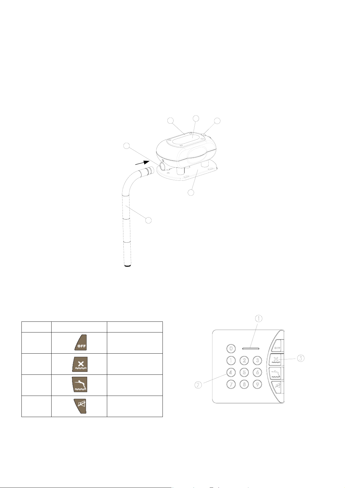
Solar-powered Wireless Pool Alarm (ST113)
Battery Cover
Solar Panel
Start Button
Base
Sensing Compartment
Detachable Tube
Wireless Keypad (SA802)
Setting/Low Battery LED
1
5
6
2
4
3
Keypad
Function Key
Sequence
1
2
3
4 Disarm the alarm
Function Key Description
System Off
System On
Auto
sound
2
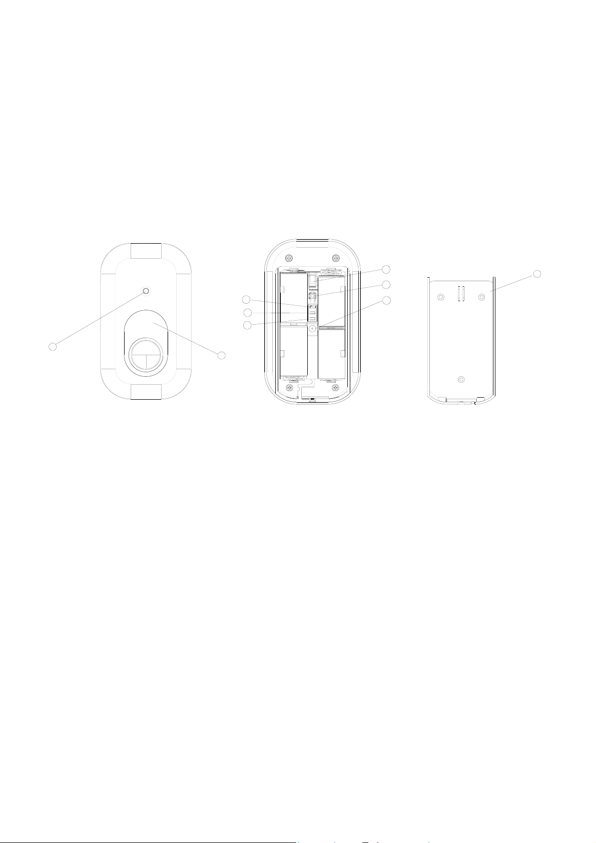
Siren & Strobe (SE802)
Strobe Light
Red & Green LED ( when both LEDs are on, the LED will be converted into orange color)
Tamper Switch
Learning Key
DC Jack
Two-Phase Sound Jumper Link
Anti-jamming Jumper Link
Tamper Jumper Link
Mounting Bracket
3
4
6
7
8
2
1
5
9
The kit includes one piece each of Solar-powered Wireless Pool Alarm, Siren & Strobe and Wireless
Keypad, all of which products have been designed to aid in the detection of unwanted intrusions into
unclosed above ground or in ground swimming pools. THE SOLAR-POWERED WIRELESS POOL
ALARM IS NOT A LIFE SAVING DEVICE. It should be used along with other safety equipment and
precautions. It is intended to provide an additional level of security to your swimming pool and/or spa. This
unit is not intended to replace any other safety consideration : adult supervision, lifeguards, fences, gates,
pool covers, locks, and so forth… And some devices may not detect gradual entry.
INTRODUCTION
The solar-powered pool alarm is an electronics device that, in armed mode, automatically sounds an
alarm when children or pet fall into your unsupervised pool. Entry into the above ground/in ground pool
will be detected by the unit’s electronics sensor, triggering a loud pulsating alarm.
Apart from it, the pool alarm is also compatible with our U-Net series, serving as a transceiver.
PACKAGE CONTENT
The solar-powered wireless pool alarm system is packaged in a gift box that minimizes the chance of
damage due to handling. The contents of the package include the following items:
3

Solar-powered
Item Qty
Base
Initiation key 2
LR20 Alkaline Battery
Solar Panel with Ni-MH AA 6V
Rechargeable battery
Detachable tube
(φ4.7x30mm) Screw
Plastic wall plug 4
Siren & Strobe (SE802) 1
(φ3 x 18mm) Screw
Plastic wall plug 3
1.5V LR14 14A Size C 4
Wireless Keypad (SA802) 1
(φ3 x 18mm) Screw
1
4
1
4
4
3
2
wireless pool alarm
system(ST113)
3
3
3
3
3
3
3
3
3
3
3
3
3
Plastic wall plug
Operating instruction manual
2
1
3
3
SOLAR-POWERED WIRELESS POOL ALARM
INSTALLING THE POOL ALARM
There are four detachable tubes which can be jointed to a long tube. The length of tube depends on water
level in the pool. The distance from the bottom end of tube to water level must be greater than
24.5cm. (9.7 inch) A power drill and screwdrivers are needed for installation. Note: The unit may not
function properly if your pool’s water level is not maintained within the required levels of your device.
4
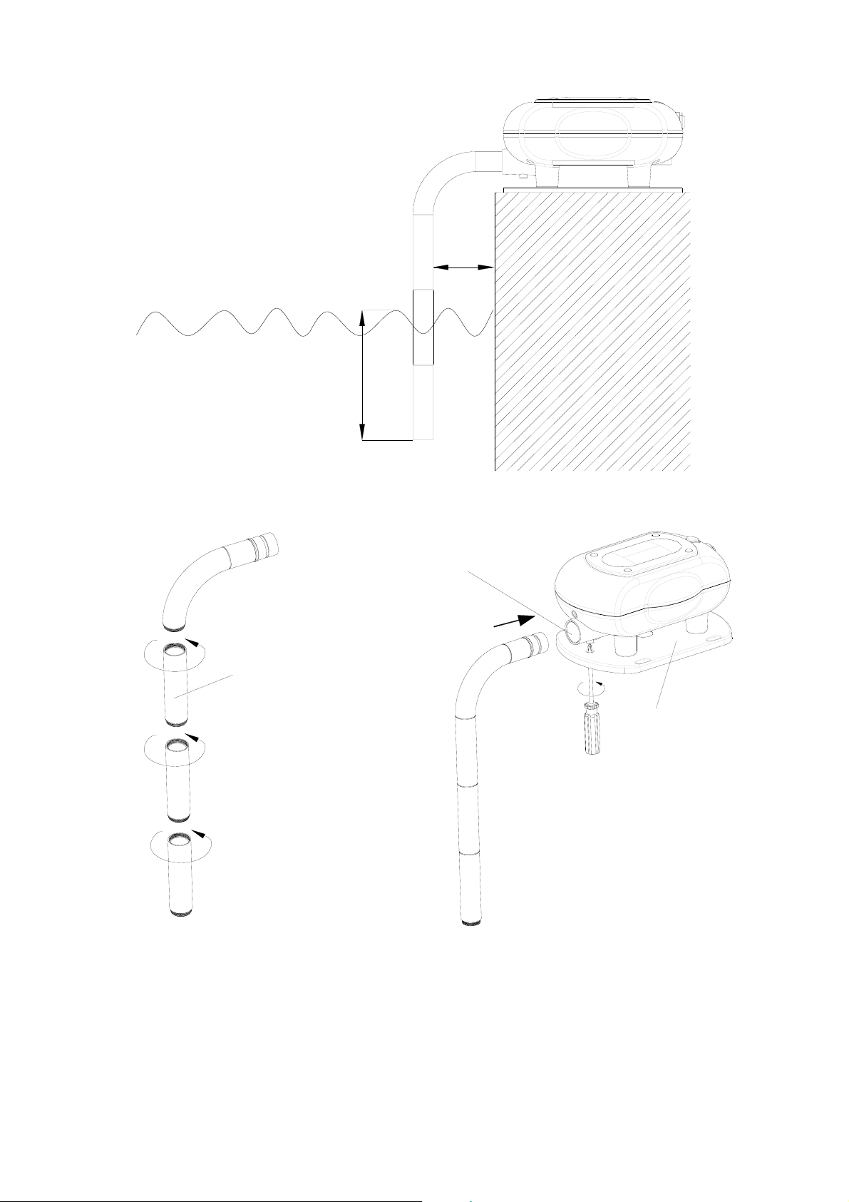
4.5cm
Under Water level
24.5cm
Sensing Compartment
Tube
Base
1. Locate the appropriate (plain and not very grassy) place to fix the unit on the top rail of the swimming
pool.
For the above ground pool, the unit must be installed at a height of 1.5m (59 inch) above the ground.
2. Joint the number of tubes according to actual water level as measured.
3. Insert the tube to the sensing compartment by fastening it through the base using the screw provided.
5
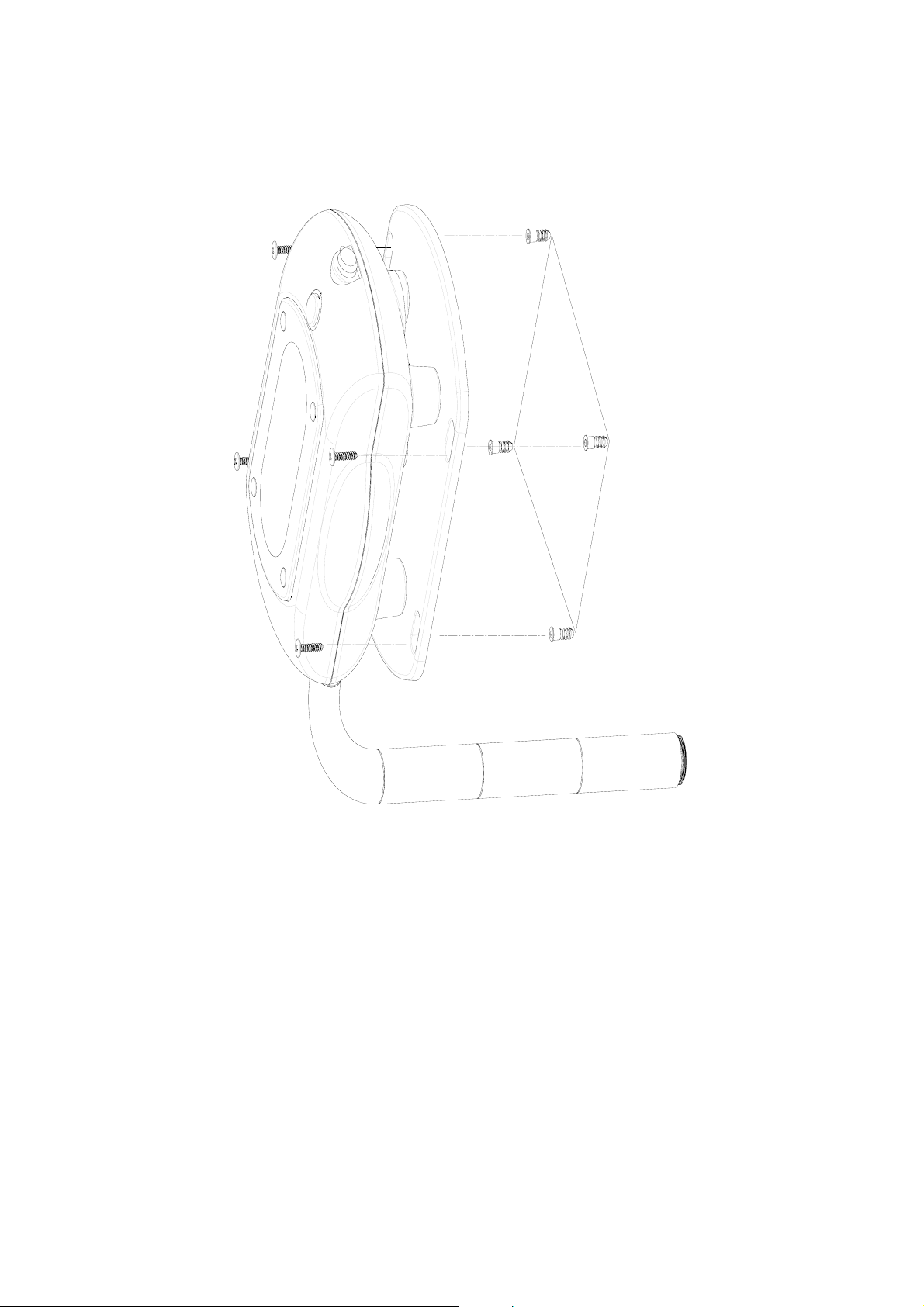
4. Use the base as a template to mark the position of four fixing holes. Drill four 30mm fixing hole and
fit the plastic wall plugs to the holes.
5. Aim the base to the place where four plastic wall plugs are situated. Fasten the base using the fixing
screws supplied.
)
H
C
N
I
5
7
.
5
(
M
C
6
.
4
1
)
H
C
N
I
6
1
.
7
(
M
C
2
.
8
1
LOADING THE BATTERY
Caution:
- use only the alkaline batteries as those provided.
- do not use out-of-date batteries (respect the expiry date),
- do not throw your old batteries in a dustbin : they contain toxic products, which are dangerous for the
environment. You must deposit them in vats envisaged for this purpose that you will find in great surfaces,
retailers, town halls...
Follow the below steps in sequence to load the batteries.
1. Remove four rubber stoppers and undo four fixing screws from the battery cover.
2. Open the battery cover and insert 4 x 13A LR20 1.5V alkaline batteries.
3. Plug the power supply cord to the DC jack.
6
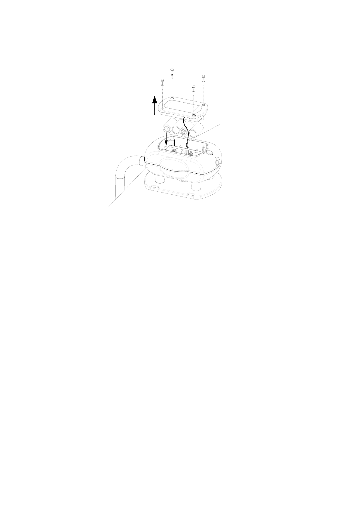
4. Replace the battery cover and fixing screws. Refit the rubber stoppers.
Note: Reverse battery cover cannot fit to the compartment.
Power Cord
DC Jack
WIRELESS KEYPAD
The Wireless Keypad is used to control the Pool Alarm by using a four digit Administrator password. The
Keypad is powered by 3 x AA 1.5V alkaline battery. Under normal operating conditions this will provide
an expected life in excess of 1 year. When the battery level falls below an unacceptable level, the
“Setting/Low Battery” LED on the front of the Keypad will flash 4 times when pressing any key. When this
occurs the batteries should be replaced as soon as possible.
POSITIONING THE KEYPAD
The Keypad should be mounted in a position close to the main entrance door so that the Administrator
password can be entered easily.
Ensure that the position selected for the Keypad is within the effective range of the solar-powered
wireless pool alarm.
Note: DO NOT fix the Keypad to metalwork or locate the unit within 1m of metalwork (i.e. radiators, water
pipes, etc) as this could affect the radio range of the Keypad.
INSTALLING AND CONFIGURING THE KEYPAD
1. Undo and remove the fixing screw from the bottom edge of the Keypad and remove the wall mounting
bracket.
7
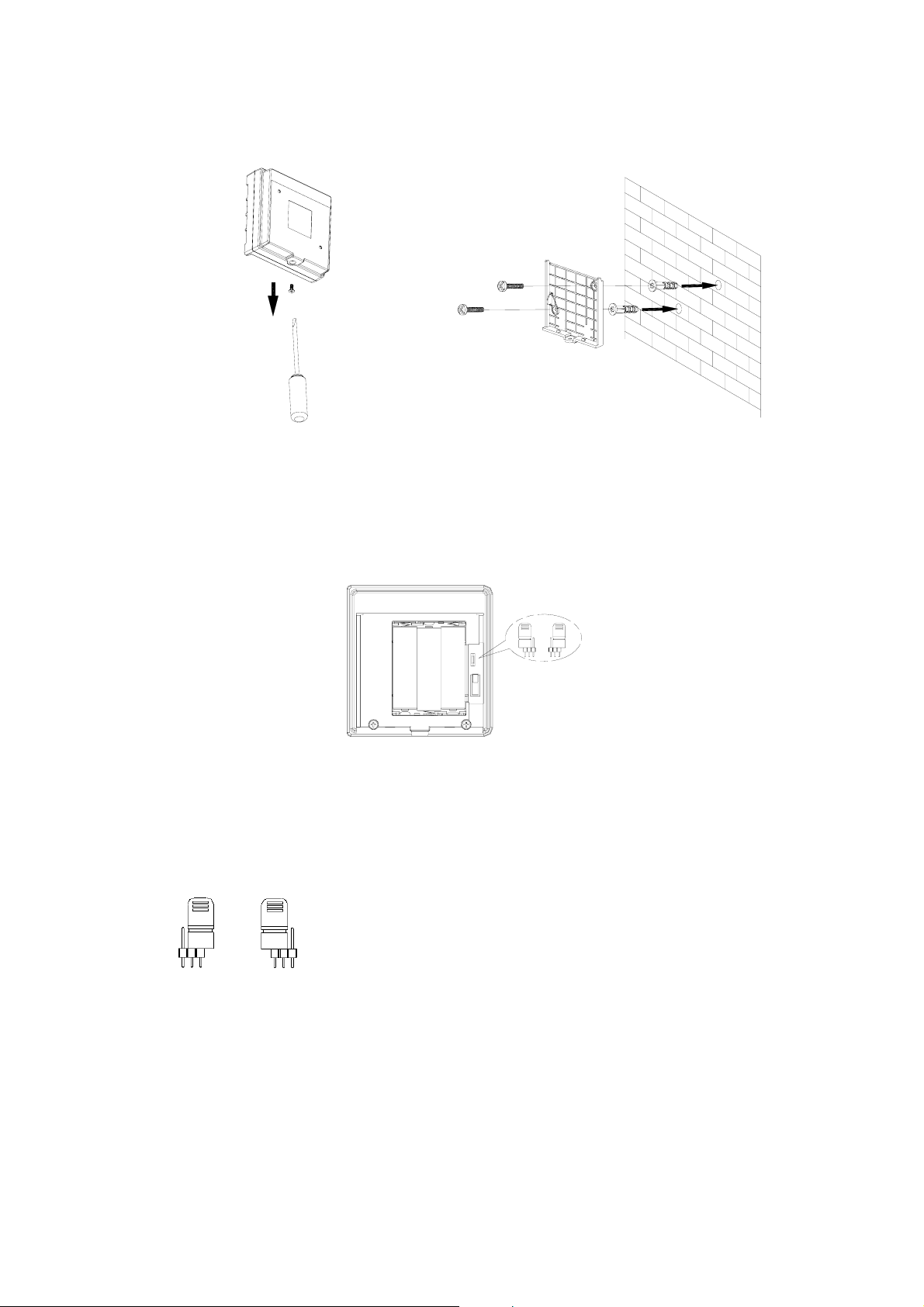
2. Using the mounting bracket as a template, mark the positions of the two fixing holes on the wall.
3. Fix the mounting bracket to the wall using the screws and wall plugs provided. Do not over-tighten
the fixing screws as this may distort or damage the mounting bracket.
4. There is one jumper link located above the battery compartment.
Jumper link J1: Reset to Factory default
If unfortunately you forget the Administrator password, reset the Administrator password to factory
default by proceeding with the following steps in sequence:
(1) Remove the batteries.
(2) Set the Jumper link J1 to off position as shown on Fig. a.
1
2
3
1
2
3
OFF ON
Fig. a Fig. b
(3) Refit the batteries. The keypad is reset properly by flashing back light 0~9 3 times.
(4) Set the Jumper link J1 to on position as shown on Fig. b.
5. Connect the 3 x AA alkaline batteries to the battery compartment.
6. Click the Keypad to the mounting bracket and screw the fixing screw. Do not over-tighten the fixing
screw.
8
 Loading...