

Everspring Industry Co SP817 User Manual
SP81
7 MOTION DETECTOR
The SP817 Motion Detector is a Z-WaveTM enabled device which is fully compatible with any Z-WaveTM
enabled network. The device can be set up in a Z-wave network to communicate directly with other end
devices such as lighting controllers, or to report directly to a Z-wave controller (usually a gateway).
The Motion Detector is designed with two detecting sensors, Passive Infra-Red (PIR) sensor and light
sensor, in order to fulfill the purpose of security and home automation. When the detector is cooperated
with security appliances, it is acting as a security device by detecting changes in infra-red radiation levels.
If a person moves within or across the device field of vision, a trigger radio signal will be transmitted to
cause full alarm condition in order to frighten intruders away. Alternatively, when the detector is worked
with home automation appliances, the detector can be set to perform the role of home automation device
by detecting both changes in infra-red radiation levels and percentage of lux levels. Once night falls,
the percentage of ambient illumination is lower than preset value. If a person moves within or across the
device field of vision, a trigger radio signal will be transmitted so as to turn on the connected lightings for
better illumination.
The PIR Detector adopts a CR123 3.0V Lithium battery which under normal conditions will have typical
life in excess of 1 year. When the battery level drops to an unacceptable level,,the detector will emit
Battery report to the Z-wave controller. When this occurs the batteries should be replaced as soon as
possible.
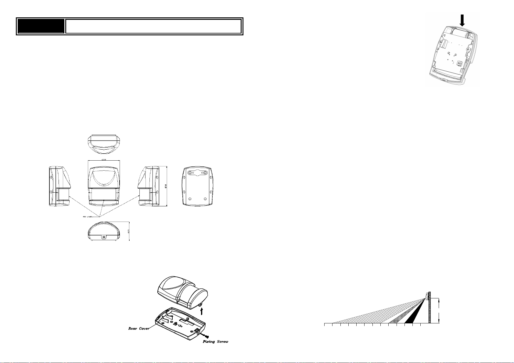
Product Overview
Adding to Z-Wave
Auto Inclusion
The detector supports Auto Inclusion feature where it will automatically enter Inclusion mode when first
powered up after a factory reset.
1. Use a screwdriver to detach the rear cover.
TM
Network
2. Put a Z-Wave Controller into inclusion mode.
3. Insert 1 CR123 3V batteries to the battery compartment with
the correct polarity. The LED on the device should turns ON..
4. The Inclusion process should be completed when the LED stops blinking.
5. Do not refit the rear cover yet.
Note: If Auto Inclusion fails, refer to the Troubleshooting section regarding Manual Inclusion.
Testing
Warm-Up
It will take approximately 2 minutes to warm up for the detector after battery is inserted. During this period
the LED behind the lens will turn on When the red LED turns off, it implies warm-up procedure is
completed and the detector is ready for detection.
- This will not affect the Inclusion/Exclusion process.
- After removing batteries, wait for 5 seconds to refit batteries.
Quick Test
1. With the tamper switch not being pressed after inclusion,,the unit will enters Test mode to allow the
user to test the device before it is mounted on the wall.
2. During Test mode, if movement is detected, the LED on the detector will light up once implying the
unit is working properly, and retrigger time is about 5 sec.
3. To exit the Test mode, simply press the Tamper switch for more than 10 seconds to enter Normal
mode.
4. During normal mode, when PIR is triggered, the red LED will not light up and retrigger time is based
on set up value.
Mounting the Detector
Choosing the location
The PIR Detector is suitable for mounting in dry interior locations only.
The recommended position for a PIR Detector is in the corner of a room mounted at a height between 1.8
and 2m. At this height, the detector will have a maximum range of up to 9m with a field of view of 110°,
subject to the position for the PCB being set in 5. (FIGURE 1&2) The position of the PCB inside the PIR
can be set to 5 different positions to adjust the range of the detector. Setting the PCB in position 3 will
reduce the range to 6m approximately, with position 1 providing a range of 3m approximately. The
recommended position setting for the PCB is in position 5.
13
FIGURE 1
23456789101112
2M
1
0
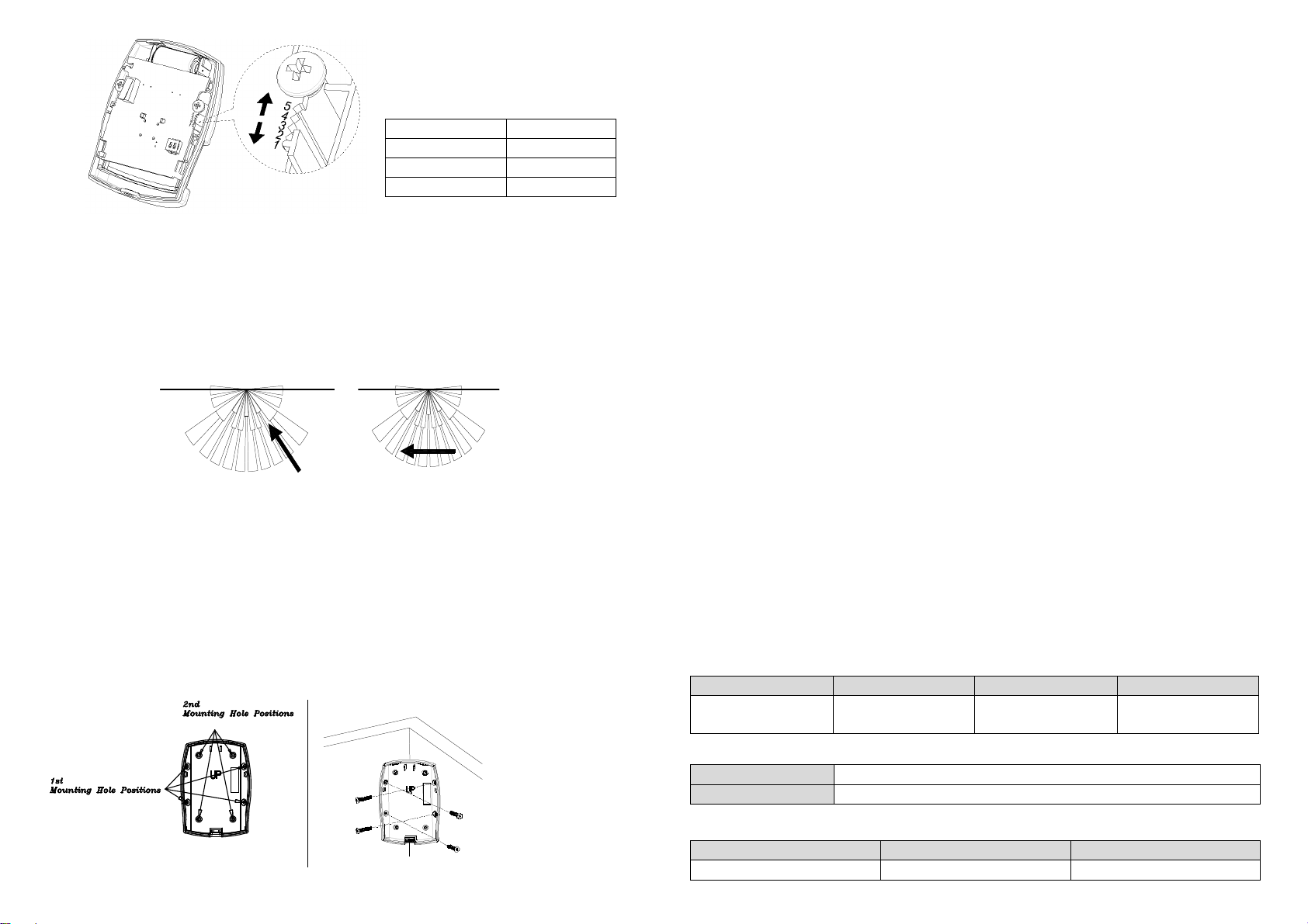
FIGURE 4a
FIGURE 4b
Slave Sleeping report
Z-
Wave Plus node
Sensor Notification
Security)
Sensor Notification
Security)
PCB Position Range
1 3m
3 6m
5 9m
When considering and deciding upon the mounting position for the detector the following points should
be considered to ensure trouble free operation:
1. Do not locate the detector facing a window or where it is exposed to or facing direct sunlight. PIR
Detectors are not suitable for use in conservatories.
2. Do not locate the detector where it is exposed to ventilators.
3. Do not locate the detector directly above a heat source, (e.g. fire, radiator, boiler, etc).
4. Where possible, mount the detector in the corner of the room so that the logical path of an intruder
would cut across the fan detection pattern. PIR detectors respond more effectively to movement
across the device than to movement directly towards it. (FIGURE 3)
FIGURE 2
5. Do not locate the detector in a position where it is subject to excessive vibration.
6. Ensure that the position selected for the PIR detector is within effective range of the system, (refer
to System Installation and Operating Manual).
Note: When the system is armed, household pets should not be allowed into an area protected by a
PIR detector as their movement would trigger the PIR and generate an alarm.
Less Sensitive More Sensitive
FIGURE 3
Installation
1. Carefully drill out the required mounting holes in the rear cover using 3mm drill according to whether
the unit is being mounted in a corner or against a flat wall.
Note: Using 1st mounting hole to fulfill corner mounting installation, while 2nd mounting hole for flat
wall installation. (FIGURE 4a & 4b)
Corner mounting
3. Using the rear cover as a template, mark the positions of the fixing holes on the wall.
4. Fix the rear cover to the wall using the two 18mm No.4 screws and 25mm wall plugs, (a 5mm hole
will be required for the wall plugs). Do not over-tighten the fixing screws as this may distort or
damage the cover.
5. Configure the detector as described below. Remember that on initial installation that the device
needs to be tested.
6. Check that the detector PCB is located and set in the correct position to provide the required
detection range. To adjust the PCB position, simply slide it up or down ensuring that the location
legs are aligned with the required position number marked on the board.
7. To refit the detector to the rear cover and locate the clips in the top edge into the rear cover. Push
the lower edge of the detector into place and refit the fixing screw in the bottom edge of the detector
to secure in position. Do not over-tighten the fixing screws as this may damage the casing.
8. By walking into a protected area within coverage of 110 degrees, the detector will now be triggered
each time the detector senses movement. The associated appliances will be activated. For
example, siren will be sounded or indication of movement detection will be shown on the controller.
It implies that the unit is working properly.
Programming
Z-Wave Group
The detector supports either one of two Z-wave Association Groups:
Group 1: Association with 1 Controller node.
Group 2: Association with 4 nodes (i.e. end devices such as smart plugs and other lighting controllers).
This allows the detector to transfer commands directly to end devices without the participation of the
controller. This has the effect that when the detector triggers, all devices associated with detector will be
operated.
Group 1 commands:
When the unit is powered up and was already a part of a Z-Wave network, the unit will send a
Notification Report to the node in Group 1.
When the detector senses a movement, the unit will send a Notification Report to the nodes of Group
1. Once the movement is stopped, a Notification Report will be sent again to Group 1.
Upon detector status being changed, the unit will check its battery status simultaneously. When the
battery level of the unit drops to an unacceptable level, the unit will emit Battery report to the nodes of
Group 1.
When performing Factory Reset the unit will send Device Reset Locally Notification to the node of
Group1.
Group 2 commands:
When the detector is triggered, the unit will send BASIC_SET command which contains a value to
the nodes of Group 2.
Z-Wave Plus Info
Role Type Node Type Installer Icon User Icon
Device Type (Home
Device Type (Home
Version
Protocol Library 3 (Slave_Enhance_232_Library)
Protocol Version 4.3D ( 6.71.01)
Manufacturer
Manufacturer ID Product Type Product ID
0x0060 0x0001 0x0006
 Loading...