

SP814 MOTION DETECTOR
The Motion Detector is a Z-Wave
any Z-Wave
Z-Wave
TM
TM
enabled network. Z-WaveTM enabled devices displaying the
logo can also be used with it regardless of the manufacturer, and ours
can also be used in other manufacturer’s Z-Wave
Motion Detector can control our modules via controller setting. Inclusion of this
Motion Detector on other manufacturer’s Wireless Controller menu allows
remote turn-on of connected modules and their connected lighting when the
detector is triggered. Z-Wave
they support that function.
The Motion Detector is designed with two detecting sensors, Passive Infra-Red
(PIR) sensor and light sensor, in order to fulfill the purpose of security and home
automation. When the detector is cooperated with security appliances, it is
acting as a security device by detecting changes in infra-red radiation levels. If
a person moves within or across the device field of vision, a trigger radio signal
will be transmitted to cause full alarm condition in order to frighten intruders away.
Alternatively, when the detector is worked with home automation appliances, the
detector can be set to perform the role of home automation device by detecting
both changes in infra-red radiation levels and percentage of lux levels. Once
night falls, the percentage of ambient illumination is lower than preset value. If
a person moves within or across the device field of vision, a trigger radio signal
will be transmitted so as to turn on the connected lightings for better illumination.
Two mounting methods are provided for varying detection range. The detector
can be mounted on a wall for farther detecting distance but narrower coverage;
while for ceiling mounting, shorter detecting distance can be made but desired
coverage can be expected at user’s disposal.
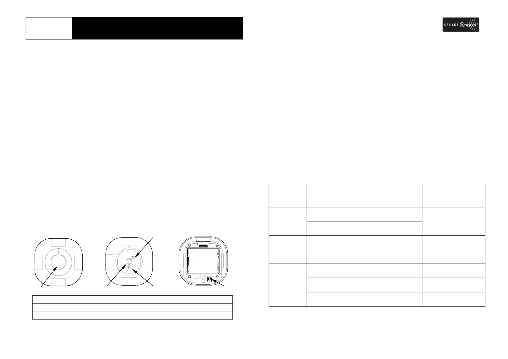
Product Overview
Front View
1
1 Lens Cover (wall-lens cover and ceiling-lens cover)
2 Photocell Sensor 4 Two-Color Indication LED (red & green)
3 PIR Sensor 5 Learning Key
TM
enabled device which is fully compatible with
TM
enabled networks. This
TM
nodes in the system also act as repeaters if
2
3
Inside View
4
RearView
5
Adding to Z-WaveTM Network
In the rear casing, there is a learning key which is used to carry out inclusion,
exclusion or association. Put a Z-Wave
inclusion/exclusion/association mode, and press the learning key on the
detector 3 times within 1.5 seconds, the detector beep s whenever y ou press the
learning key.
Auto Inclusion
Besides carrying out the inclusion procedure by pressing the learning key, the
detector executes the function of auto inclusion when…
1. The power is first supplied where no ID code has been stored in the detector .
The orange LED flashes on and off alternatively and repeatedly at 2-second
intervals.
2. The execution of exclusion/reset is successful where the stored ID code(s) is
(are) cleared.
Note: The node information of explorer frame will be emitted once every 5
seconds during 4 minutes auto inclusion until the inclusion process is complete.
The detector cannot execute detecting function if no ID code has been stored in
it.
Refer to the following table for functions indication and operation:
Function Description Indication
No node ID The Z-Wave Controller does not allocate a
node ID to the unit.
Inclusion 1. Have Z-Wave Controller entered
inclusion mode.
2. Pressing learning key 3 times within 1.5
seconds will enter inclusion mode.
Exclusion 1. Have Z-Wave Controller entered
exclusion mode.
2. Pressing learning key 3 times within 1.5
seconds will enter exclusion mode.
Reset 1. Press learning key 3 times within 1.5
seconds.
2. Within 1 second, press and hold learning
key for 5 seconds until LED is OFF.
3. IDs are cleared and all settings will be
reset to factory default.
1
TM
Wireless Controller into
2-second on, 2-second
off
One short beep when
learning key is pressed
One short beep when
learning key is pressed
One short beep when
learning key is pressed
One long beep for 5
seconds
2-second on, 2-second
off (for 4 minutes)
Association 1. Have Z-Wave Controller entered
association mode.
2. Pressing learning key 3 times within 1.5
seconds will enter association operation.
3. There are two groupings – 1 and 2. See
the following section for more info.
One short beep when
learning key is pressed
Including a node ID allocated by Z-Wave Controller means inclusion. Excluding a
node ID allocated by Z-Wave Controller means exclusion.
Failed or successful results in including/excluding the node ID can be viewed from the
Z-Wave Controller.
When “Exclusion” is completed, the parameter 1 of configuration will be restored to
default value, while other parameters will retain their settings before exclusion.
Note: The Motion Detector will stay “awake” for ten minutes when power is first
supplied to allow time for configuration.
(I) Grouping 1 (max. 1 node)
If the device (e.g. Z-Wave controller) is associated into detector’s Grouping 1,
the associated device will receive report commands from the detector when
event occurs. Three types of reports can be emitted by the detector, they are:
Event Type Report Type
Power Up
PIR Trigger
PIR Status
Low Battery Status
On
PIR Trigger
Off
(II) Grouping 2 (max. 3 nodes)
If a device (e.g. On/Off Module) is associated into the detector’s Grouping 2, the
device will receive Basic Set Command from the detector if PIR sensor/light
sensor of the detector has been triggered.
BASIC_SET (Value = 0 or 1-99), where
Value = 0 (indicates “Off”)
Value = 1-99, 0xFF (indicates “On” for binary switch, e.g. On/Off Module or
“Dim Level” for multilevel switch device, e.g. Lamp Module)
ALARM_REPORT
(Alarm Type = 02, Alarm Level = 0x01)
BINARY SENSOR REPORT
(Sensor Value = 0xFF)
BINARY SENSOR REPORT
(Sensor Value = 0x00)
ALARM_REPORT
(Alarm Type = 01, Alarm Level = 0xFF)
Note: For more information on how to configure the Basic Set Command,
please refer to the section of Basic Set Level on page 4.
Reset
To reset the device, simply press the learning key on the detector 3 times within
1.5 seconds, and then press and hold the learning key within 4 seconds until
beep sound stops. Home ID and node ID stored in the detector will be cleared
and the detector will be restored to factory default.
Choosing a Mounting Location
The Motion Detector can be mounted either on a wall or under a ceiling. Before
selecting a position for Motion Detector, the following points should be noted:
1. Do not position the detector facing a window/fan/air-conditioner or direct
sunlight.
2. Do not position the detector directly above or facing any source of heat, e.g.
fires, radiators, boiler etc.
3. Ensure the detector is positioned in place where the li ght source de tected by
the detector is consistent with actual ambient illumination. Do not locate
the detector in a shadowy place.
4. Where possible, mount the detector so that the logical path of an intruder
would cut across the fan pattern rather than directly towards the detector
(FIGURE 1).
FIGURE 1
5. For best results, locate the detector directly facing an entrance.
Installation
1. Undo and remove the screw from the bottom edge of the detector to detach
the rear cover (FIGURE 2).
2. Unscrew the screw from the battery cover and remove the battery cover.
2
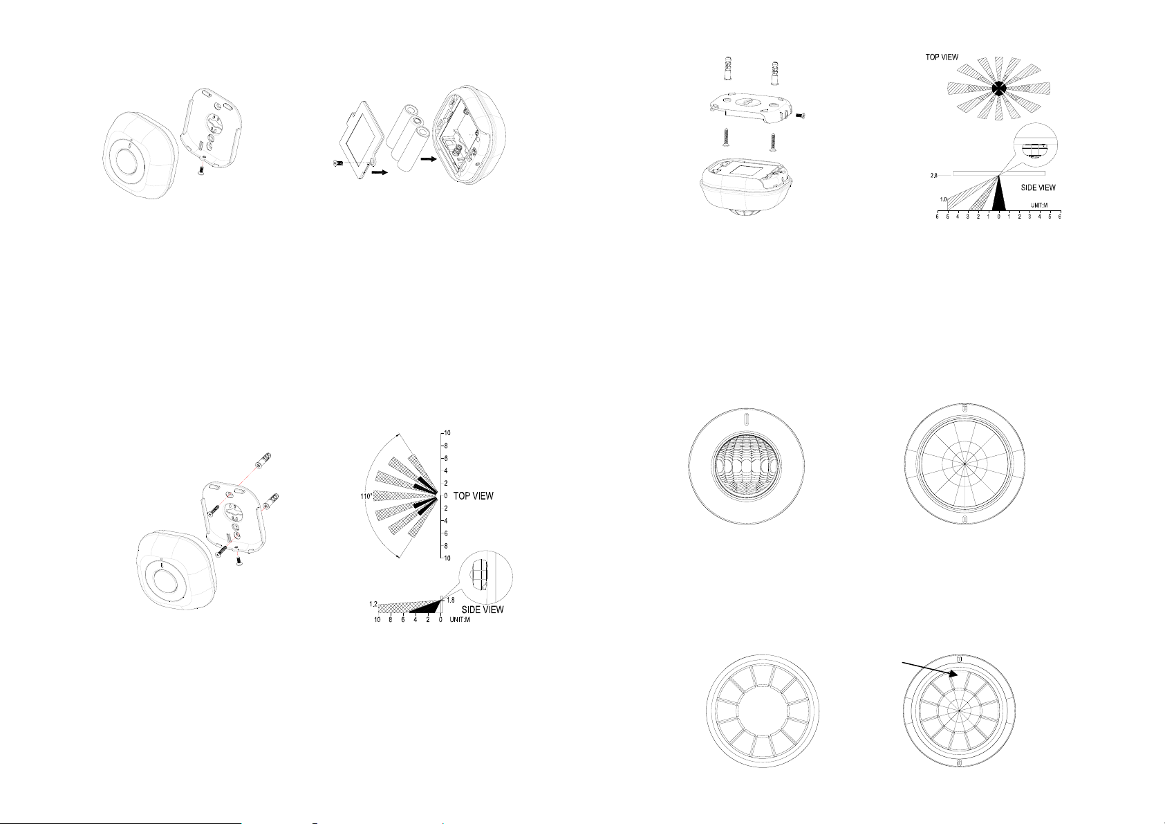
3. Insert 3 AA-size 1.5V alkaline batteries to the battery compartment, ensuring
correct polarity is put (FIGURE 3).
FIGURE 2 FIGURE 3
4. Two ways of mounting are applicable to the detector. Decide the detector
is to be wall-mounted (FIGURE 4a) or ceiling-mounted (FIGURE 5a) based
on the coverage angles shown in FIGURE 4b and FIGURE 5b. Hold the
rear cover in position and mark the two mounting holes. Drill the holes,
insert the plastic wall plugs and screw the rear cover to the wall or ceiling
using the screws supplied.
5. Engage the detector to the rear cover firmly.
(I) Wall Mounting
The recommended position for wall mounting is at the height of 1.8m (5.91 f t )
from the floor. At this height, the optimum detection range is up to 10m
(32.81 ft) with coverage range of 110 degrees (FIGURE 4b).
FIGURE 4a
FIGURE 4b
(II) Ceiling Mounting
The recommended position for ceiling mounting is at the height of 2.8m
(9.19ft) from the floor. At this height, the optimum detection range is up to
5m (16.41ft) with coverage range of 360 degrees (FIGURE 5b).
FIGURE 5a FIGURE 5b
Settings
Coverage Range Adjustm ents
Two types of lens covers are provided for the detector. Wall-lens cover
(FIGURE 6a) is to be used when the detector is wall-mounted, whereas
ceiling-lens cover (FIGURE 6b) is to be used when the detector is
ceiling-mounted. The coverage range adjustment is only applicable to
ceiling-lens cover; choose correct lens cover before mounting.
FIGURE 6a FIGURE 6b
The shading cap is composed of 12 segments for limiting the detection coverage,
and each segment covers detection angle of 30 degrees (FIGURE 6c). Follow
the grooves on the cap, cut the cap to a suitable size and place it onto the
ceiling-lens cover (FIGURE 6d). The remaining segments are used for
blanking off an undesirable detection area.
3
One segment
is removed
FIGURE 6c
FIGURE 6d

Simply turn the cover anticlockwise to remove the wall-lens cover from the
detector (FIGURE 6e).
Once the wall-lens covers is removed, reload the detector with ceiling-lens cove r
and turn it clockwise, ensure the mark on the cover is pointing towards and
aligned with the mark on the detector (FIGURE 6f).
Note: To detect movements with detection coverage up to 360 degrees, simply
reload the ceiling-lens cover without shading cap. No movements can be
detected if the detector is reloaded with a shading cap which maintains 12 lens
segments.
Warm-Up
It will take approximately 2 minutes to warm up after battery has b een connected.
During this period, the detector beeps once every 3 seconds. When a long
beep is sounded with red LED turns on steadily for 5 seconds, it implies warm-up
procedure is completed and the detector is ready for detection.
FIGURE 6e
FIGURE 6f
Operation
(I) General Operation
Mounting location is a critical factor for deciding the type of lens to be used for
the detector. Please decide whether the detector is going to be wall-mounted
or ceiling-mounted before the operation procedure is carried on.
Wall Mounting
1. Place the wall-lens cover onto the detector.
2. By walking into a protected area within coverage of 110 degrees, the
detector will now be triggered each time the detector senses movement. The
orange LED on the detector will be illuminated and the associated
appliances will be activated. For example, siren will be sounded or
indication of movement detection will be shown on the controller. It implies
that the unit is working properly.
Ceiling Mounting
1. Place the ceiling-lens cover (shading cap free) onto the detector.
2. By walking into a protected area within coverage of 360 degrees, the
detector will now be triggered each time the detector senses movement.
The orange LED on the detector will be illuminated and the associated
appliances will be activated. For example, the siren will be sounded or
indication of movement detection will be shown on the controller. It implies
that the unit is working properly.
3. Place the shading cap onto the ceiling-lens cover.
4. Check whether same results can be gained by walking into a protected area
within coverage that is at your disposal.
(II) Configuration of Z-Wave Command
The following information is for someone that has some experience in setting up
a Z-Wave or someone that has computer software running a Z-Wave controller.
Please get familiar with software of Z-Wave controller before getting started.
Basic Set Level
If PIR/light sensor of the detector has been triggered, the detector will send a
Basic Set Command to the associated devices. For instance, the ambient
illumination falls below a set detecting percentage of lux level, the detector
sends a Basic Set Command to a Lamp Module and the Lamp Module turns on
with 70% of brightness after receiving the commend. To adjust the value of
Basic Set, please configure with the following value:
Parameter number: 1
Size: 1
Value: 0 (indicating “Off”)
1-99, 0xFF (indicating “On” for binary switch, e.g. On/Off Module
or Indicating “Dim Level” for multilevel switch device,
e.g. Lamp Module)
4

Note: The default value is 99, which implies that the associated device will turn
on (or illuminate with highest brightness) after receiving the command.
Enabling/Disabling Sensor Detecting Function
There might be times when users wish to suspend the detecting functions of the
detector temporarily. To enable or disable PIR sensor and light sensor, please
configure with the following value:
Parameter number: 2
Size: 1
Value: 0 (sensor disabled)
1 (sensor enabled)
Note: The default value is set in 1, which implies that the sensor detecting
function is on. Reconnection of power supply will enable the sensor detecting
function automatically.
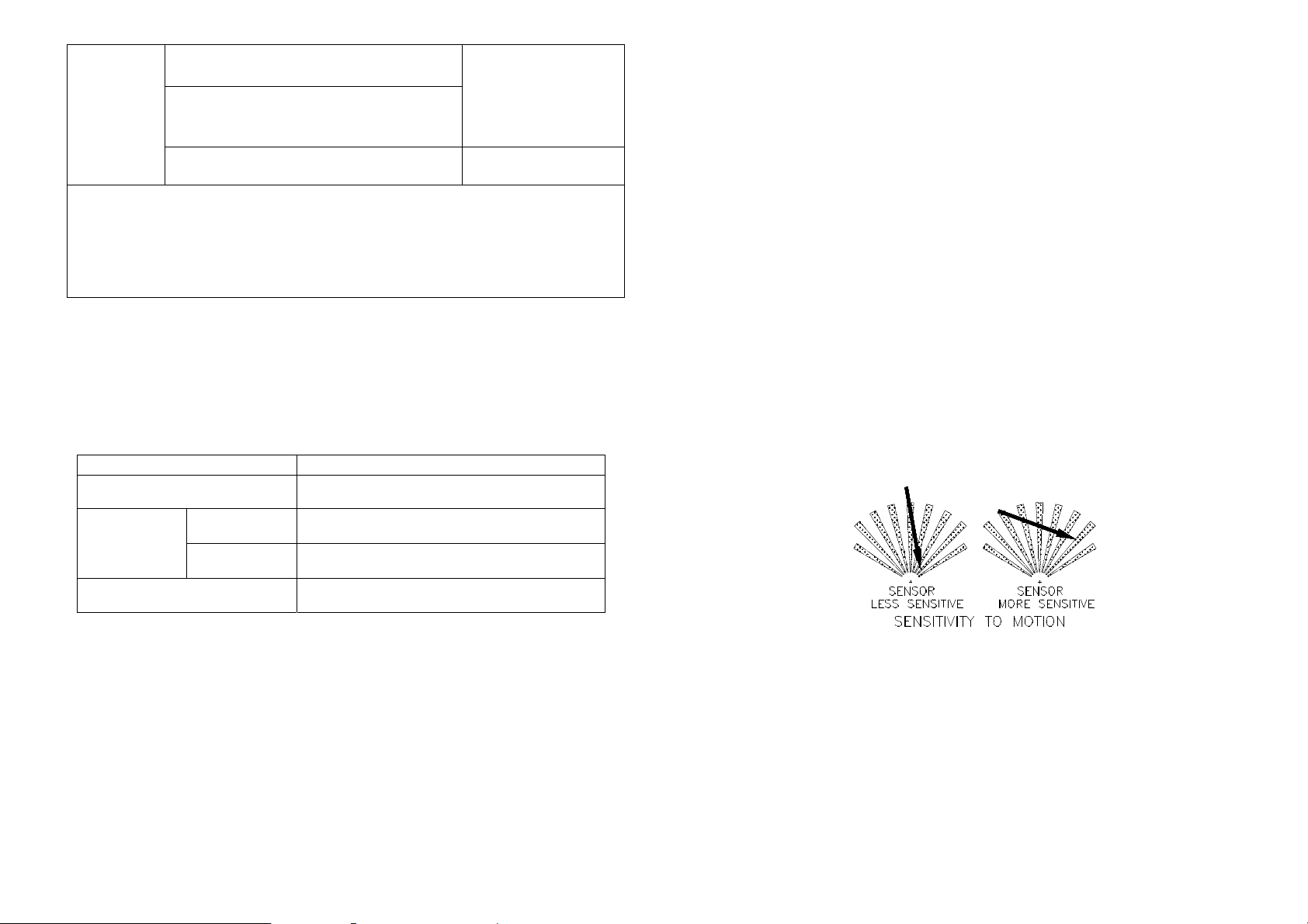
Sensitivity Level (PIR sensor only)
In order to provide a best efficiency of the detector, it is recommended to test the
detector with movements from a farthest end of the coverage area at first time of
use. If movements cannot be detected sensitively, simply adjust the sensitivity
level. The sensitivity level is between 1 to 10. To adjust sensitivity level of the
detector, please configu re with the following value:
Parameter number: 3
Size: 1
Value (range): 1 ~ 10 (the larger the number, the higher the sensitivity)
Note: The default value is set in 6, which implies medium sensitivit y.
Re-trigger Interval Setting (PIR sensor only)
This function is designed for setting the interval which allows PIR sensor to be
re-triggered after the detector has been triggered. For example, the interval is
set in 20 seconds. If a movement is detected, only wait after 20 seconds the
detector can be triggered again if it detects another movement. During 20
seconds period, the detector will not detect (FIGURE 7). The time interval can
be set between 5 seconds to 3600 seconds. To adjust time interval, please
configure with the following value:
Parameter number: 4
Size: 1
2 (if value is set larger than 127)
Value (range): 5 (sec) ~ 3600 (sec)
triggered
20 seconds
triggered
detected a
detected a
movement
movement
(no response)
detected a
movement
FIGURE 7
Note: The default value is set in 5, which implies that the detector can only be
re-triggered after 5 seconds of interval. The orange LED is on for one second
when the detector detects a trigger.
On-Off Duration Setting
The function of on-off duration setting will be useful if the detector is connected
with a module or lighting. The duration determines how long the detector
should wait to send a Basic Set Command (Value = 0) to the associated device
after sending a Basic Set Command (Value = Basic Set Level). For instance, a
movement has been detected, the detector sends a Basic Set Command (Value
= Basic Set Level) to a Lamp Module and the Lamp Module turns ON. After
100 seconds (the user can set the time between 5 to 3600 seconds), the Lamp
Module turns off after receiving OFF command (i.e. Basic Set Command (Value
= 0)). To adjust the on-off duration, please configure with the following value:
Parameter number: 6
Size: 1
2 (if value is set larger than 127)
Value (range): 5 (sec) ~ 3600 (sec)
detector is
triggered
light
turns on
light
turns off
5 seconds
detected a
movement
FIGURE 8
Note: The default value is set in 15, which implies that the detector will send an
OFF command to associated appliances 15 seconds after they’ve been
triggered. The green LED will stay on for 1 second after 15 seconds of interval.
Lux Level Setting
The user can set a detecting percentage of lux level which determines when the
5

light sensor will be activated. If percentage of lux level of ambient illumination
falls below this percentage, and a person moves across or within the protected
area, the detector will emit Z-Wave ON Command (i.e. Basic Set Command
(Value = Basic Set Level)) to controller and activate connected modules and
lighting. Percentage can be set between 1% to 100%. To adjust percentage
of lux level, please configure with the following value:
Parameter number: 5
Size: 1
Value (range): 1 (%) ~ 100 (%)
Note: The default value is set in 10, which implies 10% of lux level.
Advanced Operation
Low Battery Indication
When the battery level of the detector drops to a certain level, the detector will
emit a low battery command to the node of Grouping 1; meanwhile, the detector
will flash red LED once every 30 seconds. When this occurs, please replace
the batteries as soon as possible.
The users can also enquire the battery status of the detector by sending a
Battery Get Command via controller. Once the detector receives the command,
it will return a Battery Report Command [Command Class Battery, Battery
Report, Battery Level = 20%-100%] to the controller. If it displays with a
message of “Battery Level = 0xFF (255)”, it implies that the detector is at low
battery status.
Wakeup Command Class
The detector stays in sleep status for the majority of time in order to conserve
battery life. However, it can be woken up by either triggers of movement or set
time.
The unit stays in sleep stat us for the majority of time in order to conserve battery
power. However, it can be woken up at specified intervals by setting
WAKE_UP_INTERVAL_SET command by Z-Wave Controller. After the unit
wakes up, it will send Wakeup Notification Command to the node ID that
requires to be reported. The minimum and maximum wakeup interval is 60
seconds and 194 days respectively. Allowable interval among each wakeup
interval is 1 second, such as 60, 61, 62 ….
Note: The default value is 1 hour, which implies that the detector awakes and
sends the Wakeup Notification Comman d to the set node every hour.
Command Classes
The Motion Detector supports Command Classes including…
* COMMAND_CLASS_ALARM * COMMAND_CLASS_BASIC
* COMMAND_CLASS_BATTERY * COMMAND_CLASS_VERISON
* COMMAND_CLASS_ASSOCIATION_V2 * COMMAND_CLASS_CONFIGURATION
* COMMAND_CLASS_SENSOR_BINARY * COMMAND_CLASS_WAKE_UP_V2
* COMMAND_CLASS_MANUFACTURER_SPECIFIC
Troubleshooting
Symptom Possible Cause Recommendation
LED cannot be displayed Run out of battery power Replace a new battery
Check if reverse battery polarity Refit the battery with correct
polarity
The detector not working Check if mounting location is
Two minutes warm up is
completed, but cannot hear long
beep sound (LED flashes on &
off repeatedly at 2-second
intervals)
The detector does not stay
awake for 10 minutes when
power is first supplied
proper
Check if the detector is out of
order
Check if detector is first power
up or the detector has executed
exclusion or reset procedure
Check if detector is out of order Remove the batteries, press
Reposition its mounting location
Remove the source of
interference
Do not open the detector; send it
to the local retailer.
Please carry out inclusion
procedure; make sure there are
ID codes stored in the detector.
learning key several times to
release the existing battery power
and wait for 1 to 2 minutes before
replacing the batteries.
6

Specifications*
Battery 1.5V AA size x 3
Battery Life 2 years**
Operating Range Up to 30 meters line of sight (indoor)
Warm Up Time About 2 minutes
PIR Detection Coverage Wall-Mounted:
Operating Frequency 908.42 MHz
*Specifications are subject to change without notice
**15 triggers per day
Up to 10m x 110° (at 1.8m mounting height & 25°C)
Ceiling-Mounted:
Up to 5m x 360° (at 2.8m mounting height & 25°C)
2013/10
Federal Communication Commission Interference St atement
This equipment has been tested and found to comply with the limits for a Class B digital
device, pursuant to Part 15 of the FCC Rules. These limits are designed to provide
reasonable protection against harmful interference in a residential installation. This
equipment generates, uses and can radiate radio frequency energy and, if not installed
and used in accordance with the instructions, may cause harmful interference to radio
communications. However, there is no guarantee that interference will not occur in a
particular installation. If this equipment does cause harmful interference to radio or
television reception, which can be determined by turning the equipment off and on, the
user is encouraged to try to correct the interference by one of the following measures:
- Reorient or relocate the receiving antenna.
- Increase the separation between the equipment and receiver.
- Connect the equipment into an outlet on a circuit different from that to which the
receiver is connected.
- Consult the dealer or an experienced radio/TV technician for help.
This device complies with Part 15 of the FCC Rules. Operation is subject to the follo wing
two conditions: (1) This device may not cause harmful interference, a nd (2) this device
must accept any interference received, including interference that may cause undesire d
operation.
FCC Caution: Any changes or modifications not expressly approved by the party
responsible for compliance could void the user's authority to operate this e quipment.
This transmitter must not be co-lo cated or ope rating in conjuncti on with any other ante nna
or transmitter.
WARNING:
Do not dispose of electrical appliances as unsorted municipal waste, use separate collection
facilities.
Contact your local government for information regarding the collection systems available.
If electrical appliances are disposed of in landfills or dumps, hazardous substances can leak into the
groundwater and get into the food chain, damaging your health and well-being.
When replacing old appliances with new ones, the retailer is legally obligated to take back your old
appliance for disposal at least for free of charge.
7
 Loading...