


SM810
DOOR/WINDOW DETECTOR
FIXED
W
The Door/Window Detector is a Z-Wave PlusTM enabled device and is fully compatible with any Z-WaveTM
enabled network. The device can be set up in a Z-wave network to communicate directly with other end
devices such as lighting controllers, or to report directly to a Z-wave controller (usually a gateway).
Z-WaveTM enabled devices displaying the Z-WaveTM logo can also be used with it regardless of the
manufacturer, and ours can also be used in other manufacturer’s Z-WaveTM enabled networks.
Inclusion of this Door/Window Detector on other manufacturer’s Wireless Controller menu allows remote
turn-on of connected modules and their connected lighting when the Detector is triggered.
Product Overview
Detector Magnet
LED
BATTERY
TAMPER
SWITCH
BATTERY
MYLAR
SCRE
Adding to Z-Wave Network
Auto Inclusion
The detector supports Auto Inclusion feature where it will automatically enter Inclusion mode when first
powered up after a factory reset.
1. In the front casing, there is a tamper switch which is used to carry out inclusion, exclusion or reset.
2. Put a Z-Wave Controller into inclusion mode.
3. Insert 2 CR2032 batteries to the battery compartment with the correct polarity. The LED on the
device will turns on.
Battery Cover
CR2450
Battery
Battery Cover
45°
4. The Inclusion process should be completed when the LED turns off.
Note: If Auto Inclusion fails, refer to the Troubleshooting section regarding Manual Inclusion.
Testing
1. Remove the battery cover with the tamper switch not being pressed on the detector (test mode),
detach or close the magnet from the Detector, the LED on the detector will illuminate.
2. After proper installation and test, put the battery cover back to the detector and the detector enters
the normal mode.
Note: After removing batteries, wait for 5 seconds to refit batteries.
Mounting the Detector
Choosing the location
The Door/Window Detector is suitable for mounting in dry interior locations only.
Decide which doors/windows are to be protected by Door/Window Detectors, (usually the front and back
doors as a minimum will have Door/Window Detectors fitted). Additional detectors may also be fitted
where required to other vulnerable doors or windows, (e.g. garage, patio/conservatory doors etc).
Note: Take care when fixing the Detector to a metal frame, or mounting within 1m of metalwork (i.e.
radiators, water pipes, etc) as this could affect the radio range of the device. If required, it may be
necessary to space the magnet and detector away from the metal surface using a plastic or wooden
spacer to achieve the necessary radio range.
Installation
1. Use the adhesive tape to fit detector on the door or window.
2. Fit the magnet to the moving part of the door/window opposite the detector using the adhesive tape.
3. Ensure that the parallel gap between the magnet and detector is less than 20mm and that the
matching line on the magnet is pointing towards and aligned with the line on the detector. An alarm
condition will be occurred if the gap is greater than 35mm.
Operation
1. If first use of SM810 with no node ID, LED will turns ON for 30 sec. when first power on the device
to lead the user for auto inclusion. After Inclusion is completed, the device will stay awake for 25
sec. for set up by user from the controller. After 25 sec., the unit will enter sleeping mode, if set up
is still needed, the user can press tamper switch for SM810 to be awake for another setting.
2. Due to limited power from CR2450, the unit may not continuously operate for a long time due to
power consumption. Therefore, set up time for SM810 should be minimized, and repeatedly
press of Tamper should be avoided as well, in order to prevent unusual incident by a quick battery
voltage drop down.
3. User can enter test mode by releasing the Tamper switch; in the meantime if magnetic sensor is
triggered then the LED will be illuminated. User can confirm whether the Tamper switch has been
pressed properly by implementing this function. When Tamper switch is to be pressed and enter
normal mode, LED will not be illuminated even if the magnetic sensor is triggered, unless low
battery is detected.
4. When the tamper switch is pressed, the unit enters normal mode and the red indicator LED on the
Detector will not illuminate to conserve battery life when the detector is triggered, (unless the battery
power is low).
Programming
Slave Sleeping report
Z-
Wave Plus node
Sensor Notification
Control
)
Sensor Notification
Control
)
Event
Length
The power is applied for the first time
0x08 0x01 null
The battery is Low
0x08
0x0A
null
Door/Window detector t
rigger
OPEN
0x06 0x16 null
Door/Window
detector t
rigger
Close
0x06 0x17 null
Tamper switch being press more than 10
0x07 0x03 null
Tamper switch being press
0x07 0x00
null
Minimum Wake Up Interval
600s
(10
minutes
)
Maximum Wake Up Interval
86400
s
(1
day)
Default Wake Up Interval
14400
s
(4
hours)
Wake Up Interval Step Seconds
600s (10 minutes
)
2-second on, 2
-
second
For 2
minutes
Z-Wave Group
The detector supports either one of two Z-wave Association Groups:
Group 1: Association with 1 Controller node.
Group 2: Association with 4 nodes (i.e. end devices such as smart plugs and other lighting controllers).
This allows the detector to transfer commands directly to end devices without the participation of the
controller. This has the effect that when the detector triggers, all devices associated with detector will be
operated.
Group 1 commands:
When the unit is powered up and was already a part of a Z-Wave network, the unit will send a
Notification Report to the node of Group 1.
When the tamper switch is released, the unit will send ALARM REPORT command to the nodes of
Group 1.
Upon detector status being changed, the unit will check its battery status simultaneously. When the
battery level of the unit drops to an unacceptable level, the unit will emit Battery report to the nodes of
Group 1.
When performing Factory Reset the unit will send Device Reset Locally Notification to the node of
Group1.
Group 2 commands:
When the door/window is opened, the unit will send BASIC_SET command which contains a value to
the nodes of Group 2.
When the door/window is closed, the BASIC_SET command will also be sent to the nodes of Group
2.
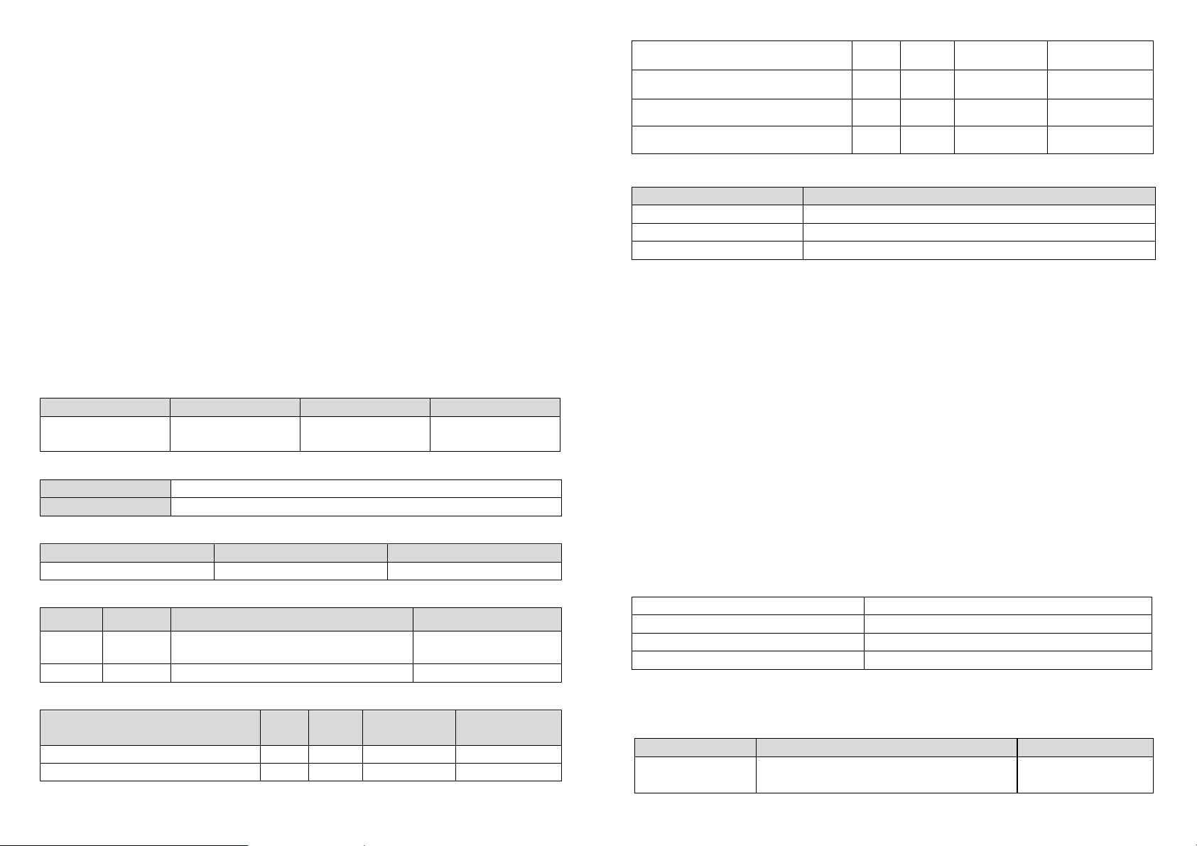
Z-Wave Plus Info
Role Type Node Type Installer Icon User Icon
Device Type (Access
Version
Protocol Library 3 (Slave_Enhance_232_Library)
Protocol Version 4.6 ( 6.71.00)
Manufacturer
Manufacturer ID Product Type Product ID
0x0060 0x0002 0x0003
AGI (Association Group Information) Table
Group Profile Command Class & Command (List) N bytes Group Name(UTF-8)
1 General
2 Control Basic Set Basic Set
Notification Report
Device Reset Locally Notification
Notification
Event Type Event
Parameters
Device Type (Access
Lifeline
Event Parameters
seconds and released
Battery
Battery Report (value) Description
0x64 Battery is high
0x10 Battery is normal
0x00 Battery is low
Command Classes
The module supports Command Classes including…
COMMAND_CLASS_ZWAVEPLUS_INFO_V2
COMMAND_CLASS_ASSOCIATION_V2*
COMMAND_CLASS_ASSOCIATION_GRP_INFO*
COMMAND_CLASS_TRANSPORT_SERVICE_V2
COMMAND_CLASS_VERSION_V2*
COMMAND_CLASS_MANUFACTURER_SPECIFIC_V2*
COMMAND_CLASS_DEVICE_RESET_LOCALLY*
COMMAND_CLASS_POWERLEVEL*
COMMAND_CLASS_BATTERY *
COMMAND_CLASS_SECURITY
COMMAND_CLASS_SECURITY_2
COMMAND_CLASS_NOTIFICATION_V8*
COMMAND_CLASS_WAKE_UP_V2*
COMMAND_CLASS_FIRMWARE_UPDATE_MD_V4*
*Items marked an asterisk are secure command classes.
Wakeup Command Class
After it has been included into a Z-wave network, the detector will go to sleep but will send a Wakeup
Notification Command periodically at preset period to the controller. The detector will stay awake for 10
seconds at least and then go back to sleep to conserve battery life.
The time interval between Wakeup Notification Commands can be set in the Wakeup Command Class
based on the range values below:
Troubleshooting
The table below lists the several steps involved when adding or removing the detector from the Z-wave
network.
Action/Status Description LED indication
No node ID
The Z-Wave Controller does not allocate a node
ID to the unit.
off
 Loading...