

WIRELESS KEYPAD SA801
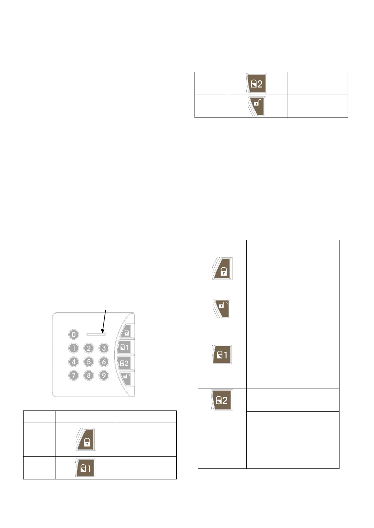
Setting/low battery LED
Installation and Operating Instructions
FCC ID: FU5SA801
These instructions should be read in conjunction
with your System Installation and Operating
Manual and be retained for future reference.
Introduction
This Wireless Keypad is suitable for use with a series
of Everspring Wireless Intruder Alarm Systems,
operating at 868MHz and 923MHz only.
The Wireless Keypad is used to control the system by
using a four digit Administrator password. The
Keypad incorporates a Panic and anti-tamper
protection features that will immediately initiate a Full
Alarm condition when activated. Any attempt to open
the casing of the Keypad will immediately initiate a full
alarm condition even if the system is disarmed,
(unless the system is in Service, Test or Programming
modes). In addition if a sequence of incorrect key is
pressed once, the LED of back light will flash. If a
sequence of incorrect key is pressed three times the
Keypad will be locked out for the next 30 seconds.
Subsequent lockout for three times, the Keypad will
emit tamper signal to the Control Panel.
3
4
The Keypad is powered by 3 x AA 1.5V alkaline
battery. Under normal operating conditions this will
provide an expected life in excess of 1 year. When
the battery level falls below an unacceptable level, the
“Setting/Low Battery” LED on the front of the Keypad
will flash 4 times when pressing the first key.
Subsequent key cannot be pressed until initial 4
flashings are completed. When this occurs the
batteries should be replaced as soon as possible.
Part-arm 2
Disarm
LED Indication
Keypad Status Indication
Success:
back light 0~9 extinguish
Failure:
Arm
Disarm
back light 0~9 flashing 3 times
Success:
back light 0~9 extinguish
Failure:
Sequence
1
2
Function Key Meaning of Key
Arm
Part-arm 1
Pressing any
key or function
key
1
Part-arm 1
Part-arm 2
back light 0~9 flashing 3 times
Success:
back light 0~9 extinguish
Failure:
back light 0~9 flashing 3 times
Success:
back light 0~9 extinguish
Failure:
back light 0~9 flashing 3 times
back light 0~9 will be on
+
Panic
Success:
back light 0~9 extinguish
Failure:
back light 0~9 flashing 3 times
ID Code learn
mode
Success:
back light 0~9 extinguish and
the LED of 4 function keys
illuminate once simultaneously
Failure:
back light 0~9 flashing 3 times
Alarm Memory
Success:
the LED of 4 function keys
flash once simultaneously
Failure:
back light 0~9 extinguish
Fig. 1 Fig. 2
2. Using the mounting plate as a template, mark the
positions of the two fixing holes on the wall.
3. Fix the mounting plate to the wall using the
screws and wall plugs provided. (Fig. 2) Do not
over-tighten the fixing screws as this may distort
or damage the mounting plate.
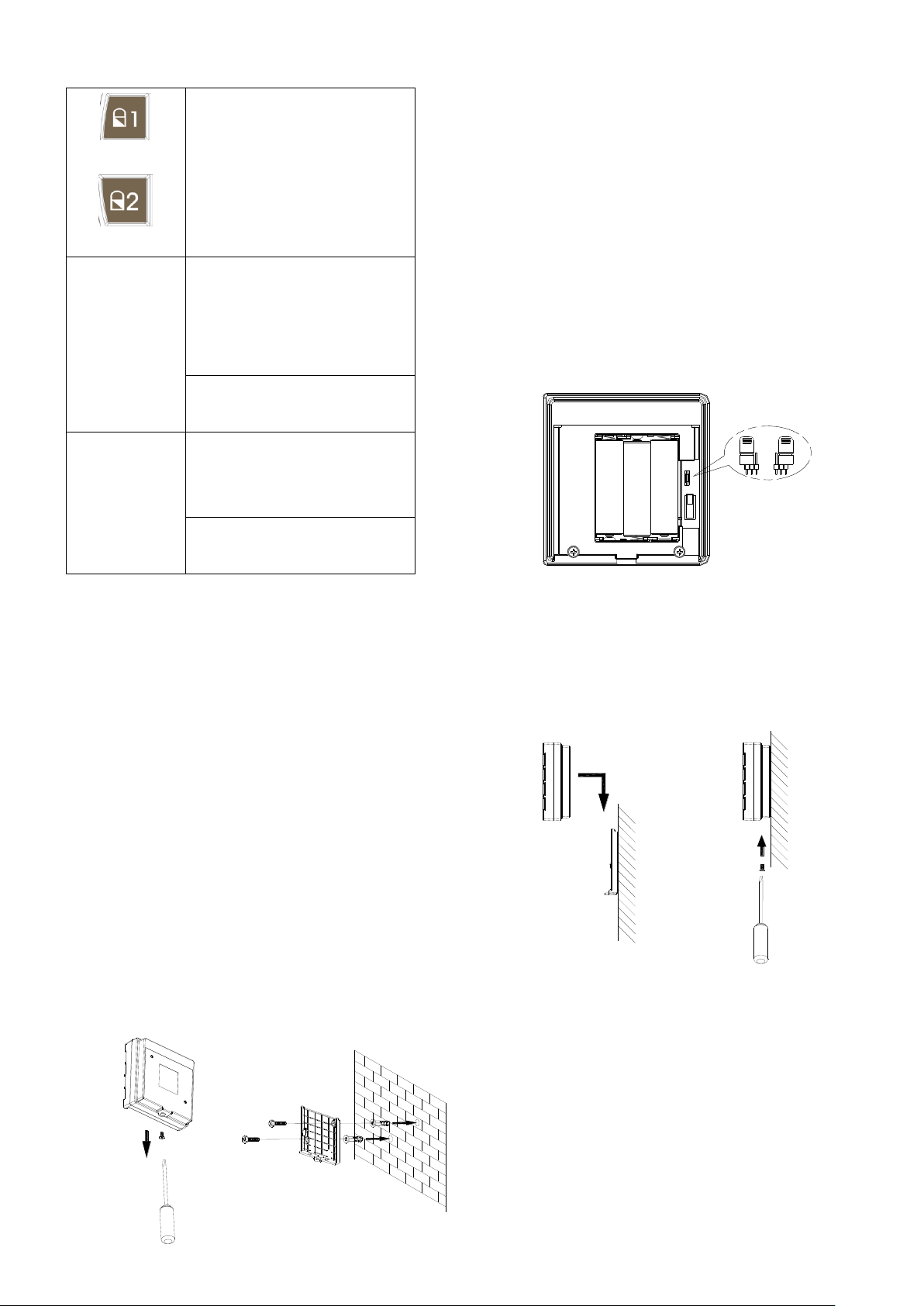
4. There is one jumper link located adjacent to the
battery compartment. (Fig. 3)
Jumper link J1: Reset to Factory default
Positioning the Keypad
The Keypad should be mounted in a position close to
the main entrance door so that the Administrator
password can be entered easily.
Ensure that the position selected for the Keypad is
within the effective range of the control panel.
Note: DO NOT fix the Keypad to metalwork or locate
the unit within 1m of metalwork (i.e. radiators, water
pipes, etc) as this could affect the radio range of the
Keypad.
Installing the Keypad
1. Undo and remove the fixing screw from the
bottom edge of the Keypad and remove the wall
mounting plate. (Fig. 1)
Fig. 3
5. Connect the 3 x AA alkaline batteries to the
battery compartment.
6. Click the Keypad to the mounting plate and screw
the fixing screw. (Fig. 4a & 4b) Do not
over-tighten the fixing screw.
Fig. 4a Fig. 4b
Note: The Keypad is supplied with a default
Administrator password of: 1234. For security
reasons, it is recommended that this password is
changed to another four digit number which only you
and other users of the system know.
Note: The Keypad has back light illumination facility.
The back light of digit 0~9 won’t be off until 5-second
2

illumination duration expires each time when you
press any key. Once transmission is successful the
back light of digit 0~9 will extinguish. Failure to input
any key more than 5 seconds after each pressing will
be treated as invalid input and the back light of digit
0~9 will extinguish.
Operating the Keypad
When using the Keypad the keys must be pressed
firmly and within five seconds of each other. If you
make a mistake, wait five seconds and recommence
operating from the beginning of the sequence.
Compatible with Control Panels of SC801,
SC811 and SC821
1. Arm the system:
code of the control panel.
(3) If the control panel is part-armed successfully, the
back light of digit 0~9 of the Wireless Keypad will
extinguish, whereas if failure, the back light of digit
0~9 will flash three times.
4. Disarm the system:
(1) Press key from the Wireless Keypad.
(2) Using the Wireless Keypad to press 4-digit access
code of the control panel.
(3) If the control panel is disarmed successfully, the
back light of digit 0~9 of the Wireless Keypad will
extinguish, whereas if failure, the back light of digit
0~9 will flash three times.
5. Alarm Memory
(1) Press key from the Wireless Keypad.
(2) Using the Wireless Keypad to press 4-digit access
code of the control panel.
(3) If the control panel is armed successfully, the back
light of digit 0~9 of the Wireless Keypad will
extinguish, whereas if failure, the back light of digit
0~9 will flash three times.
2. Part-arm 1:
(1) Press key from the Wireless Keypad.
(2) Using the Wireless Keypad to press 4-digit access
code of the control panel.
(3) If the control panel is part-armed successfully, the
back light of digit 0~9 of the Wireless Keypad will
extinguish, whereas if failure, the back light of digit
0~9 will flash three times.
3. Part-arm 2:
In order to verify if a full alarm condition has been
initiated while you are away, a LED indication for
alarm activation will be shown on the control panel.
When or after an alarm condition has been generated,
follow the steps in sequence as below:
(1) Press key on the Wireless Keypad.
(2) Using the Wireless Keypad to press 4-digit
access code of the control panel.
All four function keys –
on the Keypad
will illuminate shortly, which implies that the Wireless
Keypad received radio signal of alarm memory from
the control panel.
Compatible with Solar-Powered Control
(1) Press key from the Wireless Keypad.
(2) Using the Wireless Keypad to press 4-digit access
Panel (SE801)
1. Arm the system
3

(1) Press key from the Wireless Keypad.
5. Alarm Memory
When the Solar-powered control panel initiated a full
alarm condition, press the following keys after the
(2) Press 4-digit Administrator password of the
Wireless Keypad.
(3) If the control panel is armed successfully, the
back light of digit 0~9 of the Wireless Keypad will
extinguish, whereas if failure, the back light of
digit 0~9 will flash three times.
2. Part-arm 1
(1) Press key from the Wireless Keypad.
(2) Press 4-digit administrator password of the
Wireless Keypad.
(3) If the control panel is part-armed successfully, the
back light of digit 0~9 of the Wireless Keypad will
extinguish, whereas if failure, the back light of
digit 0~9 will flash three times.
elapse of alarm duration of the Solar-powered control
panel, so that the Wireless Keypad can receive radio
signal of alarm memory from the control panel.
Note: If the following keys have been pressed before
the alarm duration expires, the Wireless Keypad
cannot receive the radio signal of alarm memory from
the control panel.
Press
Administrator password
All four function keys –
on the Keypad
will illuminate shortly.
3. Part-arm 2
(1) Press key from the Wireless Keypad.
(2) Press 4-digit administrator password of the
Wireless Keypad.
(3) If the control panel is part-armed successfully, the
back light of digit 0~9 of the Wireless Keypad will
extinguish, whereas if failure, the back light of digit
0~9 will flash three times.
4. Disarm the system
(1) Press key from the Wireless Keypad.
(2) Press the 4-digit administrator password of the
Wireless Keypad.
(3) If the control panel is disarmed successfully, the
back light of digit 0~9 of the Wireless Keypad will
extinguish, whereas if failure, the back light of digit
0~9 will flash three times.
6. System Off
System off is to facilitate the installation of
solar-powered control panel without triggering an
alarm condition despite the detector or tamper switch
being triggered. Once the installation is complete
set the system to system on.
Press
Administrator password
7. System On
Press
Administrator password
Programming Instructions
1. Panic
4

Administrator password
Tamper
Switch
Press + simultaneously for 2
seconds
The Wireless Keypad will emit the radio signal to the
control panel, a full alarm condition will occur.
2. Enabling/Disabling the Panic function
Default setting: enabled
Panic disabled
Press
Administrator password
Panic enabled
Press
Administrator password
(2) Enter
a. During ID code learn period, all four function keys --
will be flashing simultaneously.
b. After entering ID code learn mode, the Wireless
Keypad will have a 30-second countdown to wait
for the associated control panel to enter ID code
learn mode.
5. Tamper Protection
The Keypad incorporates a tamper protection feature
to protect against unauthorized attempts to interfere
with it. Any attempt to remove the Keypad from the
3. Changing the Administrator Password
Default Password: 1 2 3 4
To change the Administrator password, press the
following keys in sequence:
(1) Press
Default Administrator password
(2) Enter
New Administrator password
Note: The procedures as indicated above is to
change the administrator password of itself, not the
access code of the control panels, such as
SC801, SC811 and SC821.
4. Learning the ID code
In order to prevent any unauthorized attempt to
operate or disarm your system, you must configure
your system to accept radio signals only from your
own system devices.
(1) Press
wall will trigger the tamper switch by emitting radio
signal to the control panel to initiate an alarm
condition.
6. Key Lockout
When a sequence of incorrect code is entered once,
the back light of LED will flash. If a sequence of
incorrect code is entered three times, the Keypad will
be locked out for the next 30 seconds. Subsequent
lockout for three times, the Keypad will emit tamper
radio signal to the control panel.
7. Resetting to Factory Default
If unfortunately you forget the Administrator password,
you can reset the Administrator password to factory
default by proceeding with the following steps in
sequence:
(1) Remove the batteries.
5

(2) Set the Jumper link J1 to off position as shown on
Status
Remedy
Press key, LED no
reaction
Replace a new battery
Remove and refit the battery with
correct polarity
The connected
control panel not
working
Proceed with learning the ID code
Ensure correct operation of learning the
ID code
Forgot password
Reset to the factory default setting
Battery
AA 1.5V alkaline battery
x 3
Frequency
868 MHz or 923 MHz
Communication Range
Up to 250m (in open
space)
1 2 3
1 2 3
Fig. 5a.
OFF ON
Fig. 5a Fig. 5b
(3) Refit the batteries. The Keypad is reset properly
by flashing back light 0~9 three times.
(4) Set the Jumper link J1 to on position as shown on
Fig. 5b.
Replacing the Batteries
If the battery level drops below unacceptable level
then its low battery indication will be activated by
flashing 4 times while pressing the first key,
subsequent key cannot be pressed until initial 4
flashings are completed. The batteries should be
replaced as soon as possible as follows:
1. Undo fixing screw at bottom of Keypad and
remove from wall mounting plate.
2. Replace batteries with new 3 x AA alkaline
battery.
3. Refit and secure the Keypad onto the mounting
plate.
Troubleshooting
Specifications
Specifications are subject to change without notice.
A501110733R
Federal Communication Commission Interference
Statement
This equipment has been tested and found to comply
with the limits for a Class B digital device, pursuant to
Part 15 of the FCC Rules. These limits are designed
to provide reasonable protection against harmful
interference in a residential installation. This
equipment generates, uses and can radiate radio
frequency energy and, if not installed and used in
accordance with the instructions, may cause harmful
interference to radio communications. However,
there is no guarantee that interference will not occur
in a particular installation. If this equipment does
cause harmful interference to radio or television
reception, which can be determined by turning the
equipment off and on, the user is encouraged to try to
correct the interference by one of the following
measures:
- Reorient or relocate the receiving antenna.
- Increase the separation between the equipment
and receiver.
- Connect the equipment into an outlet on a circuit
different from that to which the receiver is
connected.
- Consult the dealer or an experienced radio/TV
technician for help.
This device complies with Part 15 of the FCC Rules.
Operation is subject to the following two conditions: (1)
This device may not cause harmful interference, and
(2) this device must accept any interference received,
including interference that may cause undesired
operation.
FCC Caution: Any changes or modifications not
expressly approved by the party responsible for
compliance could void the user's authority to operate
this equipment.
This transmitter must not be co-located or operating
in conjunction with any other antenna or transmitter.
Warning:
Do not dispose of electrical appliances as unsorted
municipal waste, use separate collection facilities.
Contact your local government for information
regarding the collection systems available.
If electrical appliances are disposed of in landfills or
dumps, hazardous substances can leak into the
groundwater and get into the food chain, damaging
your health and well-being.
When replacing old appliances with new once, the
retailer is legally obligated to take back your old
appliance for disposal at least for free of charge.
6
 Loading...