

Page 1
FCC ID: FU5AN189
AN189
The In-Wall On/Off Module allows the user to wirelessly control ceiling or wall
mounted lighting in the home. This product can also be used as a general input and
output module to control appliances or wired alarm peripherals.
Main features:
Wireless control of wall or ceiling lights
Support up to 11A resistive, 1200W incandescent or 320W (40W*8)
fluorescent load.
Input for wall switch to preserve ordinary manual control
Second switch input suitable for staircase lighting application
Dry contact output (terminals IN, LS) can be used as actuator to turn on/off
other wired devices such as sirens, doorbells, door strikes, etc.
Dry contact input (terminals S1, S2) can be connected to wired sensors.
It supports U-Net two-way wireless technology and is fully compatible with any
U-Net enabled devices. The U-Net protocol allows end devices such as AN189 to
pair with a U-Net gateway as central control making it suitable for smart home cloud
based platforms such as HomeSys.
In-Wall On/Off Module
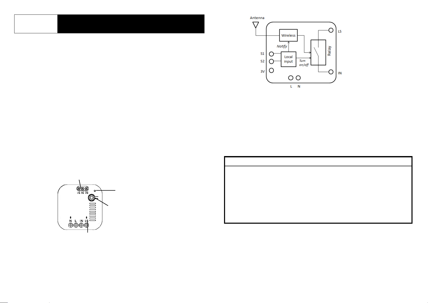
Product Overview
Switch Contact
LED
Link key/
Control button
The diagram below shows the major internal blocks of the module.
Wiring Terminals
Safety Precautions before Installation
Be sure to isolate or switch off mains power before installing or
maintenance.
Avoid installing the unit in stormy or raining weather.
Do ensure that the power supply circuit is protected by a 16 amp circuit
breaker or suitable equivalent fuse.
IMPORTANT
Installation must be performed by skilled technicians who are informed about the
standards and technical requirements of the appliance and its proper installation.
Note that the In-Wall On/Off Module is designed to be installed in a wall switch
box to operate.
Check your local codes as they apply to your situation. If the house wiring is of
aluminum, consult with an electrician about proper wiring methods.
Before proceeding with the installation, TURN OFF THE POWER TO THE
LIGHTING CIRCUIT AT THE CIRCUIT BREAKER OR FUSE BOX TO AVOID
ELECTRICAL SHOCK.
Page 2
Wiring installation
WARNING
Due to connection to AC mains, the in-wall
module should be placed inside an enclosed
casing to avoid accidents from electrical contact.
Ideally an electrical wall box should be used
whenever possible.
(Example of electrical box on right)
Terminal block to
split L terminal
L cable
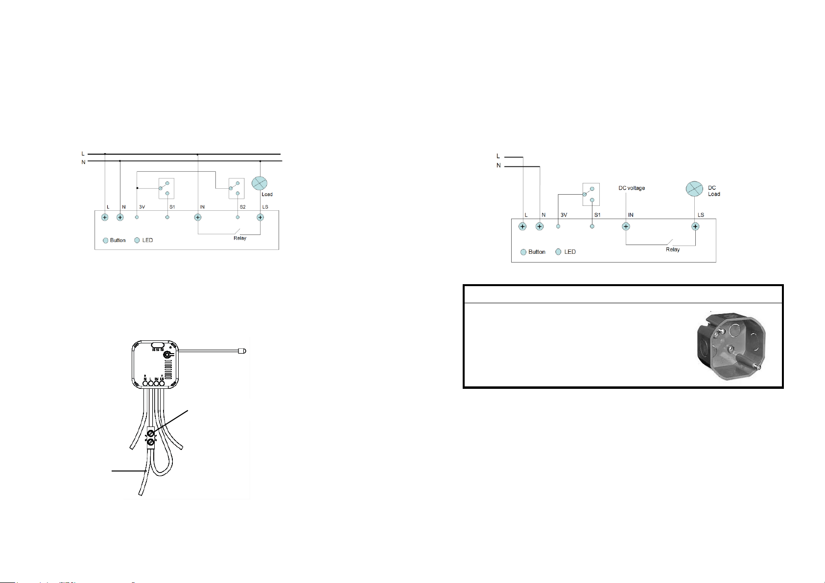
For lighting applications
1. Switch off or isolate the AC mains power before installing.
2. Remove the wall switch connected to the light. You should see an electrical wall
box where the cables of AC mains come in.
3. Wire up the module to the AC mains and the load (light) according to the wiring
diagram below. Terminal S1 connects to the wall switch to turn on/off the output.
Note: Input S2 is optional and will reverse the on/off status of S1
When connecting the “L” terminal, it is recommended to use an external terminal
block to first split the L cable from AC mains into two wires before inserting into
the module as shown below. Try to use 1.25m m2 wires for all AC connections.
4. When wiring is completed, do not assemble the module into the wall box just yet.
5. Switch the AC mains power back on to power up the unit.
For actuator applications
The module‟s dry contact output makes it easy to connect any device with all kinds
of voltages. Below is an example connection for a typical DC load such as motors or
LED light strip.
1. Switch off or isolate the AC mains power before installing.
2. Connect the AC mains and the load to the module according to the diagram
below. Here, input terminal S1 is optional.
3. Switch the AC mains power back on to power up the unit.
Page 3
Binding with HomeSys
1. Check the LED on the unit is not steady on. If it is, press the Link key once to
turn it off.
2. Log into the HomeSys account from a web browser.
3. Select “System”.
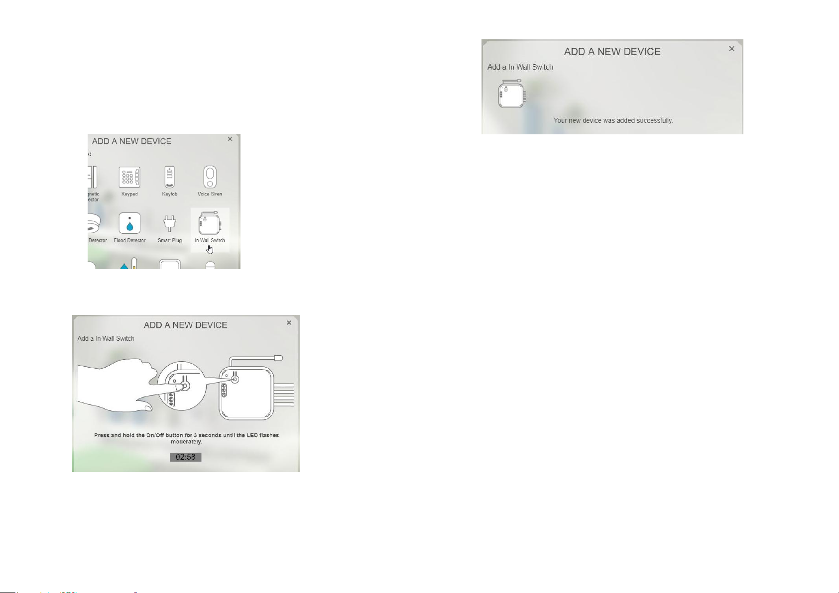
4. Select “Add a New Device”, then “In Wall Switch”.
5. Click „Next‟ again until the screen below appears. This means the gateway is
entering binding mode.
6. Press and hold the Link key for 3 seconds until its LED flashes, then release.
7. The screen below will appear in 10 seconds if the process is successful.
Note: If the LED blinks steadily for 30 seconds followed by 3 rapid flashes, this
means the binding was unsuccessful. Abort and repeat steps 4 to 6 above.
8. Once binding is complete, switch off the AC mains power again.
9. With the AC mains turned off, assemble and secure the in-wall module inside the
electrical box (or other housing) to avoid any physical contact with user.
10. Switch the AC mains on again when complete. The in-wall module is ready to
use.
Operation
The output of the module can be operated either;
- Remotely through the gateway,
- Manually through the Control button, or
- Manually using an external wall switch on terminals S1/S2.
The LED indicator on the unit will always indicate the status of the output, i.e. LED
turns on when the output is on.
By default terminals S1/S2 supports Single-Pole-Double-Throw (SPDT) type of
binary switch common in most homes. This can be configured to support
Tact/Push-button type switches, either through remote settings on the Gateway or
locally using the Control button.
To configure it locally to Tact/Push-button, press the Control button 3 times within
1.5 seconds. The led will flash 3 times indicating change is complete. Repeating this
step will toggle it back to binary switch.
Page 4

Troubleshooting
Symptom
Cause of Failure
Recommendation
Device not responding and
LED not displaying
The device is not wired to
the mains power correctly
Check if wiring is correct, or
voltage is too high or too low
LED displaying, but cannot
control On/Off status of
connected load
The connected load has its
own on/off switch
Turn the switch of the connected
load to On.
Can press button to control,
but cannot control by RF
Binding was not successful
Repeat the steps in Binding with
HomeSys
Frequency Range
868.3 MHz / 923.0 MHz
Power Input
220-240V/50Hz , 100-120V/60Hz
Maximum Power Load
Resistive load Max.11A,
Incandescent load Max. 1200W,
Fluorescent load Max.320W
Working Temperature
-10°C - 40°C
Reset to Factory Settings
To reset the unit back to factory default state:
1. Make sure the LED on the unit is turned off. If it is on, press the Link key once to
turn it off.
2. Press and hold the Link key on the module for 3 seconds until the LED turns on
and then release. The LED will start to flash.
3. Press and hold the Link key again for more than 6 seconds until the LED turns
off, then release. The LED will flash every 2 seconds indicating the unit is now
reset back to factory default settings.
Auto Binding
Once reset back to factory settings and first powered up again, the unit will attempt
to automatically bind with any U-Net compatible gateway for 30 seconds. This is
called Auto-binding.
If binding is unsuccessful after 30 seconds, Auto-binding process will stop and the
LED indicator will flash slowly every 2 seconds, implying this unit has never paired
with any device.
Note: During Auto-binding, pressing the Control button will not turn on/off the
connected load.
Auto-binding can be restarted again by disconnecting and reconnecting power to
the unit.
Specifications
Specifications are subject to change without notice
Federal Communication Commission Interference Statement
This equipment has been tested and found to comply with the limits for a Class B digital device, pursuant
to Part 15 of the FCC Rules. These limits are designed to provide reasonable protection against harmful
interference in a residential installation. This equipment generates, uses and can radiate radio frequency
energy and, if not installed and used in accordance with the instructions, may cause harmful interference
to radio communications. However, there is no guarantee that interference will not occur in a particular
installation. If this equipment does cause harmful interference to radio or television reception, which can
be determined by turning the equipment off and on, the user is encouraged to try to correct the
interference by one of the following measures:
- Reorient or relocate the receiving antenna.
- Increase the separation between the equipment and receiver.
- Connect the equipment into an outlet on a circuit different from that to which the receiver is
connected.
- Consult the dealer or an experienced radio/TV technician for help.
This device complies with Part 15 of the FCC Rules. Operation is subject to the following two conditions:
(1) This device may not cause harmful interference, and (2) this device must accept any interference
received, including interference that may cause undesired operation.
FCC Caution: Any changes or modifications not expressly approved by the party responsible for
compliance could void the user's authority to operate this equipment.
This transmitter must not be co-located or operating in conjunction with any other antenna or transmitter.
WARNING:
Do not dispose of electrical appliances as unsorted municipal waste, use separate collection facilities.
Contact your local government for information regarding the collection systems available.
If electrical appliances are disposed of in landfills or dumps, hazardous substances can leak into the
groundwater and get into the food chain, damaging your health and well-being.
When replacing old appliances with new ones, the retailer is legally obligated to take back your old
appliance for disposal at least for free of charge.
www.everspring.com
50 Sect. 1 Zhonghua Rd Tucheng
New Taipei City 236 Taiwan.
 Loading...