

Page 1
- 1 -
USC423A 868MHz GSM Alarm System
User Manual
1. Introduction
The USC423A GSM Alarm System is a control panel that is compatible with
other H-net security devices from Everspring, such as wireless sensors,
remote controls, tags, and keypad. With this system you can achieve a better
control of your home security to make your life safer and easier than ever.
2. Appearance
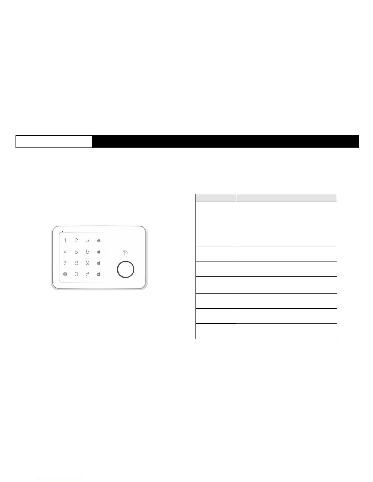
Figure 1 USC423A Appearance
3. Operation
When a key is pressed, the LED will light up and a key tone will sound (when Key
Tone is enabled).
3-1 Definition of LEDs:
LED Indication
GSM Signal LED
Flashing once every second: Registering with
host device
Flashing once every three seconds:
Successful registration with host device
Off: No AC power
[REC] LED
Flashing: Recording / On Playback /
Monitoring
On: Speaker playback
[ARM] LED
On: Arm Mode
Flashing: Arm Mode Exit Delay
[PARM] LED
On: Partial Arm Mode
Flashing: Partial Arm Exit Delay
[DISARM] LED
On: Disarm Mode
Flashing: Waiting for Code Learning / Test
Mode
[ALARM] LED
Flashing: Undergoing Host Alarm or memory
has been triggered
[TEL] LED
On: Using GSM Telephone
Flashing: GSM sending SMS
[RF ID] LED On: Reading Tag ID
Page 2
- 2 -
3-2 Operation on Control Panel
Note: Please set the Host Phone Number and set the Record Alarm Message
first so that the GSM notification can function normally.
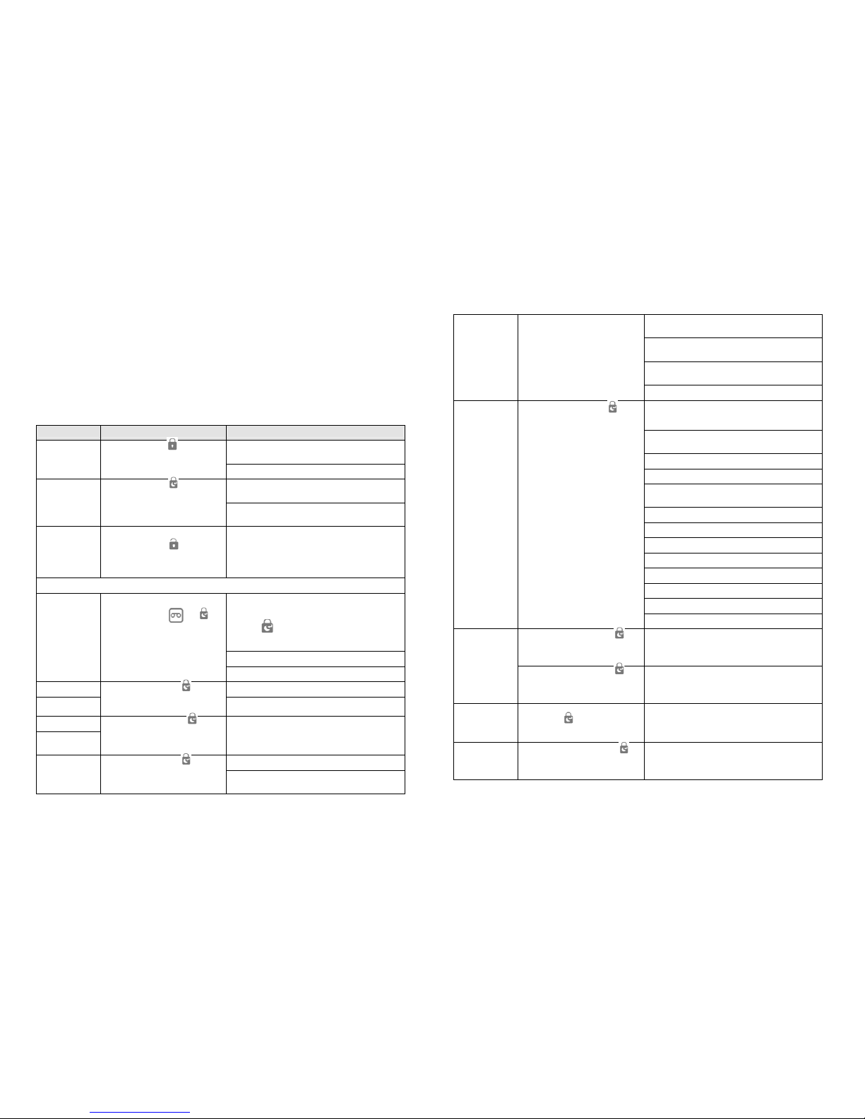
Please refer to the operation table.
Function Enter Key Explanation
Exit Delay: Arm Key LED flashes and beeps
(faster beeps at 5 second countdown)
ARM Mode
Enter password +
ARM Mode: Arm Key LED turns on
Exit Delay: Arm Key LED flashes and beeps
(faster beeps at 5 second countdown)
Partial Arm
Mode
Enter password +
Partial Arm Mode: Partial Arm Key LED turns on
DISARM Mode
Enter password +
Disarm Mode: Disarm Key LED turns on
** Please do following operations under “DISARM Mode”
1. Start recording alarm message (about 10
seconds) Playback will start automatically after
the record is complete
2. Press to stop recording if message is
shorter than 10 seconds
Record: Record Key LED will flash
Record Alarm
Message
Enter password + +
Playback: Record Key LED turns on
Alarm Type 1 Siren will sound during alarm
(Siren and
Dialer)
nter password + 01 +
(Default is ON)
Alarm Type 2
(No siren, Dialer
only)
Enter password + 02 +
Siren will not sound during alarm
DISARM Mode: Disarm Key flashes
Test Mode
Enter password + 03 +
A doorbell sound will be generated when a
device signal is received
Hold key 7 for 3 or more seconds: Test GSM
receiving signal strength
Hold key 8 for 3 or more seconds: Turn on / off
the Wireless Siren
Hold key 9 for 3 or more seconds: Test
telephone SMS
Press Disarm key to exit Test Mode
HA-70FA
Keys 1 – 8 will toggle House Code Dip Switch
positions
Dip Switch at ON position: Key LED on
Dip Switch at OFF position: Key LED off
Keys 1 – 8 LEDs will display Dip Switch ON
positions
Press Partial Arm Key to save settings
(Default Dip Switch position: 1111000)
SE822
Enable / Disable Wireless Siren
When Enabled: Key 0 LED turns on
When Disabled: Key 0 LED turns off
Press Partial Arm Key to save settings
Wireless Siren
Setting
Enter password + 04 +
(Default: Wireless Siren Disabled)
Enter password + 05+ 1 +
Turn On
RF
Anti-Jamming
Detection
Enter password + 05+ 2 +
Turn Off (Default)
Change
Password
Enter old password + 06 + new
password +
Default Password: 1234
Key Tone
Enter password + 07 + 1 +
Turn On (Default)
Page 3
- 3 -
Enter password + 07 + 2 +
Turn Off
Enter password + 08 + 1 +
Turn On
Open Door /
Window Alert
Enter password + 08 + 2 +
Turn Off (Default)
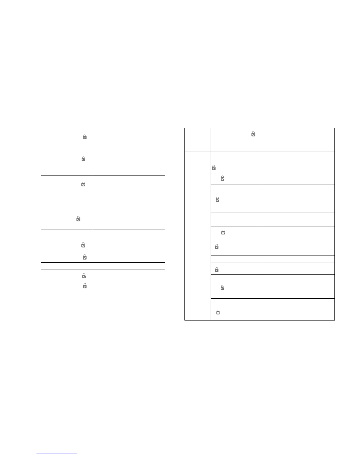
Add Remote Control
Enter password + 15 +
Add remote control or RFID tag
Add sensors
Intruder Mode
Enter password + 15 + 0 +
Sensors will trigger only when Fully Armed
Enter password + 15 + 1 +
Sensors will trigger in both Partial Armed and
Fully Armed
Delay Mode
Enter password + 15 + 2 +
Sensors will trigger only when Fully Armed, and
trigger will cause an Entry Delay
Enter password + 15 + 3 +
Sensors will trigger when Partial Armed or Fully
Armed, and trigger will cause an Entry Delay
Add Devices
24HRs Intruder Mode
Enter password + 15 + 4 +
Sensors triggered when Disarmed / Partial
Armed / Fully Armed will cause an immediate
alarm (24 hours)
Note: Fire Sensors / Flood Sensors must choose
this Type (24 hours).
Delete Sensor
Enter password + 20 + Key 1 +
Delete all sensors
Enter password + 20 + Key 1 +
1-9 +
Delete sensor 1-9
Enter password + 20 + Key 1 + 0
+
Delete all sensors after 10
Delete Remote Control
Enter password + 20 + Key 2 + Delete all remote controls
Enter password + 20 + Key 2 +
1-9 +
Delete remote control 1-9
Enter password + 20 + Key 2 + 0
+
Delete remote control 10
Delete RFID Tag
Enter password + 20 + Key 3
+
Delete all RFID tags
Enter password + 20 + Key 3 +
1-9 +
Delete RFID tag 1-9
Delete Device
Enter password + 20 + Key 3 + 0
+
Delete all RFID tags after 10
Page 4
- 4 -
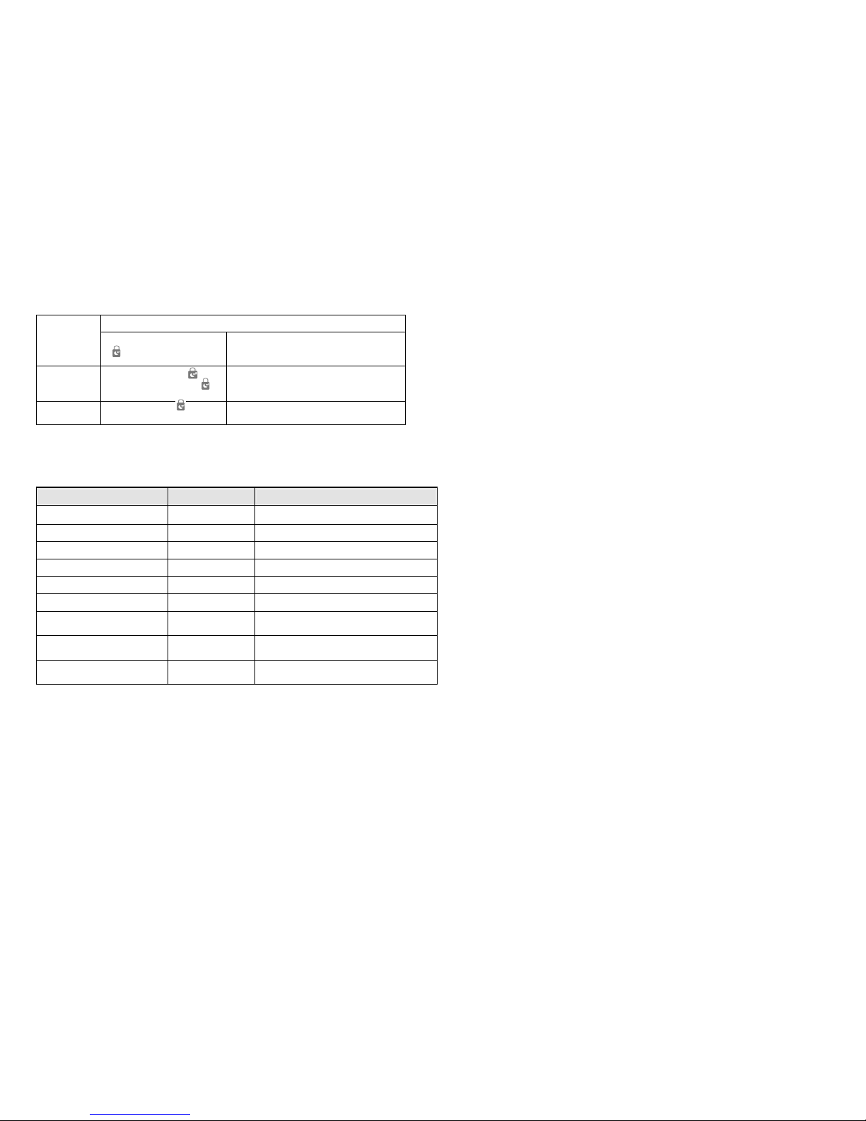
Delete Wireless Keypad
Enter password + 20 + Key 4
+
Delete wireless keypad
Add/Change
Host Numebr
Enter password + 66 +
+Mobile Phone Number +
The host number will receive an operation
succeeded confirmation SMS
Reset to Factory
Setting
Password + 0000 +
(Default Password: 1234)
3-3 Special Key Operation
Function Operation Explanation
Speed Dial TEL_1 Hold 1 Speed dial phone number set 1
Speed Dial TEL_2 Hold 2 Speed dial phone number set 2
Speed Dial TEL_3 Hold 3 Speed dial phone number set 3
Speed Dial TEL_4 Hold 4 Speed dial phone number set 4
Speed Dial TEL_5 Hold 5 Speed dial phone number set 5
PANIC Hold 9 Generate a Call for Help Alarm
Play Alarm Message Hold Record
Test playback of the user’s recorded
alarm message
All Area Alarm Mode (Single
Key)
Hold Arm Key
May only enter this mode under Disarm
Mode
Partial Area Alarm Mode
(Single Key)
Hold Partial Arm
Key
May only enter this mode under Disarm
Mode
3-4 Telephone Functions
3-4-1 Telephone call: Enter the number keys then press Telephone Key to
call. Press Telephone Key again to hang up.
3-4-2 Answer telephone: A call tone will sound when someone calls. Press
the Telephone Key to answer, and press it again to hang up. Hold the
Telephone Key for 3 seconds to reject the call.
3-4-3 DTMF Key: Number keys may be pressed during a call, with Record
Key as * and holding Record Key for more than 0.5 seconds as #.
3-5 System Arm / Partial Arm / Disarm Instructions
3-5-1 Arm Mode Setup
a. Enter the password + Arm Key. A long beep will sound if the password is
correct. Three beeps will sound if the password is incorrect.
b. If the password is correct, the system will enter the Exit Delay countdown.
The Arm LED and beep tone will flash and sound once every second.
c. When the countdown reaches 5 second, the beep tone will sound twice
every second.
d. After the countdown is complete the system will time out and enter Arm
Mode. The Arm LED will light on.
3-5-2 Partial Arm Mode Setup
a. Enter the password + Partial Arm Key. A long beep will sound if the
password is correct. Three beeps will sound if the password is incorrect.
b. If the password is correct, the system will enter the Exit Delay countdown.
The Partial Arm LED and beep tone will flash and sound once every
second.
c. When the countdown reaches 5 second, the beep tone will sound twice
every second.
d. After the countdown is complete the system will time out and enter Partial
Arm Mode. The Arm LED will light on.
3-5-3 Disarm Mode Setup
a. Enter the password + Disarm Key. A long beep will sound if the password
is correct. Three beeps will sound if the password is incorrect.
b. If the password is correct, the system will enter Disarm Mode.
NOTE: Remote Control, Wireless Keypad, and SMS can be used to
operate Arm / Partial Arm / Disarm setup. Tags can be used to
Disarm (An SMS will be sent to the Host Phone Number if
Disarmed from Fully Armed). SMS content can be modified by
Tag Names for Tags 1-4 (e.g. “Jack came home”, “Daniel
disarmed”).
3-6 Test Mode Instructions
a. Press password + 03 to enter Test Mode.
b. Time out for test mode is 10 minutes, with an additional 10 minutes if
testing is done. Press the Disarm Key if you wish to exit Test Mode.
Page 5

- 5 -
c. If a device signal is received in Test Mode the doorbell would sound and
indicate with LEDs 1 to 9 (LED 1 – 9 indicates Sensor Zone 1 – 9, Remote
1 – 9, or Tag 1 – 9. Other indications would be LED 0)
If the device is a sensor, the Sensor Type will be indicated as below:
Arm LED on: indicates the Sensor will only trigger when Fully Armed
Partial LED on: indicates the Sensor will trigger when Fully Armed or
Partial Armed
Alarm LED on: indicates the Sensor will trigger an immediate alarm (24
hours) when Fully Armed / Partial Armed / Disarmed.
d. Press 7 for 3 or more seconds during Test Mode would display the GSM
signal strength indicated as: LED 1 (Good), LED 2 (Normal), LED 3 (Poor),
LED 4 (No Signal / SIM card registration failure / No SIM card).
e. Press 8 for 3 or more seconds during Test Mode would send a System On
/ Off command from the Wireless Siren.
f. Press 9 for 3 or more seconds during Test Mode would send a test SMS
(including the current Alarm Mode, Delay Time, Siren On/Off, and Alarm
Time) to the host mobile phone number.
3-7 Alarm Procedure:
When an alarm is triggered the Alarm LED will flash and the alarm will
sound (depending on your Alarm Type and Alarm Time settings) with an
SMS / call notification (depending on your Alarm message and SMS
setting). LEDs 1 – 9 will also indicate Sensor Zone 1 – 9, Remote 1 – 9, or
Tag 1 – 9. LED 0 will light on for other situations. For Alarm LED, enter
“Password + Disarm Key” to clear Alarm Memory. The default time for
Siren Alarm is 3 minutes.
3-8 Open Door / Window Alert:
When set to On and entering Fully Armed or Partial Armed, the door /
window sensors will be checked depending on alarm mode. If sensor
shows Open then the device will beep 10 seconds, and the LED will show
1 – 9 for Sensors 1 – 9 (0 for other Sensor Zones). After the alert has
ended it will enter the configured warning procedure (if all doors / windows
are normal the alert sounds will turn off).
You may also check beforehand:
Pressing the Arm Key will check all doors and windows under Fully Armed
and display LED opened doors or windows for 3 seconds.
Pressing the Partial Arm Key will check all doors and windows under
Partial Armed and display LED opened doors or windows for 3 seconds.
3-9 RF Anti-Jamming Function
When Anti-jamming is set to on, the device will send an SMS to the Host
Phone Number when RF jamming is detected under Arm Mode.
3-10 One Key Alarm Mode
Under Disarm Mode:
Press Arm Key for 3 or more seconds to enter Arm Mode;
Press Partial Arm Key for 3 or more seconds to enter Partial Arm Mode.
3-11 Disarm Threat Password
Threat Password is your normal password + 1.
For example: normal password 1230 will have a threat password of 1231
Normal password of 9999 will have a threat password of 0000.
An SMS will be sent to the Host Phone Number when using a threat
password to disarm.
3-12 Sensor Low Battery Indication
When a Sensor Low Battery signal is received an SMS will be sent to Host
Phone Number (The sensor will send a second SMS after a minimum
interval of 7 days).
3-13 Restore to factory settings with the Reset button:
a. Turn off all power
b. Press and hold the Reset button (next to the DC-Jack) then restart the
device. One beep will sound.
c. 5 beeps will sound to indicate the device has been restored to factory
settings.
d. Default password is: 1234. For other default values please see the Quick
Guide.
4. Alarm Message Playback and SMS Functions
Device SIM card setup and installation instructions:
a. Unlock the SIM card before use. PIN code or PUK code not required.
b. Do NOT set the SIM card phone number to host phone number or regular
SMS phone number.
c. Ask your local carrier to disable voice message function of this SIM card.
d. As alarm messages and sending SMS require fees, please inquire with
your local carrier about their charging standards.
Page 6
- 6 -
e. Please carefully select the installation position of your device, as to make
sure the GSM has good signal. Please see Test Mode Point 4.
f. The SIM card must not be expired.
g. The “Show Caller ID” function must be enabled on the mobile phones for
the host phone number and SMS phone number for the host to determine if
the phone number is authorized to use the SMS function.
4-1 Alarm Message Play Function
4-1-1 Alarm Message Play Time: maximum cycle length is 30 seconds.
4-1-2 Record Alarm Message: the Help message can be recorded; Alarm
message up to 10 seconds, and will be played every time when a
condition is triggered.
4-1-3 Replay Alarm Message: hold the Record button to play the Alarm
message.
4-1-4 Confirm Telephone Times: the default is 3 times. Pressing the “*”
button on a remote phone will enter the remote control procedure. Press
8 again to confirm and the confirmed call will be temporarily canceled.
When confirmed times have been reached all phone calls will be
canceled.
4-1-5 Call Attempts: the default is 3 times. All attempted calls will count as 1
times before the Confirm Times has been reached. The call will stop
when the maximum call value has been reached.
4-2 Special Functions
4-2-1 Warning SMS Notice and Host Parameter Setup
When the host generates an alarm, an SMS will be sent first from the
preset SMS phone number to notify the user on the condition.
4-2-2 Alarm Voice Automatic Call
When the host generates an alarm, the preset voice telephone number
and help message will automatically call and notify the user of an alarm
condition. Please refer to the Trigger Call Procedures.
4-2-3 System Disarm Notification
When the RFID Tag is on the Host tag sensor, an SMS will be sent to the
Host Phone Number if Fully Arm is set to Disarm and notify the user on
who disarmed the system.
4-3 Built-In Automatic Voice Dial
4-3-1 How to enter Reverse Control:
The user may press “*” when hearing the USC423A alarm call. The alarm
will stop and the device will enter “Reverse Control” mode and wait for
function input. Press the “#” or wait 30 seconds to end the call (Listen In
or Two Way Talk excluded).
4-2-2 Reverse Control Procedures:
a. Press “*” and input Key (0 – 9 and *) after the message to enter Remote
Control Procedures. Timeout will occur if no Keys were input after 30
seconds.
b. When Key = 1 (Full Arm and send SMS)
c. When Key = 2 (Part-Arm and send SMS)
d. When Key = 3 (Set the Siren to turn on Alarm and send SMS)
e. When Key = 4 (Set the Siren to turn off Alarm and send SMS)
f. When Key = 6 (Listen to the Alarm message again)
g. When Key = 7 (Enter Listen In Mode. Timeout will occur after 5 minutes)
h. When Key = 8 (Cancel telephone notice and send SMS)
i. When Key = 9 (Enter Two Way Talk Mode. Timeout will occur after 5
minutes)
j. When Key = 0 (Disarm and send SMS)
4-2-3 Trigger Call Procedures
When an event triggers, the device will call the preset number and play
the alarm message for 30 seconds. Pressing a Key will enter Remote
Control. The call will end after 30 seconds and contact the next set of
numbers and repeat the steps.
4-2-4 SMS Functions
Setup SMS Sent Operation SMS in Return
Operation
Menu 1
#
0 Disarm
1 Arm
2 Partial Arm
3 Two-way Talk
4 Listen In
00 System Status
? Phone Number Setup
Page 7

- 7 -
Operation
Menu 2
?
5 Alarm Call Phone Number Set
6 Alarm SMS Phone Number Set
8 Speed Dial Phone Number Set
?? System Setup
Operation
Menu 3
??
91-99 Change Zone Name
10 Change RFID Tag Name
11 Enter & Exit Delay Time
12 Siren Volume
13 Siren Ring Time
Disarm 0 System Disarmed
Arm 1 System Armed
Partial 2 System Partial Armed
Two Way
Talk
3
Call back from
Alarm system
console
(Note 7)
Listen In 4
Call back from
Alarm system
console
(Note 7)
System
Status
Display
00
System Disarmed/ System
Armed/ System Partial Armed
Entry & Exit Delay Time: xx
Seconds
Siren Volume: Mute/Low/High
Siren Ringing Time: xx Minutes
Set Alarm
Voice Phone
Number
5(Note1) (Note 5)
TEL:
1.
2.
3.
4.
5.
Forward->
Edit->Send
TEL:
1. 0932XXXXXX
2. 0922XXXXXX
3. 0928XXXXXX
4. 0965XXXXXX
5. 0932XXXXXX
Set Phone Number Successfully
Set Alarm
SMS Phone
Number
6 (Note1) (Note 5)
SMS:
1. 0932XXXXXX
2. 0922XXXXXX
3. 0928XXXXXX
4.
5.
Forward->
Edit->Send
SMS:
1. 0932XXXXXX
2. 0922XXXXXX
3. 0928XXXXXX
4. 0936XXXXXX
5. 0921XXXXXX
Set Phone Number Successfully
Page 8

- 8 -
Set Speed
Dial No. (5
sets)
8(Note1) (Note 5)
SPEEDDIAL:
1.
2.
3.
4.
5.
Forward->
Edit->Send
SPEEDDIAL
1. 0928XXXXXX
2. 0965XXXXXX
3. 022655XXXX
4.
0021626572XXX
X
5. 08532XXXX
Set Phone Number Successfully
Change Zone
1 Name
91
(Note 2)
(Note5)
Zone1 Name:
Zone1
Forward->
Edit->Send
Zone1 Name:
Entrance Door
Sensor1
Set Zone Name Successfully
Change Zone
2 Name
92
(Note 2)
(Note5)
Zone2 Name:
Zone2
Forward->
Edit->Send
Zone2 Name:
Entrance Door
Sensor2
Set Zone Name Successfully
Change Zone
3 Name
93
(Note 2)
(Note5)
Zone3 Name:
Zone3
Forward->
Edit->Send
Zone3 Name:
Entrance Door
Sensor3
Set Zone Name Successfully
Change Zone
4 Name
94
(Note 2)
(Note5)
Zone4 Name:
Zone4
Forward->
Edit->Send
Zone4 Name:
Entrance Door
Sensor4
Set Zone Name Successfully
Change Zone
5 Name
95
(Note 2)
(Note5)
Zone5 Name:
Zone5
Forward->
Edit->Send
Zone5 Name:
Entrance Door
Sensor5
Set Zone Name Successfully
Page 9

- 9 -
Change Zone
6 Name
96
(Note 2)
(Note5)
Zone6 Name:
Zone6
Forward->
Edit->Send
Zone6 Name:
Entrance Door
Sensor6
Set Zone Name Successfully
C
hange Zone
7 Name
97
(Note 2)
(Note5)
Zone7 Name:
Zone7
Forward->
Edit->Send
Zone7 Name:
Entrance Door
Sensor7
Set Zone Name Successfully
Change Zone
8 Name
98
(Note 2)
(Note5)
Zone8 Name:
Zone8
Forward->
Edit->Send
Zone8 Name:
Entrance Door
Sensor8
Set Zone Name Successfully
Change Zone
9 Name
99
(Note 2)
(Note5)
Zone9 Name:
Zone9
Forward->
Edit->Send
Zone9 Name:
Entrance Door
Sensor9
Set Zone Name Successfully
Change RFID
Tag Names
10
(Note 2)
(Note5)
Tag Names:
1.
2.
3.
4.
Forward->
Edit->Send
Tag Names:
1. Jack
2. Daniel
3. Henry
4. Joe
Set Tag Names Successfully
Set Entry &
exit Delay
Time
11 (Note 5)
Entry & Exit Delay Time(0-240
sec.):
15
Forward->
Edit->Send
Entry & Exit
Delay Time
(0-240 sec.):
10
Set Delay Time Successfully
Set Siren
Volume
12 (Note 5)
Siren Volume (0 Mute, 1 Low, 2
High): 2
Page 10

- 10 -
Forward->
Edit->Send
Siren Volume (0
Mute, 1 Low, 2
High): 1
Set Siren Volume Successfully
Set Siren
Alarm
Duration
13 (Note 5)
Siren ringing time (1-9 minutes):
3
Forward->
Edit->Send
Siren ringing
time (1-9
minutes):
5
Set Siren Time Successfully
0001 English(Note 5) Set Language Successfully
0034 Spanish(Note3) Requirements Not Allowed
0886
Traditional
Chinese (Note3)
Requirements Not Allowed
System
Language
Change
0086
Simplified
Chinese (Note3)
Requirements Not Allowed
Status
Report
SMS Sent
SMS in Return
AC Adaptor
Power Off
(Note 6) System AC Power Loss
AC Adaptor
Power On
(Note 6) System AC Power Return
Tag
Disarmed
(Note 6)
For Tag 1-Tag 4:
Send "Tag name"
For Other Tags:
Send "Tag xx "
Zone Trigger
For Zone 1-Zone 9:
Send "Zone name” is triggered
For Other Zones:
Send "Zone xx” is triggered
Zone Tamper
For Zone 1-Zone 9:
Send "Zone name” tamper is
triggered
For Other Zones:
Send "Zone xx” is triggered
Zone Low
Battery
(Note 6)
For Zone 1-Zone 9:
Send "Zone name” battery is low
For Other Zones:
Send "Zone xx” battery is low
Console
Tamper
Console tamper is triggered
Keypad
Tamper
Keypad tamper is triggered
Console
Panic
Emergency help notify
Page 11

- 11 -
Remote
Panic
Emergency help notify
Phone
number
invalided
Unauthorized Phone Number
SMS
Command
invalided
Requirements Not Allowed
Alarm call
confirmed
The Phone Call Confirmed
Duress code
(Note 6) Duress code is sent
Anti-jamming
(Note 6) Signal has been jammed
Note1: Maximum length for telephone numbers is 20 digits. Only numbers 0 –
9 and “,” can be used. For example, phone number 0222606868 with
extensions 1234 will be input as: “0222606868,1,2,3,4”. If the length
exceeds 20 digits, only the first 20 digits will be saved, and the rest will
be deleted.
Note 2: Maximum length for Zone Names and Tag Names is 24 characters
(letters and numbers. No Chinese). If the length exceeds 24 characters,
only the first 24 characters will be saved, and the rest will be deleted.
Note 3: This language is currently unavailable.
Note 4: Do NOT add or delete spaces or other symbols, or change Title
content, as SMS configuration may fail if those are changed. For
example, when setting Zone1 Name, the zone name must be entered
under Title (not after). Please refer to the examples listed above.
Note 5: Only the host mobile phone number can use the SMS function.
Note 6: Special condition SMS will only be sent to the host mobile phone
number.
Note 7: Two Way Talk and Listen In must be picked up within 25 seconds, or
the host will end the call. A failure SMS will be sent if dial back is
unsuccessful.
Note 8: Send a SMS “???” from an authorized mobile phone number to
receive the host model number and software version.
5. Troubleshooting
5-1 System Reset:
The user may use the system reset button to return the device to factory
default settings. The default password is “1234”. Please note that all
configurations (including recorded alarm messages, contact lists, and
learnt ID codes will be deleted):
a. Take the device off the wall.
b. Remove all power sources (including batteries and DC-jack).
c. Press the reset button on the back of the device and insert the
batteries (or DC-jack).
d. The LED will turn on to indicate the system is starting. 5 short beeps
will sound when the system is reset to factory settings.
5-2 The USC423A cannot register with a GSM host (GSM Net LED
flashes rapidly):
a. SIM card not inserted or bad contact.
b. SIM card needs to be unlocked before use (use a mobile phone to
setup) to cancel the input of PIN code or PUK code.
c. Change the position of the USC423A.
d. Remove AC power and batteries and insert the SIM card again.
e. Make sure the SIM card is not expired.
5-3 Authorized SMS mobile phone number cannot be configured
or receive SMS:
a. The Show Caller ID function of the mobile phone with the SIM card
must be turned on. The host can then determine if the number was
authorized.
b. Only phone numbers set as the Admin user (Host phone number) may
configure parameters such as Voice, SMS, Speed Dial numbers, delay
time, Siren, volume, and starting time. Normal SMS numbers will not
be accepted.
c. If GSM is busy or has bad signal, the SMS may be delayed or not sent.
d. When operating SMS from a mobile phone, please wait for the
Page 12
- 12 -
USC423A to return the SMS before operating the next SMS. Resend
the SMS if one minute has passed and the USC423A return SMS is
still absent.
e. When operating SMS from a mobile phone, if there are no responses
the reason might be the sent SMS is not an acceptable command.
Please refer to “SMS Functions”.
5-4 GSM Net LED is off:
a. Check the AC adaptor to see if it’s properly plugged in and check the
power LED to see it it’s on. The GSM will shut down partial power when
it is not connected to AC power to extend usage time.
b. Remove all power sources (including batteries and AC power), insert
them back and try again.
Specifications
Operating temperature range -10°C to 50°C
Operating humidity 85% RH at 30°C
Adapter 9V DC 1A
Battery type Li-ion cell 2000mAh 3.7V
Transmission range Outdoors >150m (Open space) for front and sides
Frequency range 868.35 MHz
** Specifications are subject to change without notice
USC423A0517
ENVIRONMENTAL CONCERNS
Please DO NOT dispose of electrical appliances as unsorted waste, use the recycling
facilities provided by your local authorities.
Please DO NOT dispose of packaging as unsorted waste, use the recycling facilities
provided by your local authorities.
MANUFACTURER
Everspring Industry Company Limited
3F, No. 50, Sec 1
Zhonghua Road
Tucheng District
New Taipei City
23666
Taiwan
TEL: +886 2 2260 6868
FAX: +886 2 2260 1313
 Loading...