

Page 1
1
ST812 FLOOD DETECTOR
These instructions should be read in conjunction with your System Installation
and Operating Manual and be retained for future reference.
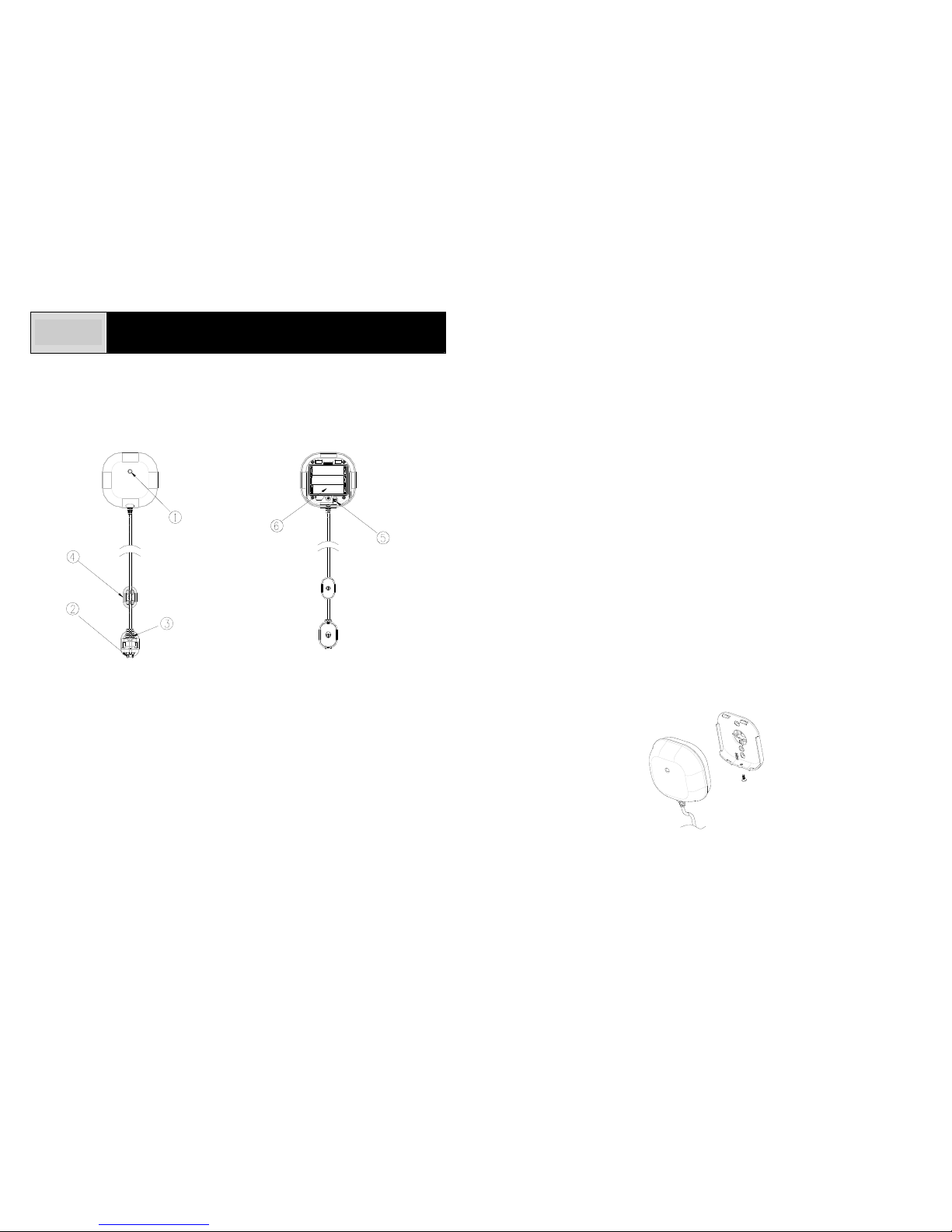
Product Layout
c Two-color Indication LE D (red & green)
d Flood Sensor
e Sensor Rack
f Flood Sensor Cable Rack
g Link Key
h Battery Compartment
Introduction
The Flood Detector is a Z-Wave
TM
enabled device and is fully compatible with any
Z-WaveTM enabled network. Z-WaveTM enabled devices displaying the Z-WaveTM logo
can also be used with it regardless of the manufacturer, and ours can also be used in
other manufacturer’s Z-Wave
TM
enabled networks. Inclusion of this Flood Detector
on other manufacturer’s Wireless Controller menu allows remote turn-on of connected
modules and their connected lighting when the Detector is triggered. Z-Wave
TM
nodes
in the system also act as repeaters if they support that function.
The Flood Detector consists of a transceiver, flood sensor and 3-meter flood sensor
cable. Protect your property from water damage! The Flood Detector is designed to
sense the presence of water in basements, yachts and many others residential and
commercial applications, providing early warning of developing floods. The Flood
Detector is designed so that the transceiver is mounted on the wall and the flood
sensor is placed in a location where water presence, such as a result of leakage or
flooding, is probable.
Upon flood detection, the Detector will beep and flash and
report its status to the node ID. Once water is released, it will report to the node ID
as well.
The Flood Detector is powered by 3 x AA 1.5V alkaline battery. When battery level
drops below unacceptable level, the Detector flashes red LED once every 30 seconds
and reports low battery status to the node ID. When this occurs, the batteries should
be replaced as soon as possible.
Power Up
1. Undo and remove the screw from the bottom edge of the transceiver . Remove the
back cover.
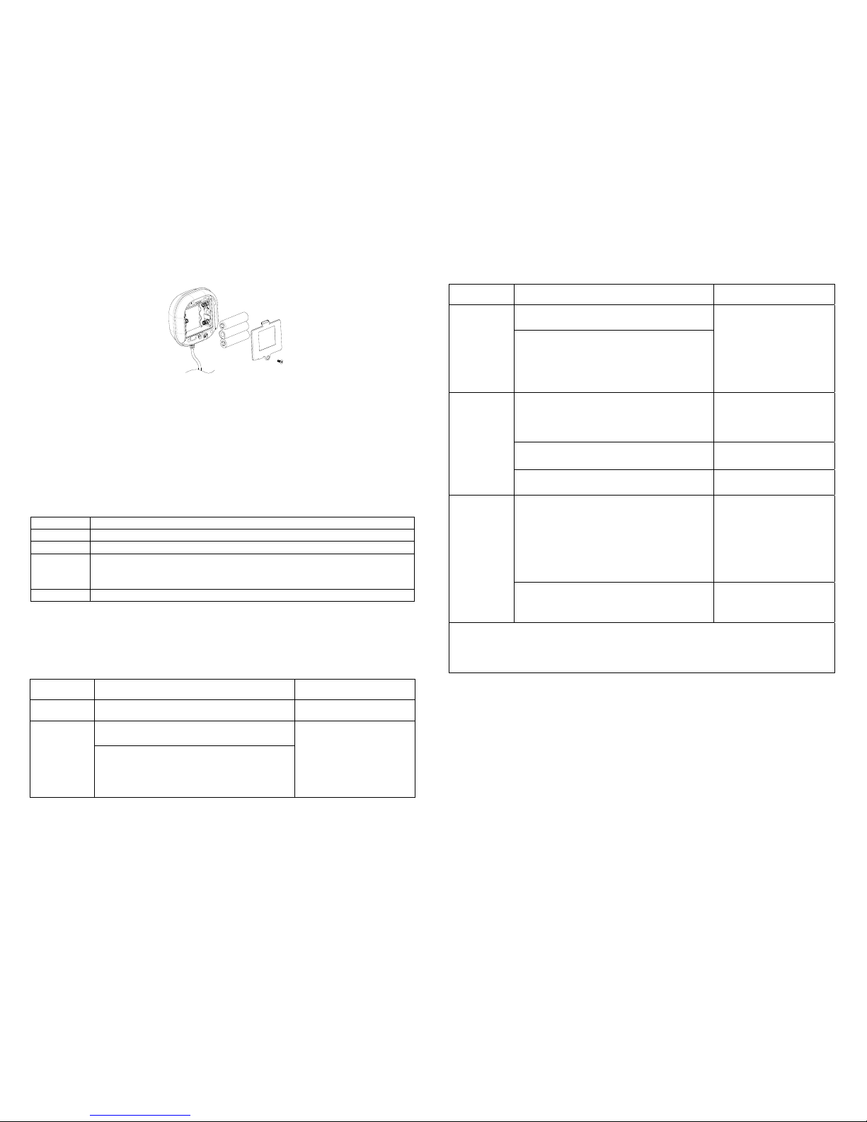
2. Unscrew the screw from the battery cover and remove the battery cover.
3. Fit 3 AA size 1.5V batteries to the battery spring.
Page 2
2
4. Refit the battery cover by fastening its screw.
Include to or Exclude from a Z-WaveTM Network
In the rear casing, there is a link key which is used to carry out inclusion, exclusion,
reset or association. When first power is applied, its two-color LED flashes on and off
alternately and repeatedly at 2-second intervals. It implies that it has not been
assigned a node ID and cannot work with Z-Wave enabled devices. Please get
familiar with the terms below before starting the operations.
Function Description
Inclusion Add a Z-Wave enabled device (e.g. Flood Detector) to Z-Wave network.
Exclusion Delete a Z-Wave enabled device (e.g. Flood Detector) from the network.
Association After inclusion, you have to define the relationship between devices. Through
association, device can be assigned as master/slave, and specify which
slave is going to be controlled by which master.
Reset Restore Flood Detector to factory default.
The table below lists an operation summary of basic Z-Wave functions. Please refer
to the instructions for your Z-Wave
TM
Certificated Primary Controller to access the
setup function, and to include/exclude/associate devices.
Function Description Audible & Visual
Indication
No node ID The Z-Wave Controller does not allocate a
node ID to the Detector.
2-second on, 2-second off
1. Have Z-Wave Controller entered
inclusion mode.
Inclusion
2. Pressing link key three times within 1.5
second will enter inclusion mode.
The
detector will stay “awake” for 10
minutes to allow time for setting and
device status enquiring.
Beep once whenever link
key is pressed once.
Function Description Audible & Visual
Indication
1. Have Z-Wave Controller entered
exclusion mode.
Exclusion
2. Pressing link key three times within 1.5
second will enter exclusion mode. The
detector will stay “awake” for 10
minutes to allow time for setting and
device status enquiring.
Beep once whenever link
key is pressed once.
1. Press link key three times within 1.5
second.
The detector will stay “awake”
for 10 minutes to allow time for
setting and device status enquiring.
Beep once whenever link
key is pressed once.
2. Within 1 second, press and hold the link
key until beep tone stops.
Long beep for 5 seconds
Reset
3. IDs are excluded and all of preset
value will be reset to factory default.
2-second on, 2-second off
1. Have Z-Wave Controller entered
association mode.
Or Pressing link key three times within 1.5
second will enter association mode.
The
detector will stay “awake” for 10
minutes to allow time for setting and
device status enquiring.
Beep once whenever link
key is pressed once.
Association
2. There are two groupings - 1 and 2. Refer
to Z-Wave’s Groups as described on
page 3 & 4.
ÚIncluding a node ID allocated by Z-Wave Controller means inclusion. Excluding a node
ID allocated by Z-Wave Controller means exclusion.
ÚFailed or success in including/excluding the node ID can be viewed from the Z-Wave
Controller.
Installation
A clean smooth surface is required to mount the Flood Detector securely. The length
of flood sensor cable is 3 meters. If a 3-meter cable is too long, roll up the cable and
fasten it by twist ties. The transceiver should be placed as high up as possible on the
wall to improve communication and to prevent it from coming into contact with water in
case of flooding. After completion of battery insertion and set up, follow the below
procedures:
Page 3
3
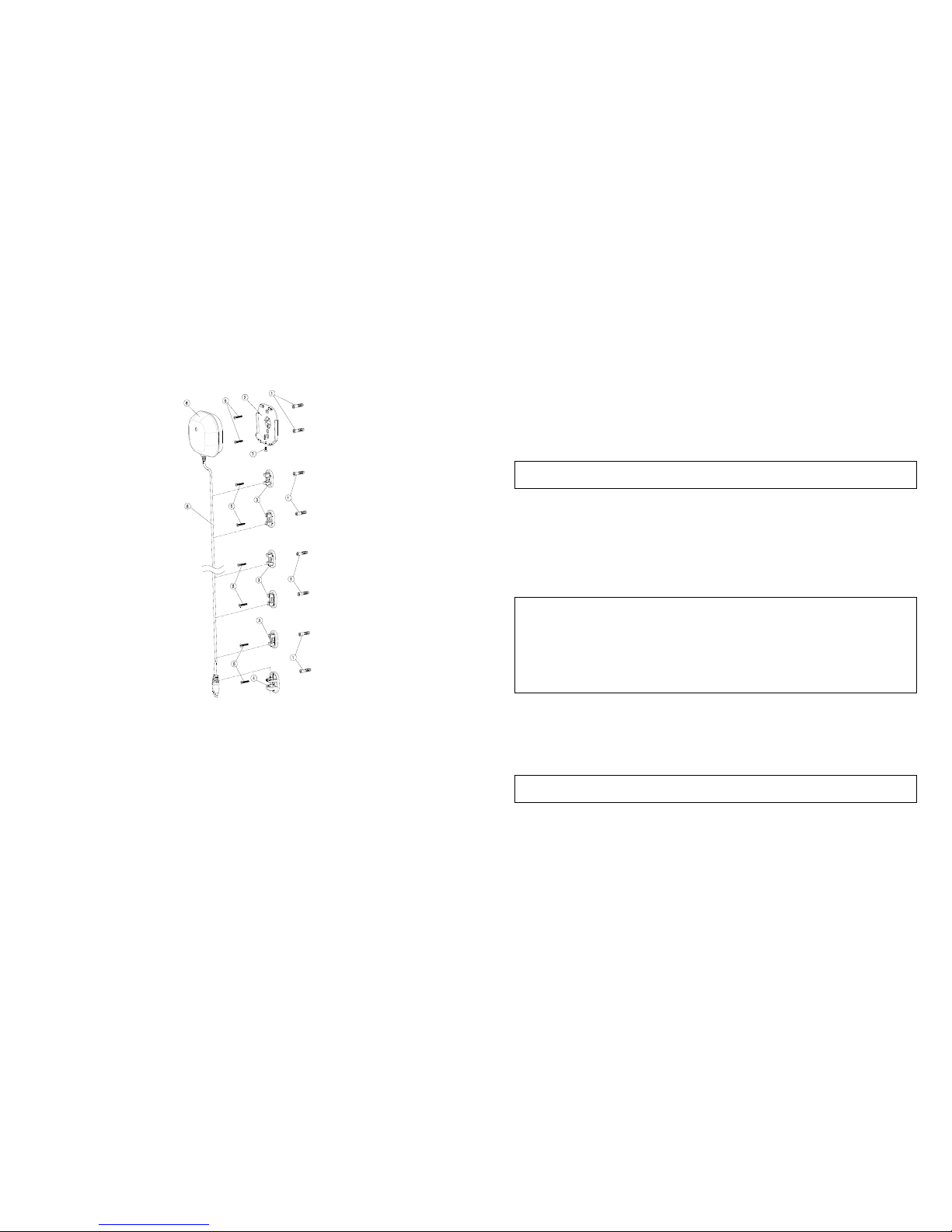
1. Attach the flood sensor near the floor.
2. Use the back cover, flood sensor cable rack and sensor rack as a template to
mark the position of fixing holes on the wall. Drill the holes and insert the plastic
wall plugs supplied respectively.
3. Fix the back cover, flood sensor cable rack and sensor rack using the fixing
screws provided.
4. Refit the transceiver to the back cover and secure with the fixing screw supplied.
5. Place the flood sensor cable and flood sensor to its rack.
Note: The transceiver should never be submerged in water.
Programming
1. Z-Wave’s Groups (Association Command Class Version 2)
The Flood Detector supports two association groups with one node sup port for
Grouping 1 and three nodes support for Grouping 2. This has the effect that when the
Detector is triggered, all devices associated with the Detector will receive the relevant
reports.
There are two kinds of reports: ALARM_REPORT and SENSOR_ALARM_REPORT.
1-1 Grouping 1 (Max. node 1)
1-1-1 Power Applied command
The Detector will send ALARM_REPORT command to the nodes of
Grouping 1 to inform the devices that the Detector is powered up.
ALARM_REPORT Command:
[Command Class Alarm, Alarm Type = 0x02, Alarm Level = 0x01]
1-1-2 Flood Event Report (Binary Sensor Report)
Once the Detector has been triggered by water, the Detector will send
SENSOR_ALARM_REPORT to the nodes of Grouping 1 to inform them
there is a flood event; meanwhile, its red LED will flash for one minute
and beep for 30 seconds. Wait till water is released,
SENSOR_ALARM_REPORT will be sent to the associated devices.
SENSOR ALARM REPORT Command:
Event Present:
[Command Class Sensor Alarm, Sensor Alarm Report, Sensor Type
Water Leak Alarm State = 255 (0xFF), Seconds = 0x00]
Event Clear:
[Command Class Sensor Alarm, Sensor Alarm Report, Sensor Type
Water Leak Alarm State = 0x00(0), Seconds = 0x00]
1-1-3 Low Battery Report (Alarm Command Class)
When the battery level of the Detector drops to an unacceptable level,
the Detector will send a low battery command to the node of Grouping 1;
meanwhile, the Detector will flash red LED once every 30 seconds.
ALARM REPORT Command:
[Command Class Alarm, Alarm Type = 0x01, Alarm Level = 0xFF]
1-2 Grouping 2 (Max. nodes 3)
1-2-1 Control other Z-Wave devices
Page 4

4
When the Detector has been triggered, it will control other Z-Wave
devices for operation by sending Basic Set command to the nodes of
Grouping 2; meanwhile, the Detector will flash red LED for one minute
and beep for 30 seconds.
Basic Set Command:
Event Present:
[Command Class Basic, Basic Set, Value = Basic set level]
Event Clear:
[Command Class Basic, Basic Set, Value = 0x00(0)]
2. Z-Wave’s Configuration
2-1 Basic Set Level
When Basic Set Command is sent where contains a value, the receiver will
take it for consideration; for instance, if a lamp module is received the Basic
Set command of which value is decisive as to how bright of dim level of lamp
module shall be.
Example:
0: OFF
1-99: ON (Binary Switch Device)
Dim Level (Multilevel Switch Device)
Function Parameter Number Size Range Default
Basic Set level 1 1 0~99 99
Configuration Command
3. Advanced Programming
3-1 Low Battery Indication
The users can also enquire the battery status of the Detector by sending
BATTERY_GET command via Z-Wave Controller. Once the Detector receives
the command, it will return BATTERY_REPORT command. The Detector will
send Battery_Level = 255 (0xFF) command to the Z-Wave Controller to inform
that the Detector is in low battery status.
BATTERY REPORT Command:
[Command Class Battery, Battery Report, Battery Level = 20%-100%]
3-2 Wakeup Command Class
The unit stays in sleep status for the majority of time in order to conserve battery
power. However, it can be woken up at specified intervals by setting
WAKE_UP_INTERVAL_SET command by Z-Wave Controller. After the unit
wakes up, it will send Wakeup Notification Command to the node ID that
requires to be reported. The minimum and maximum wakeup interval is 60
seconds and 194 days respectively. Allowable interval among each wakeup
interval is 1 second, such as 60, 61, 62 ….
4. Command Classes
The Flood Detector supports Command Classes including…
*COMMAND_CLASS_SENSOR_BINARY
*COMMAND_CLASS_BASIC
*COMMAND_CLASS_CONFIGURATION
*COMMAND_CLASS_WAKE_UP_V2
*COMMAND_CLASS_MANUFACTURER_SPECIFIC
*COMMAND_CLASS_VERSION
*COMMAND_CLASS_ASSOCIATION_V2
*COMMAND_CLASS_BATTERY
*COMMAND_CLASS_SENSOR_ALARM
Operation
1. When water is detected, the Detector flashes red LED for one minute and beeps
for 30 seconds as maximum during which an event report will be sent to the node
ID. In normal mode, the detection interval is set for one minute. If the Detector is
triggered, it will not be triggered again until one minute has elapsed, thus avoiding
false trigger.
2. When water is released, the green LED on the Detector will illuminate once.
3. When the battery level on the Detector drops to a certain level, the red LED will
flash once every 30 seconds and an event report will be sent to the node ID.
Page 5
5
Troubleshooting
Symptom Possible Cause Recommendation
Batteries have not been
fitted or insufficient
battery power
Check out if batteries are
fitted or replace new
batteries
LED not indicating and
working
Break down Do not open up the
Detector and send it for
repair
No beep sound and
LED not indicating when
triggered
Not carry out inclusion Include a node ID allocated
by Z-Wave Controller
SPECIFICATION
Battery Type 1.5V AA x 3 pieces
Battery Life About 1 year, @25°C standby mode
Operating Frequency 868.42MHz (ST 812-1) / 908.42MHz (ST812-2)
ZDK Version V5.02
A501111533R
Federal Communication Commission Interference Statement
This equipment has been tested and found to comply with the limits for a Class B
digital device, pursuant to Part 15 of the FCC Rules. These limits are designed to
provide reasonable protection against harmful interference in a residential installation.
This equipment generates, uses and can radiate radio frequency energy and, if not
installed and used in accordance with the instructions, may cause harmful
interference to radio communications. However, there is no guarantee that
interference will not occur in a particular installation. If this equipment does cause
harmful interference to radio or television reception, which can be determined by
turning the equipment off and on, the user is encouraged to try to correct the
interference by one of the following measures:
- Reorient or relocate the receiving antenna.
- Increase the separation between the equipment and receiver.
- Connect the equipment into an outlet on a circuit different from that to which the
receiver is connected.
- Consult the dealer or an experienced radio/TV technician for help.
This device complies with Part 15 of the FCC Rules. Operation is subject to the
following two conditions: (1) This device may not cause harmful interference, and (2)
this device must accept any interference received, including interference that may
cause undesired operation.
FCC Caution: Any changes or modifications not expressly approved by the party
responsible for compliance could void the user's authority to operate this equipment.
This transmitter must not be co-located or operating in conjunction with any other
antenna or transmitter.
WARNING:
Do not dispose of electrical appliances as unsorted municipal waste, use separate
collection facilities.
Contact your local government for information regarding the collection systems
available.
If electrical appliances are disposed of in landfills or dumps, hazardous substances
can leak into the groundwater and get into the food chain, damaging your health and
well-being.
When replacing old appliances with new once, the retailer is legally obligated to take
back your old appliance for disposal at least for free of charge.
 Loading...