

Page 1
1
SOLAR-POWERED POOL ALARM SYSTEM FOR SAFETY AID
TO READ ATTENTIVELY AND TO PRESERVE FOR FUTURE CONSULTATION
WARNING
This system is simply a safety aid which announces a danger (or risk of danger) when an
equivalent of 8kgs (18 pounds) object falls into a unsupervised swimming pool. The fast
intervention in less than 3 min of a responsible adult is obligatory when the signal of alarm
happens. Ensure the construction of the pool wall is solid enough, thus it can stand the drilling
of the screws and wall plugs without cracking the pool wall. After installation, ensure the pool
alarm itself cannot be shaken, otherwise it will affect the performance of pool alarm detection. In
the event of any injury or death to any person arising out of misuse, abuse, negligence, accident
or alteration, Everspring Tech USA, Inc., will not be liable for any consequence caused.
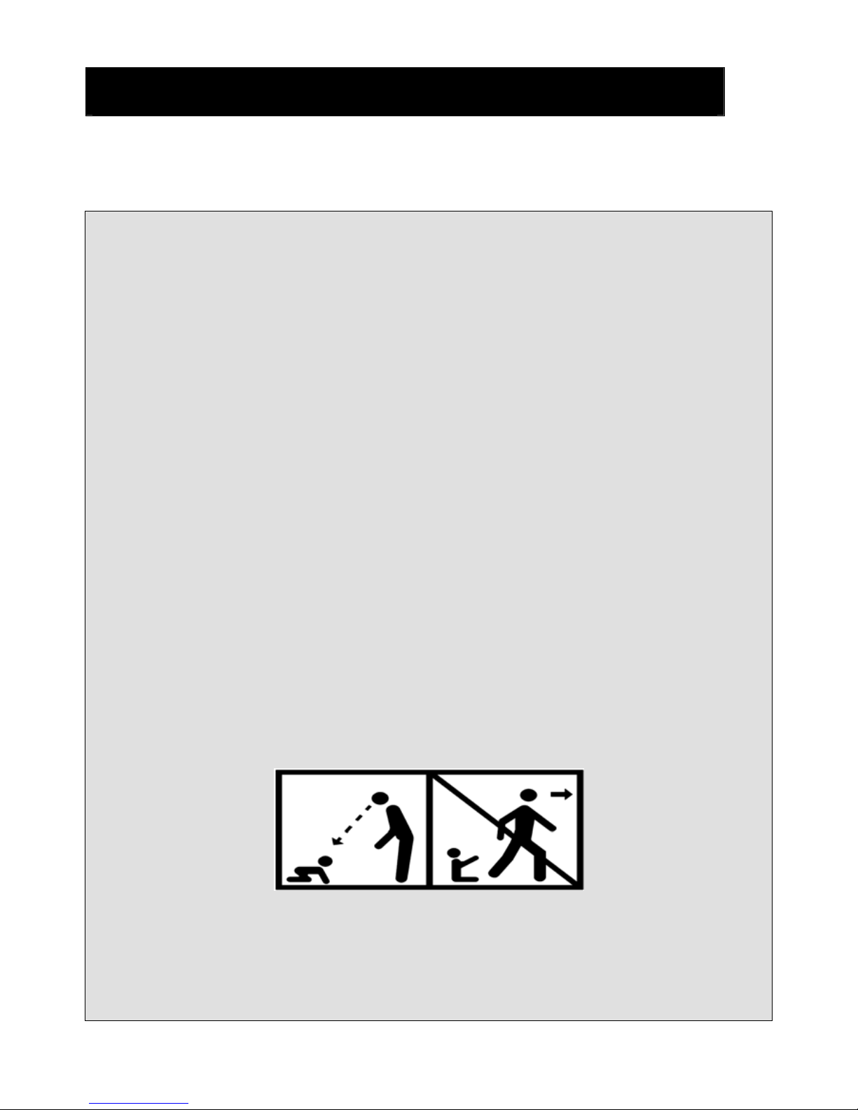
This system does not replace the good direction nor with the several liability. The purpose of it is
not to either replace the vigilance of the parents and/or the responsible adults, which remains the
essential factor for the protection of the children with less than five years;
The user who turns OFF the system must be conscious that the human monitoring must take
over;
It is imperative to react when the signal of alarm happens;
The greatest vigilance of the responsible parent /adult is necessary between the end of the bathe
and the reactivation of the product;
Never leave children unattended in or aro und the s wimming po ol or spa. Children under five years of
age are at the greatest risk for in jury or death in po ol-rel ated acc idents.
In the event of possibility of stroke with against current: "Cancel the stroke with against current at
the end of the bathe to allow the reactivation of the product".
Some of cleaning robots as a plunger robots type are incompatible with the systems of detection
of immersion
Page 2
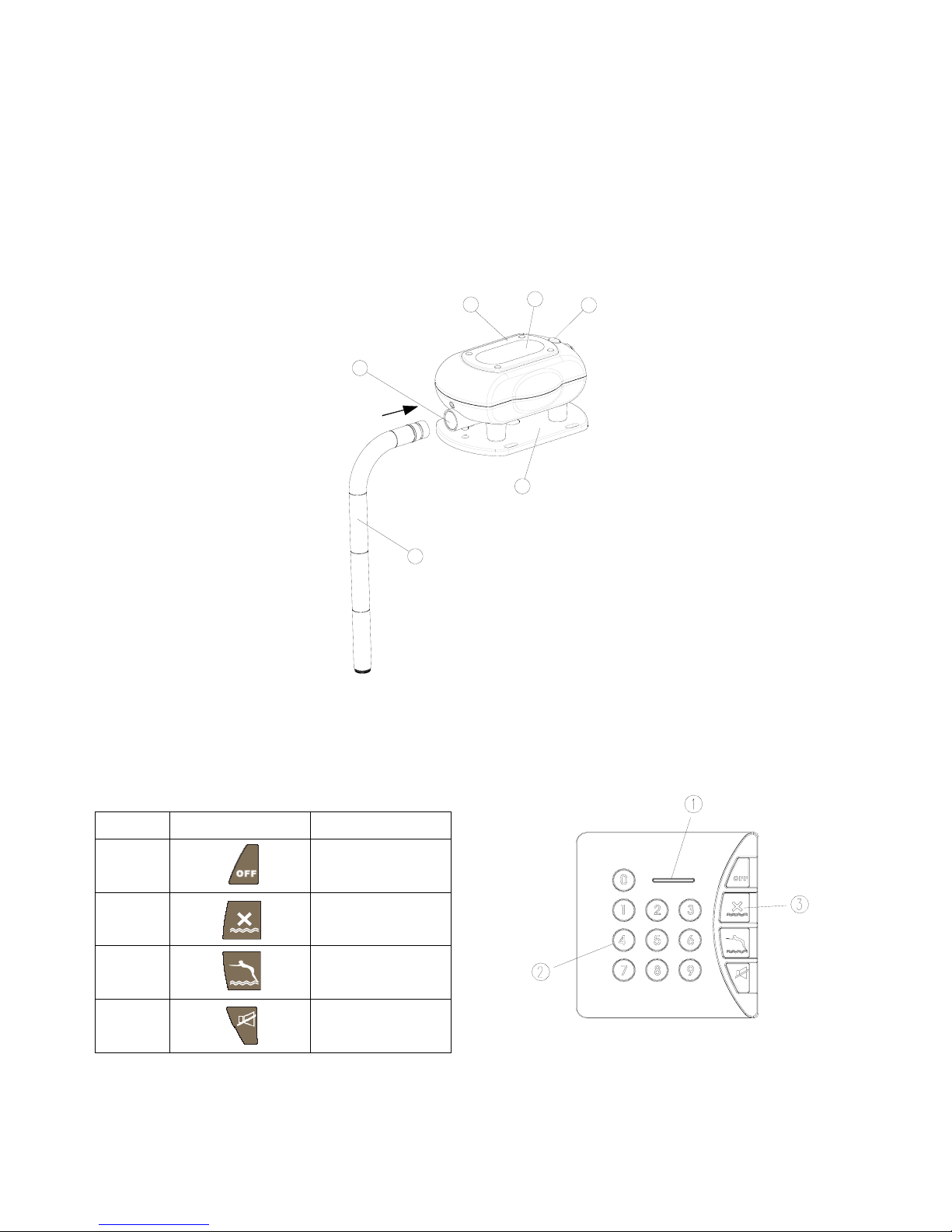
PRODUCT LAYOUT
Solar-powered Wireless Pool Alarm (ST113)
Battery Cover
Solar Panel
Start Button
Base
Sensing Compartment
Detachable Tube
3
1
2
5
4
6
Wireless Keypad (SA802)
Setting/Low Battery LED
2
Keypad
Function Key
Sequence
Function Key Description
1
System Off
2
System On
3
Auto
4 Disarm the alarm
sound
Page 3
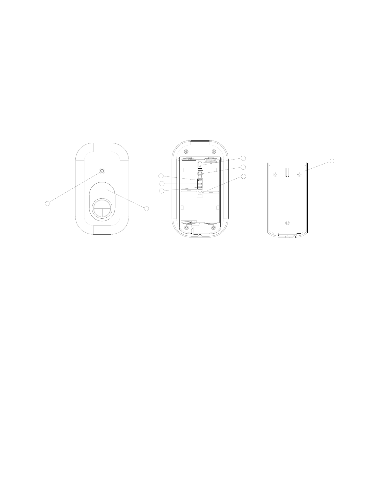
Siren & Strobe (SE802)
Strobe Light
Red & Green LED ( when both LEDs are on, the LED will be converted into orange color)
Tamper Switch
Learning Key
DC Jack
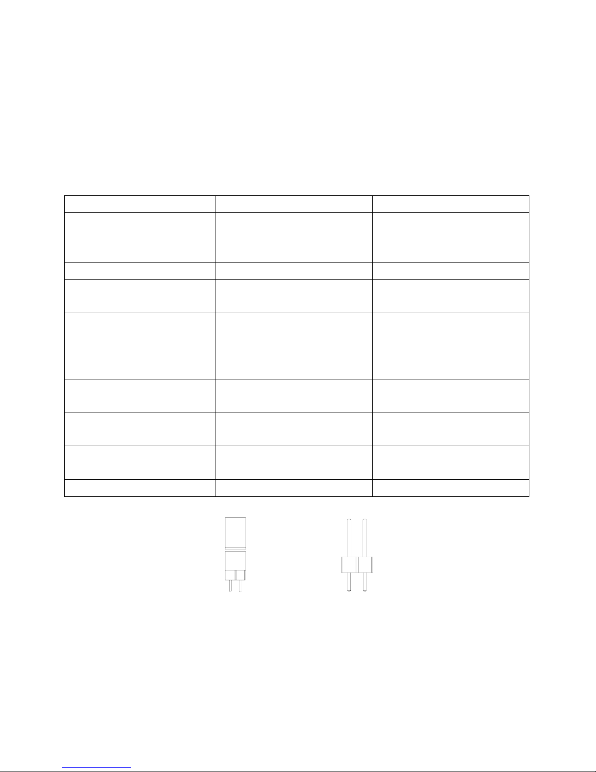
Two-Phase Sound Jumper Link
Anti-jamming Jumper Link
Tamper Jumper Link
Mounting Bracket
2
1
3
4
5
6
7
8
9
The kit includes one piece each of Solar-powered Wireless Pool Alarm, Siren & Strobe and Wireless
Keypad, all of which products have been designed to aid in the detection of unwanted intrusions into
unclosed above ground or in ground swimming pools. THE SOLAR-POWERED WIRELESS POOL
ALARM IS NOT A LIFE SAVING DEVICE. It should be used along with other safety equipment and
precautions. It is intended to provide an additional level of security to your swimming pool and/or spa. This
unit is not intended to replace any other safety consideration : adult supervision, lifeguards, fences, gates,
pool covers, locks, and so forth… And some devices may not detect gradual entry.
INTRODUCTION
The solar-powered pool alarm is an electronics device that, in armed mode, automatically sounds an
alarm when children or pet fall into your unsupervised pool. Entry into the above ground/in ground pool
will be detected by the unit’s electronics sensor, triggering a loud pulsating alarm.
Apart from it, the pool alarm is also compatible with our U-Net series, serving as a transceiver.
PACKAGE CONTENT
The solar-powered wireless pool alarm system is packaged in a gift box that minimizes the chance of
damage due to handling. The contents of the package include the following items:
3
Page 4

4
Item Qty
Solar-powered
wireless pool alarm
system(ST113)
Base
1
3
Initiation key 2
3
LR20 Alkaline Battery
4
3
Solar Panel with Ni-MH AA 6V
Rechargeable battery
1
3
Detachable tube
4
3
(φ4.7x30mm) Screw
4
3
Plastic wall plug 4
3
Siren & Strobe (SE802) 1
3
(φ3 x 18mm) Screw
3
3
Plastic wall plug 3
3
1.5V LR14 14A Size C 4
3
Wireless Keypad (SA802) 1
3
(φ3 x 18mm) Screw
2
3
Plastic wall plug
2
3
Operating instruction manual
1
3
SOLAR-POWERED WIRELESS POOL ALARM
INSTALLING THE POOL ALARM
There are four detachable tubes which can be jointed to a long tube. The length of tube depends on water
level in the pool. The distance from the bottom end of tube to water level must be greater than
24.5cm. (9.7 inch) A power drill and screwdrivers are needed for installation. Note: The unit may not
function properly if your pool’s water level is not maintained within the required levels of your device.
Page 5
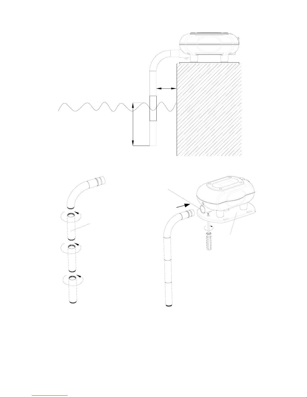
24.5cm
Under Water level
4.5cm
Tube
Base
Sensing Compartment
1. Locate the appropriate (plain and not very grassy) place to fix the unit on the top rail of the swimming
pool.
For the above ground pool, the unit must be installed at a height of 1.5m (59 inch) above the ground.
2. Joint the number of tubes according to actual water level as measured.
3. Insert the tube to the sensing compartment by fastening it through the base using the screw provided.
5
Page 6
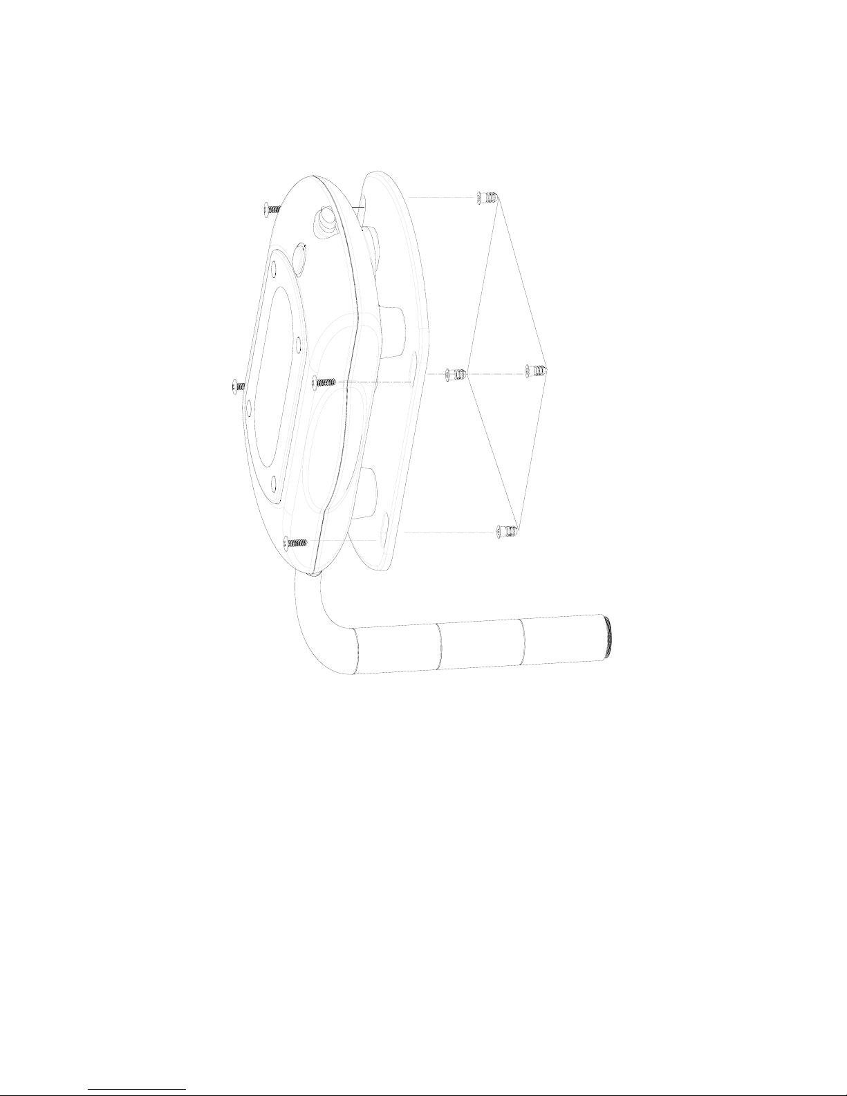
4. Use the base as a template to mark the position of four fixing holes. Drill four 30mm fixing hole and
fit the plastic wall plugs to the holes.
5. Aim the base to the place where four plastic wall plugs are situated. Fasten the base using the fixing
screws supplied.
6
1
8
.
2
C
M
(
7
.
1
6
I
N
C
H
)
1
4
.
6
C
M
(
5
.
7
5
I
N
C
H
)
LOADING THE BATTERY
Caution:
- use only the alkaline batteries as those provided.
- do not use out-of-date batteries (respect the expiry date),
- do not throw your old batteries in a dustbin : they contain toxic products, which are dangerous for the
environment. You must deposit them in vats envisaged for this purpose that you will find in great surfaces,
retailers, town halls...
Follow the below steps in sequence to load the batteries.
1. Remove four rubber stoppers and undo four fixing screws from the battery cover.
2. Open the battery cover and insert 4 x 13A LR20 1.5V alkaline batteries.
3. Plug the power supply cord to the DC jack.
Page 7
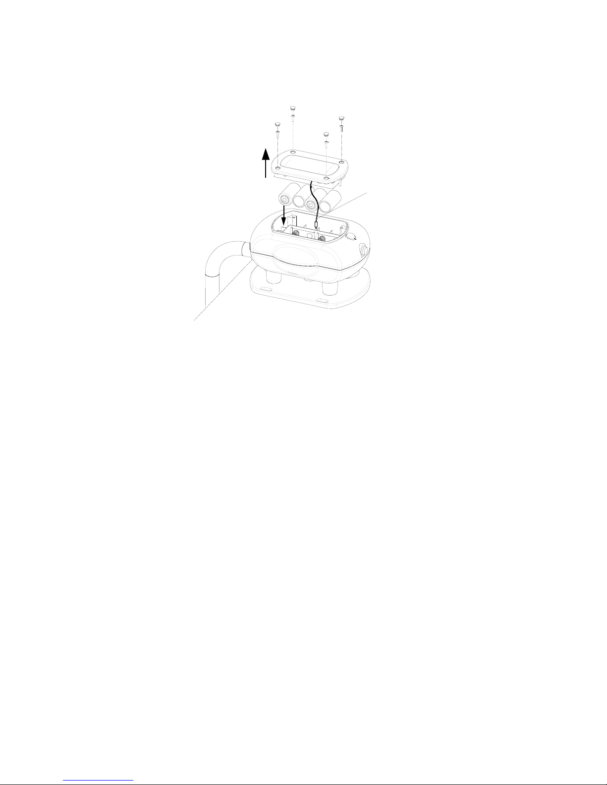
4. Replace the battery cover and fixing screws. Refit the rubber stoppers.
Note: Reverse battery cover cannot fit to the compartment.
Power Cord
DC Jack
WIRELESS KEYPAD
The Wireless Keypad is used to control the Pool Alarm by using a four digit Administrator password. The
Keypad is powered by 3 x AA 1.5V alkaline battery. Under normal operating conditions this will provide
an expected life in excess of 1 year. When the battery level falls below an unacceptable level, the
“Setting/Low Battery” LED on the front of the Keypad will flash 4 times when pressing any key. When this
occurs the batteries should be replaced as soon as possible.
POSITIONING THE KEYPAD
The Keypad should be mounted in a position close to the main entrance door so that the Administrator
password can be entered easily.
Ensure that the position selected for the Keypad is within the effective range of the solar-powered
wireless pool alarm.
Note: DO NOT fix the Keypad to metalwork or locate the unit within 1m of metalwork (i.e. radiators, water
pipes, etc) as this could affect the radio range of the Keypad.
INSTALLING AND CONFIGURING THE KEYPAD
1. Undo and remove the fixing screw from the bottom edge of the Keypad and remove the wall mounting
bracket.
7
Page 8
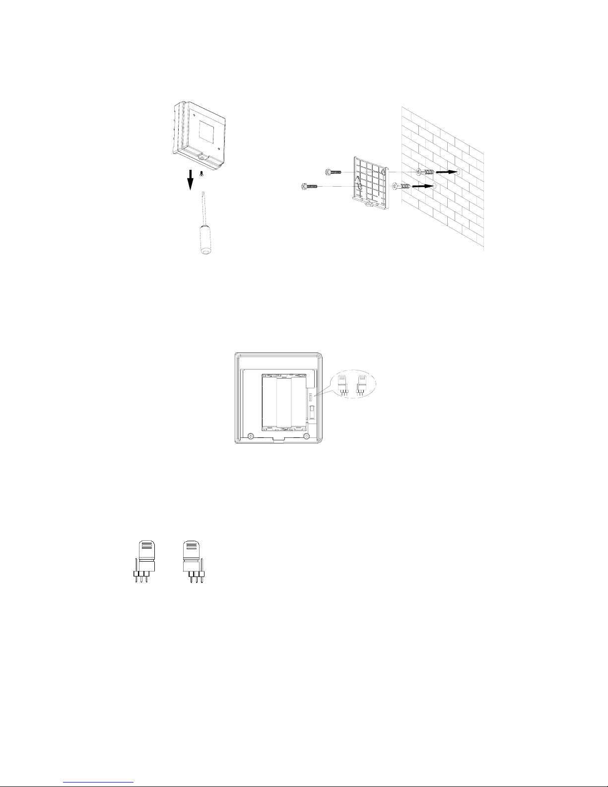
2. Using the mounting bracket as a template, mark the positions of the two fixing holes on the wall.
8
3. Fix the mounting bracket to the wall using the screws and wall plugs provided. Do not over-tighten
the fixing screws as this may distort or damage the mounting bracket.
4. There is one jumper link located above the battery compartment.
Jumper link J1: Reset to Factory default
If unfortunately you forget the Administrator password, reset the Administrator password to factory
default by proceeding with the following steps in sequence:
(1) Remove the batteries.
(2) Set the Jumper link J1 to off position as shown on Fig. a.
OFF ON
Fig. a Fig. b
(3) Refit the batteries. The keypad is reset properly by flashing back light 0~9 3 times.
123
123
(4) Set the Jumper link J1 to on position as shown on Fig. b.
5. Connect the 3 x AA alkaline batteries to the battery compartment.
6. Click the Keypad to the mounting bracket and screw the fixing screw. Do not over-tighten the fixing
screw.
Page 9
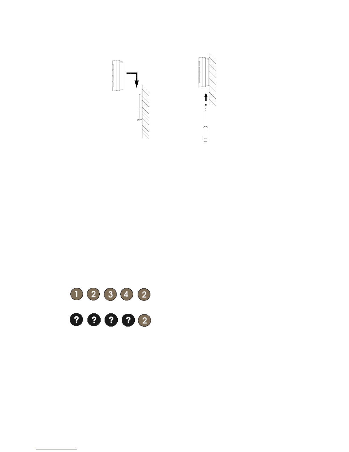
Note: The Keypad is supplied with a default Administrator password of: 1234. For security reasons, it is
recommended that this password is changed to another four digit number which only you and other users
of the system know.
Note: The Keypad has back light illumination facility. The back light of digit number 0~9 won’t be off until
5-second illumination duration expires each time when you press any key. Once transmission is
successful the back light of digit number 0~9 will extinguish. Failure to input any key more than 5 seconds
after each pressing will be treated as invalid input. The back light of digit number 0~9 will flash 3 times
as an indication.
CHANGING THE ADMINISTRATOR PASSWORD
Default Password: 1 2 3 4
To change the Administrator password, press the following keys in sequence:
(1) Press
Original Administrator password
(2) Enter
New Administrator password
SIREN & STROBE (SE802)
The Siren & Strobe serves as an auxiliary accessory to the Pool Alarm. When the Pool Alarm detects
unwanted intrusions into unclosed swimming pools, a full alarm condition will occur . Simultaneously , the
Siren & Strobe will initiate a full alarm condition as an intensive warning.
POSITIONING THE SIREN & STROBE
The Siren & Strobe is suitable for indoor use only. Ensure that the position selected for the Siren & Strobe
9
Page 10
is within the effective range of Pool Alarm.
INST ALLING AND CONFIGURING THE SIREN & STROBE
(1) Undo and remove the fixing screws from the mounting bracket.
(2) Place 4 x 1.5V alkaline LR14 batteries to the battery compartment. Ensure that correct polarity
of the batteries is inserted.
(3) Use the mounting bracket as a template to mark the positions of fixing holes on the wall.
(4) Fix the mounting bracket to the wall using the plastic wall plugs and fixing screws provided.
(5) According to the functions of the product layout, choose or justify the ones that suit you most.
Function Description
Red & Green LED Green LED: RF transmission
confirmation
Red LED: Warning indication
When red & green LED
illuminate simultaneously,
orange LED will be indicated
Strobe Light Warning indication
Learning Key Learning and cleaning out the
preset ID code
Tamper Switch A full alarm condition will be
initiated against the unit being
removed from the wall
Enable or disable this function
using tamper jumper link.
Jumper link fitted – enable
Jumper link removed - disable
Tamper Jumper Link Enable or disable this function Jumper link fitted – enable
Jumper link removed - disable
Anti-jamming Jumper Link Enable or disable this function Jumper link fitted – enable
Jumper link removed - disable
Two-phase Sound Jumper Link Sound volume selectable – 90 or
100 dB/1 meter
Jumper link fitted – 100 dB
Jumper link removed – 90 dB
DC Jack Use AC/DC adaptor
Jumper link fitted Jumper link removed
Enable Disable
(6) By releasing the tamper switch from being pressed if the tamper jumper link is enabled, the unit will
generate a full alarm condition by flashing its strobe light for about 6.5 minutes and red LED
illuminating shortly.
(7) If the battery level drops below unacceptable level, the red LED of the unit will flash shortly every 30
10
Page 11
seconds. When this occurs, the batteries should be replaced as soon as possible.
(8) In order to detect any attempts to illegally jam the radio channel used by your alarm system, a
special jamming detection function is incorporated into the unit. There are two types of jamming
detection.
a. If this feature is enabled, and the radio channel is jammed continuously for 30 seconds, when the
pool alarm is armed, the unit will emit a pre-alarm series of bleeps for 10 seconds. If the jamming
continues while 10 seconds of pre-alarm series of bleeps has elapsed, a full alarm condition will
occur for 30 seconds.
b. If the unit is jammed for more than three periods of 10 seconds in a 6.5 minute interval, this will
also generate a full alarm condition for 30 seconds.
Note: If the ambient environment of radio frequency is turbulence, set the anti-jamming jumper link
disabled by removing its jumper link.
OPERATI NG INSTRUCTIONS
Note:
Failure to press the start button by only turning the initiation key cannot operate the system.
The prerequisite to enter armed or auto mode is to keep pressing and holding the start button by
turning the initiation key as an effective operation.
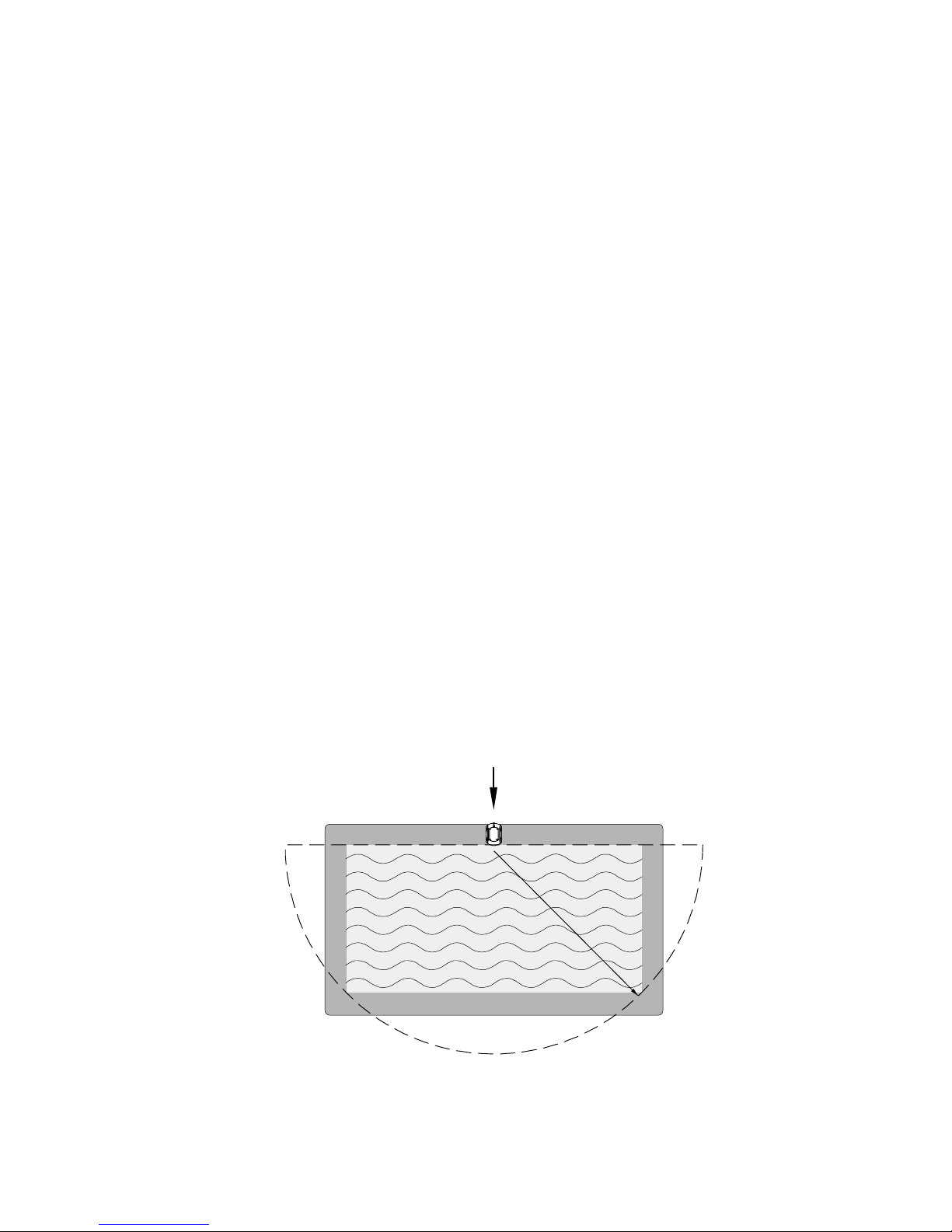
The Pool Alarm has been tested and certified in a 4m x 8m rectangular swimming pool. If your pool is
larger, or irregularly shaped, two units or more will be needed (Ask a help near your distributor).
In order to properly detect, the Pool Alarm must be installed at the middle of the longest side of your pool,
so that the effective detection coverage can be attained to the greatest extent. Using the Wireless Keyp ad
(SA802), of which mounting height is recommended at 1.7m above the ground, may control the Pool
Alarm remotely.
4m
8m
Pool Alarm
FIG. 6
11
Page 12
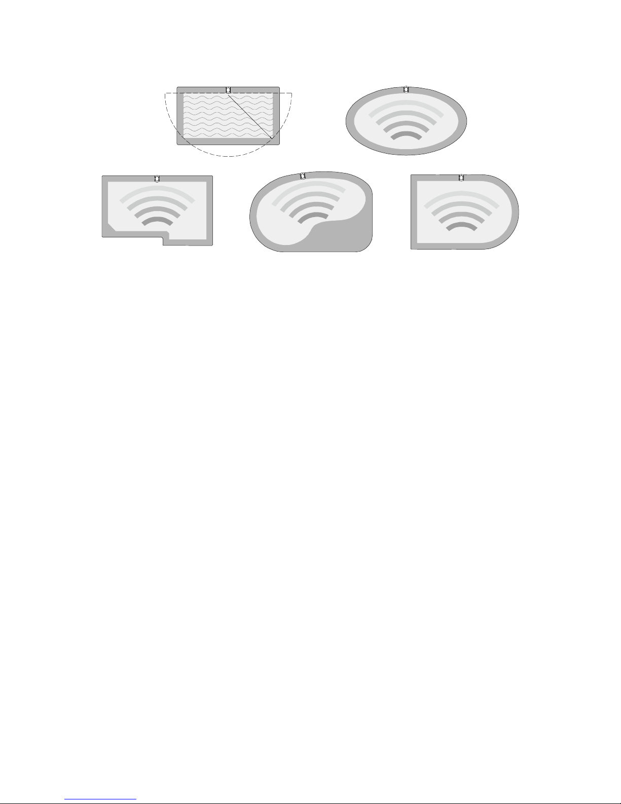
Typical examples of installation are shown below:
4m
8m
Be sure that the Pool Alarm is not installed next to any pool features (jets, water features, etc.) that
may cause disturbance.
Be sure that the Pool Alarm can be accessed easily.
INITIAL POWER-UP
When powering up initially , the Pool Alarm will enter the armed mode straight away. At this stage, you may
switch the Pool Alarm to the desired mode or wait for 30 seconds before throwing a 8 kgs (18 pounds)
object to the pool which will lead to a loud pulsating alarm sound both from the Pool Alarm and the Siren &
Strobe. It allows you to verify if the function of piercing alarm sound is working properly and to be sure if
the sound volume of Siren & Strobe can be heard inside your home.
TURNING ON THE POOL ALARM
1. Press and hold the start button on the Pool Alarm by turning the initiation key from OFF ON OFF
position. 3 bleeps can be heard as an acknowledgement after releasing the start button. The unit will
start detecting ambient environment for 8 – 14 minutes. The main purpose of it is to detect the wave
intensity of water action avoiding false alarming resulted from wave being caused by strong wind.
After completion of ambient environment detection, the Pool Alarm will bleep continuously for 3
seconds, confirming that the system has been armed.
12
Page 13
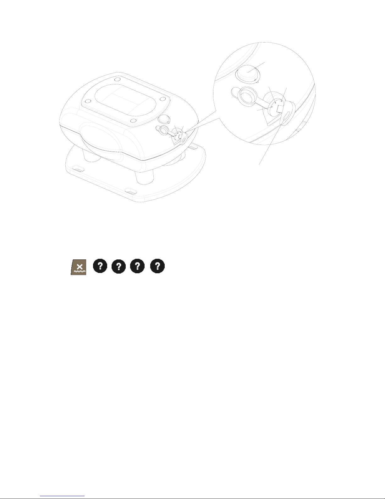
ON
Auto
OFF
Auto
OFF
ON
Start Button
Initiation Key
2. The Pool Alarm will instantly be monitoring your pool for an intrusion.
3. Using the Wireless Keypad:
Press
Administrator password
4. In case of unwanted intrusions into a swimming pool, the Pool Alarm will generate a full alarm
condition, while the auxiliary Siren & Strobe will alarm and flash for 30 seconds.
Note: If the Pool Alarm keeps on detecting the ambient environment without being armed properly,
possible reasons are:
a. After swimming, the water in the pool will rock or bounce up and down the pool wall for some time
depending on the size of the pool and the type of swimming activity. Before initiation the unit,
after swimming, the pool must be given time to calm. Time will vary (around 5-10 minutes); once
the pool water is no longer rocking up and down the pool wall, it is time to operate the unit.
b. On extremely windy days such bad weather, the unit cannot detect correctly.
TURNING OFF THE POOL ALARM
1.
Press and hold the start button by turning the initiation key either from OFF AUTO or from ON
OFF position. Do not release the start button until several bleeps are heard.
2. The Pool Alarm will bleep in response and enter the sleep mode, which means no automatic
activation will occur.
3. Using the Wireless Keypad:
13
Page 14
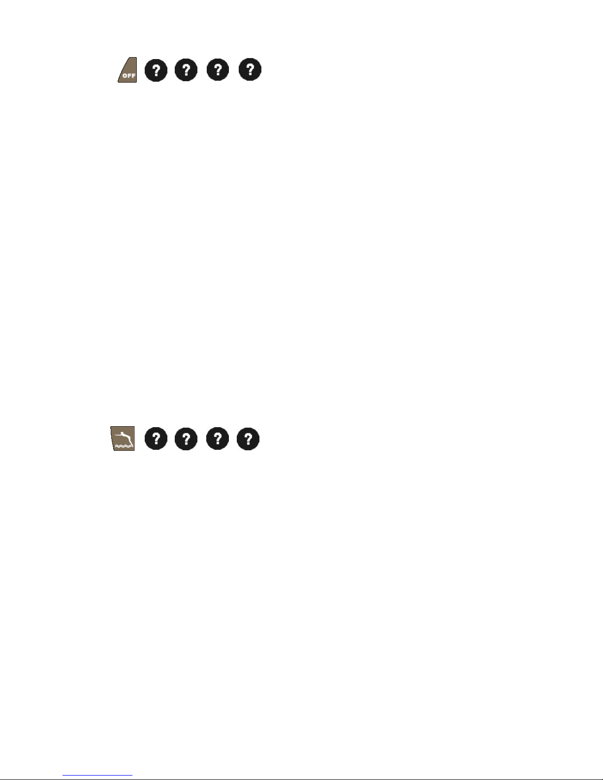
Press
14
A
dministrator password
AUTO MODE
1. Press and hold the start button by turning the initiation key from OFFAUTOOFF. 3 bleeps can be
heard as a confirmation after releasing the start button. The Pool Alarm will enter the auto mode.
Prior to entry into the pool, user may either turn off the unit or set the unit to auto mode. In auto mode,
the Pool Alarm won’t be triggered, but it will keep detecting the pool status. When no more wave
intensity of water action is detected, the mode of the system will be changed from auto to armed mode.
The minimum duration of auto mode is 30 minutes, starting from the unit being set at auto mode to
automatic change to armed mode.
In auto mode, the unit will keep extending its auto mode duration persistently as long as continuous
wave intensity of water action has been detected. As a result, the unit is likely to be set at auto mode for
a long time. When you have finished swimming, there are no waves on the pool. Press the start button
by turning the initiation key from OFFONOFF, then release the start button. Secondly, wait for the
elapse of ambient environment detection, so that the system will enter the armed mode.
2. Using the Wireless Keypad
Press
Administrator password
DISARMING THE ALARM SOUND
Upon detecting an unwanted intrusion into an unsupervised pool, the Pool Alarm and the Siren & Strobe
will sound immediately. To disarm the alarm sound, you must initiate a two-step operation. To achieve the
required alarm status, choose from one of the modes 1-3 below:
1. Turning off the Pool Alarm: Press and hold the st art button by turning the initiation key either from OFF
AUT O or from ON OFF position. Do not release the start button until several bleeps are heard.
The unit will bleep in response and then enter the sleep mode, which means no activation will occur.
2. Turning on the Pool Alarm: Press and hold the start button on the Pool Alarm by turning the initiation
key from OFF ON OFF position. 3 bleeps can be heard as an acknowledgement after releasing
the start button, the unit will start detecting ambient environment for 8 – 14 minute.
3. Auto mode: Press and hold the start button by turning the initiation key from OFFAUTOOFF. 3
bleeps can be heard as a confirmation after releasing the start button. The unit will enter the auto
mode.
Page 15

4. Using the Wireless Keypad
Press
Administrator password
After the Alarm sound is disarmed, the Pool Alarm will enter armed mode straight away.
LEARNING THE ID CODE
In order to prevent any unauthorized attempt to operate or disarm your system, you must configure your
system to accept radio signals only from your own system devices.
Firstly, have the Pool Alarm and the Siren & Strobe learned the ID code with each other. Secondly, have
the Pool Alarm and the Wireless Keypad learned the ID code. This may ensure correct operation among
the units. So, please follow strictly the sequences as mentioned below:
Pool Alarm and Siren & Strobe
1. Press and release the learning key on the Pool Alarm. The LED of start button will turn orange and
flash, which implies the unit enters the ID code learning mode.
2. Press the learning key on the Siren & Strobe for more than 3 seconds, during which continuous
bleeps will be underway while the green LED will be on.
3. If learning the ID code is successful, the Siren & Strobe will end up with a medium bleep and the
green LED will be changing from on to off, while the Pool Alarm will bleep once as a confirmation
without flashing the orange start button LED.
If failed, the Siren & Strobe will initiate three rapid bleeps as a notification.
Note: When putting the Siren & Strobe into use without any ID code being memorized or cleaning out
all of the preset ID codes, the orange LED will flash at 2 seconds interval and emit short bleep at about
10 seconds interval.
Pool Alarm and Wireless Keypad
1. Press and release the learning key on the Pool Alarm. The LED of start button will turn orange and
flash, which implies the unit enters the ID code learning mode.
2. Press on the Wireless Keypad
Administrator password
Enter
Note: During code learning period, all four function keys --
will be flashing simultaneously for 30 seconds.
15
Page 16
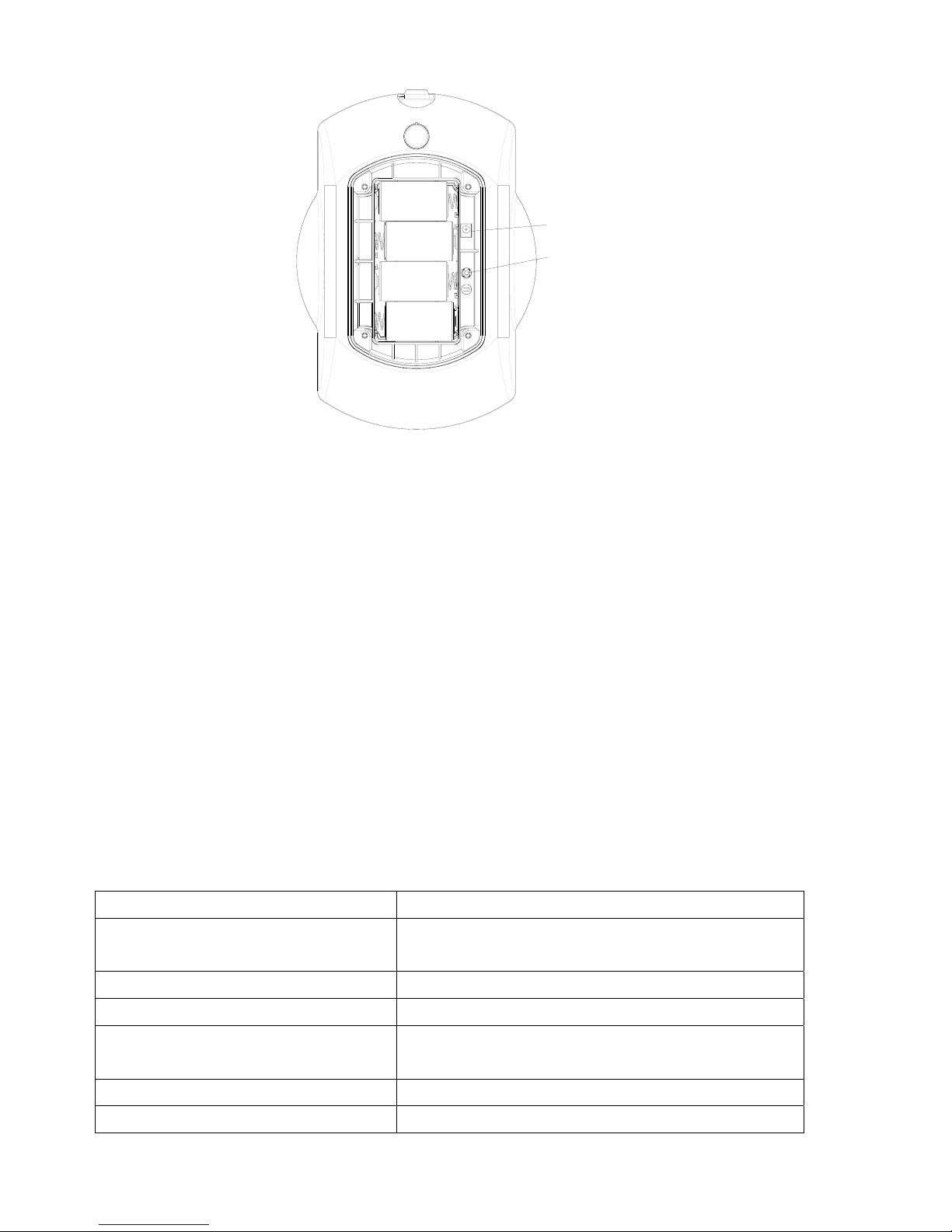
Learning Key
DC Jack
CLEANING OUT THE PRESET ID CODE
Pool Alarm
Press and hold the learning key on the Pool Alarm for more than 6 seconds will clean out the preset ID
code. 1 bleep can be heard as an acknowledgement.
Siren & Strobe
Press the learning key on the Siren & Strobe for more than 3 seconds and release. Within 30 seconds,
press the learning key again for more than 6 seconds, during which medium bleeps can be heard while
the green LED is on steadily . A long bleep with the green LED being off represent s the clearance of all of
the preset ID codes.
If failed, three rapid bleeps will be emitted from the Siren & Strobe as a notification.
QUICK GUIDELINE FOR LED INDICA TION AND BLEEP SOUND ON THE POOL
ALARM
Mode Status
System on / System off / Enter auto
mode
Continuous 3 short-bleep
Ambient environment detection Red flashing LED (0.1 second on, 0.5 second off)
Auto mode Green flashing LED (0.5 second on, 2.5 second off)
Enter armed mode Continuous bleep for 3 second with red illuminating
LED
Armed mode indication Red illuminating LED 0.1 second at 10 second interval
Strong wind indication Orange illuminating LED 0.1 second at 10 second
16
Page 17
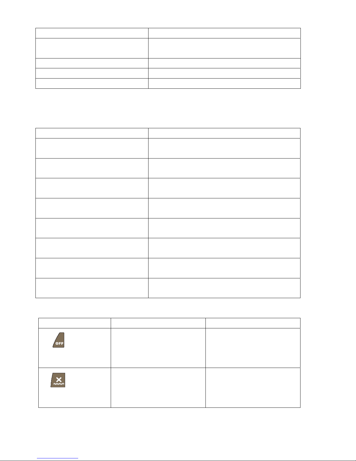
interval and bleep 0.1 second at 30 second interval
Low battery indication (under armed
mode)
Bleep 0.5 second and illuminating LED 0.5 second at
30 second interval
Keep pressing start button Orange illuminating LED
Learning the ID code period Orange slow flashing LED
Alarm activation Red illuminating LED
QUICK GUIDELINE FOR LED INDICATION AND BLEEP SOUND ON THE
SIREN & STROBE
Mode Status
Press learning key for more than 3
seconds to enter ID code learning mode
3 short-bleep and one medium bleep in the end
Green illuminating LED for 3 seconds
Learning the ID code period Intermittent short-bleep repeatedly
Green flashing LED repeatedly
Success in learning the ID code Medium bleep once
Green illuminating LED then off
Failure in learning the ID code 3 intermittent short-bleep
Green flashing LED 3 times
Press learning key again for 6 seconds
to clean out the preset ID code
Short bleep intermittently for 6 seconds
Green illuminating LED for 6 seconds
Success in cleaning out the preset ID
code
Long bleep once
Failure in cleaning out the preset ID
code
3 intermittent short-bleep
Green flashing LED 3 times
Empty ID code Short-bleep at 10 seconds interval repeatedly
Orange flashing LED repeatedly
QUICK GUIDELINE FOR LED INDICATION ON THE WIRELESS KEYPAD
Keypad Status Success Failure
Turning off the pool
alarm
back light 0~9 extinguish back light 0~9 flashing 3 times
Turning on the pool
alarm
back light 0~9 extinguish back light 0~9 flashing 3 times
17
Page 18

Auto mode
back light 0~9 extinguish back light 0~9 flashing 3 times
Disarming the alarm
sound
back light 0~9 extinguish back light 0~9 flashing 3 times
Pressing any key or
function key
back light 0~9 will be on
Learning the ID code
mode
back light 0~9 extinguish and 4
function keys illuminate
simultaneously for 1 second
back light 0~9 flashing 3 times
Warning:
Strong wind indication:
When the Pool Alarm is under armed mode detection, the wave pattern of water action may
be intensified resulted from strong wind or other interference. As a result, the Pool Alarm will be
converted to strong wind indication automatically. In the presence of strong winds, or very bad
weather, the Pool Alarm will not be able to carry out correct detection.
In armed mode detection with still wave pattern of water action, the Pool Alarm may be generated
a full alarm condition if it rains cats and dogs suddenly.
GENERAL SWIMMING POOL SAFETY GUIDELINES
- The safety of your children depends only on you! The risk is maximum when the children have less than
five years. The accident does not arrive only at the others! Be ready to face there!
- Supervise and act :
- the monitoring of the children must be brought closer and constant;
- designate only one person in charge for safety;
- reinforce the monitoring when there are several users in the swimming pool;
- learn how to swim with your children as soon as possible;
- wet nape of the neck, arm and legs before entering water;
- learn the gestures which save and especially those specific to the children;
- prohibit the dive or the jumps in the presence of young children;
- prohibit the sharp race and plays with the accesses of the swimming pool;
- do not authorize the access to the swimming pool without waistcoat or life jacket for a child not
knowing well to swim and not accompanied in water;
- do not leave toys in the vicinity and in the basin which is not monitored;
- permanently maintain a water limpid and healthy;
18
Page 19

- store the pesticides of water out of the range of the children;
- certain systems of stroke with against current do not allow the automatic reactivation of the system
of detection of immersion;
- certain robots of cleaning of plunger the robots type are incompatible with the systems of detection
of immersion;
- in order to prevent the access to the basin with the children of less than five years at the time of the
release of the signal of failure, to take all measurements necessary until repair.
- envisage:
- accessible telephone close to the basin not to leave your children without monitoring when you
telephone;
- buoy and pole near the basin;
- permanent information that the basin and its accesses are under electronic monitoring,
- only the change of the piles, batteries is authorized, and fuses, which must be done at the beginning of
season;
- in the event of accident:
- as soon as possible leave the child water;
- call help immediately and take the advice which will be given to you;
- replace the clothes wet by hot covers;
- to memorize and post close to the swimming pool the numbers of first aid:
- firemen: (18 for France);
- SAMU: (15 for France);
- poisons centre.
MAINTAI NING THE POOL ALARM
REPLACING THE BATTERIES
Replace the batteries whenever a low battery is indicated (see page 17 for a description of the low battery
indication). Be sure to turn the unit off whenever replacing the batteries.
SPECIAL CONSIDERATIONS DURING WINTER
The unit will not operate if the water in your pool becomes frozen. Additionally, allowing water to freeze
in the tube can damage the unit’s sensing mechanism.
19
Page 20

20
If your pool is located in an area where freezing normally occurs and you do not intend to maintain your
pool in a heated state throughout the winter season, you should remove the unit before freezing occurs.
Store the unit indoors and re-install when the water has thawed.
Be sure to remove the batteries from the unit when placing it in storage for a prolonged period.
Corrosion may occur if the batteries are left in the unit during storage.
PERIODIC TESTING
It is recommended that the unit be tested on quarter basis. Before testing, prepare the following test
simulator.
Fill a 2.5-gallon (11.3 liter ) water container with enough water to weigh approximately 18 pounds
( 8kg).
Tie a 6-foot (1.8meter ) length of rope to the container handle .
Follow the steps in sequence as mentioned below for testing:
Re-turning on the unit will initiate the system, of which operation is referred to page 12
“TURNING ON THE POOL ALARM”.
Hold the rope, and roll the test simulator into the pool.
Wait a moment for the unit to generate a full alarm condition.
If an alarm condition has not been occurred, refer to troubleshooting for resolution.
TROUBLESHOOTING
Symptom Possible Cause Recommendation
Upon power being connected,
the Pool Alarm cannot enter
armed mode directly
Batteries were not fitted
properly or reverse battery
polarity
Remove and refit the batteries
LED indicator not working on
the Pool Alarm
LR20 batteries or rechargeable
battery are not connected
properly
1. Remove and refit the batteries or
replace batteries
2. Call to local service for repair
Initiation key not working LR20 batteries or rechargeable
battery are not connected
properly
1. Remove and refit the batteries or
replace batteries
2. Send the unit for repair
Low battery indication Run out of battery power Replace LR20 batteries
Wireless keypad (SA802)
cannot control solar-powered
wireless pool alarm
Failure in learning the ID code 1. Resume ID code learning
process
2. Clean out the preset ID code and
resume ID code learning process
Page 21

21
Abnormal activation Tube is not saturated by
enough water level
1. Reallocate the mounting position
of the unit
2. Add an extra tube
3. Add much water to the pool
thus enhancing water level
Did not fit the batteries or
insufficient battery level
Check if the batteries are fitted or
replace new batteries
LED indicator not working on
the Siren & Strobe
The unit is out of order Send the unit for repair, do not open
up the casing of the unit
Failed to learn the ID code
between the Pool Alarm and
Siren & Strobe
Check if the initial installation of the
Pool Alarm had been cleaned out the
preset ID code. According to the
operating manual of Pool Alarm,
resume the ID code learning
procedure.
Siren & Strobe’s LED indicator
working, but cannot learn the
ID code or cannot control
Interfered by radio frequency.
Someone might transmit
868.3MHz adjacently.
Wait for a while to retry
Failed to learn the ID code
between the Pool Alarm and
Siren & Strobe
Check if the initial installation of the
Pool Alarm had been cleaned out the
preset ID code. According to the
operating manual of Pool Alarm,
resume the ID code learning
procedure.
Siren & Strobe cannot be
controlled by the Pool Alarm
Too far distance Relocate mounting location between
the Pool Alarm and Siren & Strobe
Replace a new battery
Press key on the Keypad, LED
no reaction
Remove and refit the battery with
correct polarity
Proceed with learning the ID code
The connected wireless pool
alarm not working
Ensure correct operation of learning
the ID code
Forgot password on the
Keypad
Reset to the factory default setting
Page 22
22
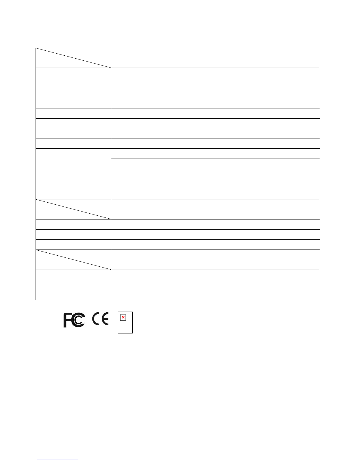
SPECIFICATIONS
Model No.
Item
ST113 Solar-powered Wireless Pool Alarm
Siren Twin piezo siren
Siren Output 110 dB / 1 meter
Effective Pool Alarm
Dimension
4m x 8m (157.5 inch x 315 inch), subject to Min. 6 kgs (13 pounds) object
being fallen
Operating Power 6 VDC
Power Supply Solar panel with Ni-MH AA 6V rechargeable battery and 1.5V x 4 alkaline
battery LR20
Frequency 923 MHz Transceiver (USA)
Above ground pool at 1.5m height above the ground : Up to 90m Working Range
In ground pool: Up to 70m
Protection Degree IPX5
Operating Temperature
0°C ~ 45°C
Safety NF P90-307A1(France) / CE/FCC/ASTM (USA)
Model No.
Item
SA802 Wireless Keypad
Battery
AA 1.5V alkaline battery x 3
Frequency
923 MHz
Communication Range Up to 100m (3937 inch) in open space
Model No.
Item
SE802 Siren & Strobe
Battery or Adapter 6VDC
Frequency 923 MHz
Communication Range Up to 100m (3937 inch) in open space
*Specifications are subject to change without prior notice.
ASTM
A501110701R
Federal Communication Commission Interference Statement
This equipment has been tested and found to comply with the limits for a Class B digital device, pursuant to Part 15
of the FCC Rules. These limits are designed to provide reasonable protection against harmful interference in a
residential installation. This equipment generates, uses and can radiate radio frequency energy and, if not installed
and used in accordance with the instructions, may cause harmful interference to radio communications. However,
there is no guarantee that interference will not occur in a particular installation. If this equipment does cause
harmful interference to radio or television reception, which can be determined by turning the equipment off and on,
the user is encouraged to try to correct the interference by one of the following measures:
- Reorient or relocate the receiving antenna.
- Increase the separation between the equipment and receiver.
- Connect the equipment into an outlet on a circuit different from that to which the receiver is connected.
- Consult the dealer or an experienced radio/TV technician for help.
Page 23

23
This device complies with Part 15 of the FCC Rules. Operation is subject to the following two conditions: (1) This
device may not cause harmful interference, and (2) this device must accept any interference received, including
interference that may cause undesired operation.
This transmitter must not be co-located or operating in conjunction with any other antenna or transmitter.
This equipment should be installed and operated with a minimum distance of 20 centimeters between the radiator
and your body.
Any changes or modifications (including the antennas) made to this device that are not expressly approved by the
manufacturer may void the user’s authority to operate the equipment.
FCC Caution: Any changes or modifications not expressly approved by the party responsible for compliance could
void the user's authority to operate this equipment.
IMPORTANT NOTE:
FCC Radiation Exposure Statement:
This equipment complies with FCC radiation exposure limits set forth for an uncontrolled environment. End users
must follow the specific operating instructions for satisfying RF exposure compliance.
This transmitter must not be co-located or operating in conjunction with any other antenna or transmitter.
WARNING:
Do not dispose of electrical appliances as unsorted municipal waste, use separate collection facilities.
Contact your local government for information regarding the collection systems available.
If electrical appliances are disposed of in landfills or dumps, hazardous substances can leak into the groundwater
and get into the food chain, damaging your health and well-being.
When replacing old appliances with new once, the retailer is legally obligated to take back your old appliance for
disposal at least for free of charge.
WARRANTY
1) Warranty period:
2 years as from the date of purchase (the sales slip or the purchase invoice will have to be provided for
the execution of the guarantee).
Please complete the Exhibit-A form and send it back for your product registration.
2) Conditions of the guarantee:
- Without damage of the legal guarantee, the products are recognized provided in good operating
condition, without apparent defect and are guaranteed if they are used according to the instructions
contained in the Instruction manual.
- The guarantee comprises the following services:
A helpline : help with the installation, parameter setting, brought into service and resolution of
breakdowns not requiring the return of the material in workshop
RMA (Repair in workshop) by repairing or standard exchange of the returned defects items.
Page 24

24
- The guarantee does not cover:
transport charges as well as the expenses related with an intervention in residence.
Claws, stripes, glares and/or imprint etc... not noted with the delivery
Breakable accessories except manufacturing defect recognized by our engineering departments,
Batteries
- The contractual guarantee does not apply in the event of:
Not respect of the instructions of installation;
Abnormal Use of the products like use or incorrect connection;
Damage due to shocks of any origin;
Damage due to fire, sets fire to, penetration of liquid or solid substances;
Damage due to an overload, the lightning;
Damage due to a modification or intervention carried out by any unauthorized person by HZE;
Damage due to a natural disaster, floods or vandalism.
CONTACT US
Please feel free to write or call us with your comments or questions at the address below.
Everspring Tech USA, INC
3200 Wilshire Blvd. South Tower, STE# 1730
Los Angeles, CA. 90010
Tel: (626) 698-1898, Fax: (626) 956-0600
Email: [email protected]
EXHIBIT –A–
PLEASE TAKE THE TIME TO COMPLETE YOUR DETAILS BELOW AND RETURN
With a proof of buying (Invoice or bill)
To :
Via email :
Via courrier :
3200 Wilshire Blvd. South Tower, STE# 1730
Los Angeles, CA. 90010
Tel: (626) 698-1898, Fax: (626) 956-0600
Page 25
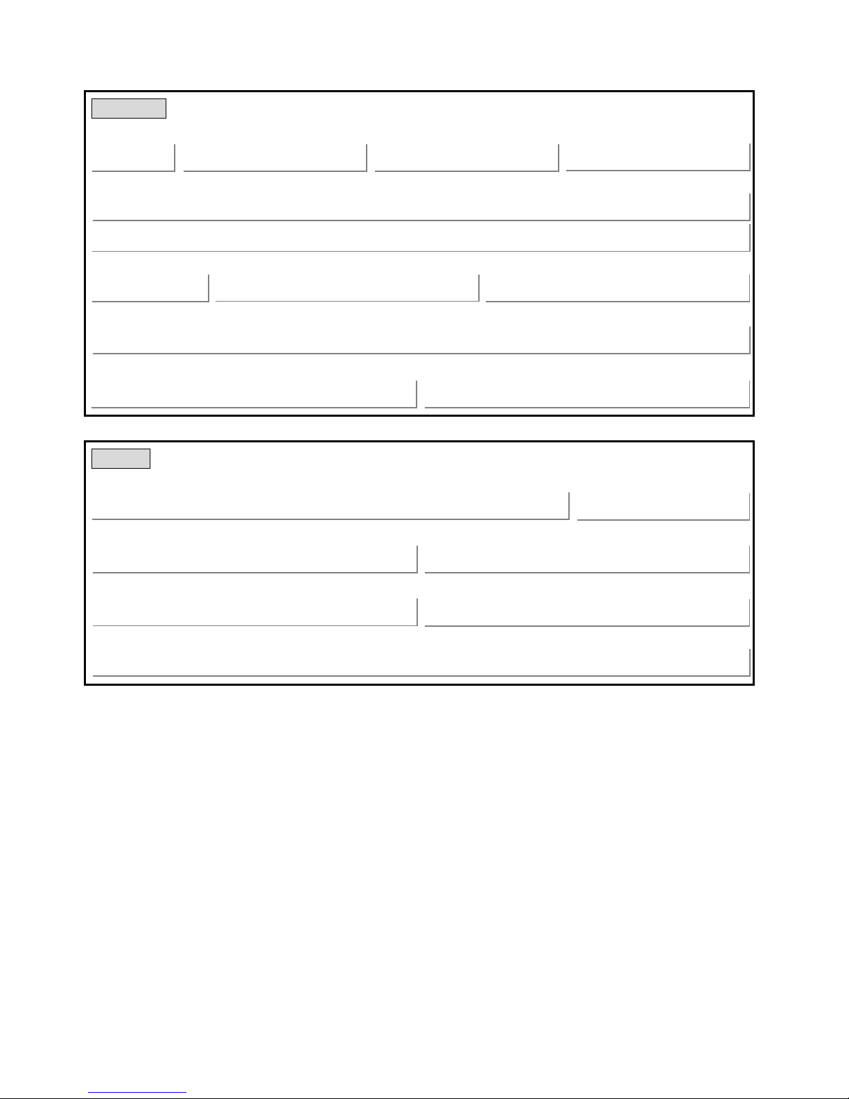
Customer
Title (Mr/Ms) First Name Middle Initial Last Name
Address
25
Zip Code City Country
Email
Telephone (area code) Fax (area code)
Retailer
Name Date of purchase
City Country
Model No S/N
P/N
(
) -
(
)
-
 Loading...