

Page 1
SP817 MOTION DETECTOR
The SP817 Motion Detector is a Z-Wave
TM
enabled device which is fully compatible with any Z-WaveTM
enabled network. The device can be set up in a Z-Wave network to communicate directly with other end
devices such as lighting controllers, or to report directly to a Z-Wave controller (usually a gateway).
This product supports the S2 security protocol that uses encrypted Z-Wave Plus messages to
communicate to other security-enabled Z-Wave Plus products. A security-enabled Z-Wave Plus
Controller must be used in order to fully utilize the security features of this product.
The Motion Detector is designed with two detecting sensors, Passive Infra-Red (PIR) sensor and light
sensor, in order to fulfill the purpose of security and home automation. When the detector is cooperated
with security appliances, it is acting as a security device by detecting changes in infra-red radiation levels.
If a person moves within or across the device field of vision, a trigger radio signal will be transmitted to
cause full alarm condition in order to frighten intruders away. Alternatively, when the detector is worked
with home automation appliances, the detector can be set to perform the role of home automation device
by detecting both changes in infra-red radiation levels and percentage of lux levels. Once night falls,
the percentage of ambient illumination is lower than preset value. If a person moves within or across the
device field of vision, a trigger radio signal will be transmitted so as to turn on the connected lightings for
better illumination.
The PIR Detector adopts a CR123 3.0V Lithium battery which under normal conditions will have typical
life in excess of 1 year. When the battery level drops to an unacceptable level,,the detector will emit
Battery report to the Z-Wave controller. When this occurs the batteries should be replaced as soon as
possible.
Product Overview
Adding to Z-Wave
TM
Network
Auto Inclusion
The detector supports Auto Inclusion feature where it will automatically enter Inclusion mode when first
powered up after a factory reset.
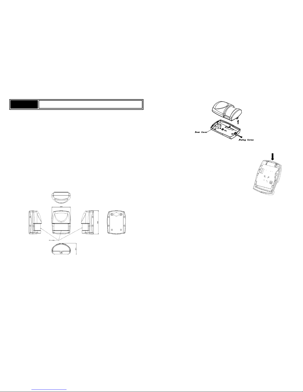
1. Use a screwdriver to detach the rear cover.
2. Put a Z-Wave Controller into inclusion mode.
3. Insert 1 CR123 3V batteries to the battery compartment with
the correct polarity. The LED on the device should turns ON..
4. The Inclusion process should be completed when the LED stops blinking.
5. Do not refit the rear cover yet.
Note: If Auto Inclusion fails, refer to the Troubleshooting section regarding Manual Inclusion.
Testing
Warm-Up
It will take approximately 2 minutes to warm up for the detector after battery is inserted. During this period
the LED behind the lens will turn on When the red LED turns off, it implies warm-up procedure is
completed and the detector is ready for detection.
- This will not affect the Inclusion/Exclusion process.
- After removing batteries, wait for 5 seconds to refit batteries.
Quick Test
1. With the tamper switch not being pressed after inclusion,,the unit will enters Test mode to allow the
user to test the device before it is mounted on the wall.
2. During Test mode, if movement is detected, the LED on the detector will light up once implying the
unit is working properly, and retrigger time is about 5 sec.
3. To exit the Test mode, simply press the Tamper switch for more than 10 seconds to enter Normal
mode.
4. During normal mode, when PIR is triggered, the red LED will not light up and retrigger time is based
on set up value.
Page 2
Mounting the Detector
Choosing the location
The PIR Detector is suitable for mounting in dry interior locations only.
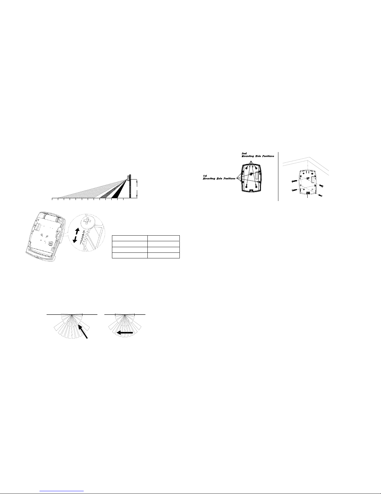
The recommended position for a PIR Detector is in the corner of a room mounted at a height between 1.8
and 2m. At this height, the detector will have a maximum range of up to 9m with a field of view of 110°,
subject to the position for the PCB being set in 5. (FIGURE 1&2) The position of the PCB inside the PIR
can be set to 5 different positions to adjust the range of the detector. Setting the PCB in position 3 will
reduce the range to 6m approximately, with position 1 providing a range of 3m approximately. The
recommended position setting for the PCB is in position 5.
FIGURE 1
PCB Position Range
1 3m
3 6m
5 9m
FIGURE 2
When considering and deciding upon the mounting position for the detector the following points should
be considered to ensure trouble free operation:
1. Do not locate the detector facing a window or where it is exposed to or facing direct sunlight. PIR
Detectors are not suitable for use in conservatories.
2. Do not locate the detector where it is exposed to ventilators.
3. Do not locate the detector directly above a heat source, (e.g. fire, radiator, boiler, etc).
4. Where possible, mount the detector in the corner of the room so that the logical path of an intruder
would cut across the fan detection pattern. PIR detectors respond more effectively to movement
across the device than to movement directly towards it. (FIGURE 3)
Less Sensitive More Sensitive
FIGURE 3
5. Do not locate the detector in a position where it is subject to excessive vibration.
6. Ensure that the position selected for the PIR detector is within effective range of the system, (refer
to System Installation and Operating Manual).
Note: When the system is armed, household pets should not be allowed into an area protected by a
PIR detector as their movement would trigger the PIR and generate an alarm.
Installation
1. Carefully drill out the required mounting holes in the rear cover using 3mm drill according to whether
the unit is being mounted in a corner or against a flat wall.
Note: Using 1
st
mounting hole to fulfill corner mounting installation, while 2nd mounting hole for flat
wall installation. (FIGURE 4a & 4b)
FIGURE 4a FIGURE 4b
3. Using the rear cover as a template, mark the positions of the fixing holes on the wall.
4. Fix the rear cover to the wall using the two 18mm No.4 screws and 25mm wall plugs, (a 5mm hole
will be required for the wall plugs). Do not over-tighten the fixing screws as this may distort or
damage the cover.
5. Configure the detector as described below. Remember that on initial installation that the device
needs to be tested.
6. Check that the detector PCB is located and set in the correct position to provide the required
detection range. To adjust the PCB position, simply slide it up or down ensuring that the location
legs are aligned with the required position number marked on the board.
7. To refit the detector to the rear cover and locate the clips in the top edge into the rear cover. Push
the lower edge of the detector into place and refit the fixing screw in the bottom edge of the detector
to secure in position. Do not over-tighten the fixing screws as this may damage the casing.
8. By walking into a protected area within coverage of 110 degrees, the detector will now be triggered
each time the detector senses movement. The associated appliances will be activated. For
example, siren will be sounded or indication of movement detection will be shown on the controller.
It implies that the unit is working properly.
Programming
Z-Wave Group
The detector supports either one of two Z-Wave Association Groups:
Group 1: Association with 1 Controller node.
Group 2: Association with 4 nodes (i.e. end devices such as smart plugs and other lighting controllers).
This allows the detector to transfer commands directly to end devices without the participation of the
controller. This has the effect that when the detector triggers, all devices associated with detector will be
operated.
Group 1 commands:
When the unit is powered up and was already a part of a Z-Wave network, the unit will send a
Notification Report to the node in Group 1.
When the detector senses a movement, the unit will send a Notification Report to the nodes of Group
1. Once the movement is stopped, a Notification Report will be sent again to Group 1.
Upon d etector status being changed, the unit will check its battery status simultaneously. When the
battery level of the unit drops to an unacceptable level, the unit will emit Battery report to the nodes of
Group 1.
When performing Factory Reset the unit will send Device Reset Locally Notification to the node of
Group1.
1
23
45
6
7
89101112
0
13
2M
Corner mounting
Page 3
Group 2 commands:
When the detector is triggered, the unit will send BASIC_SET command which contains a value to
the nodes of Group 2.
Z-Wave Plus Info
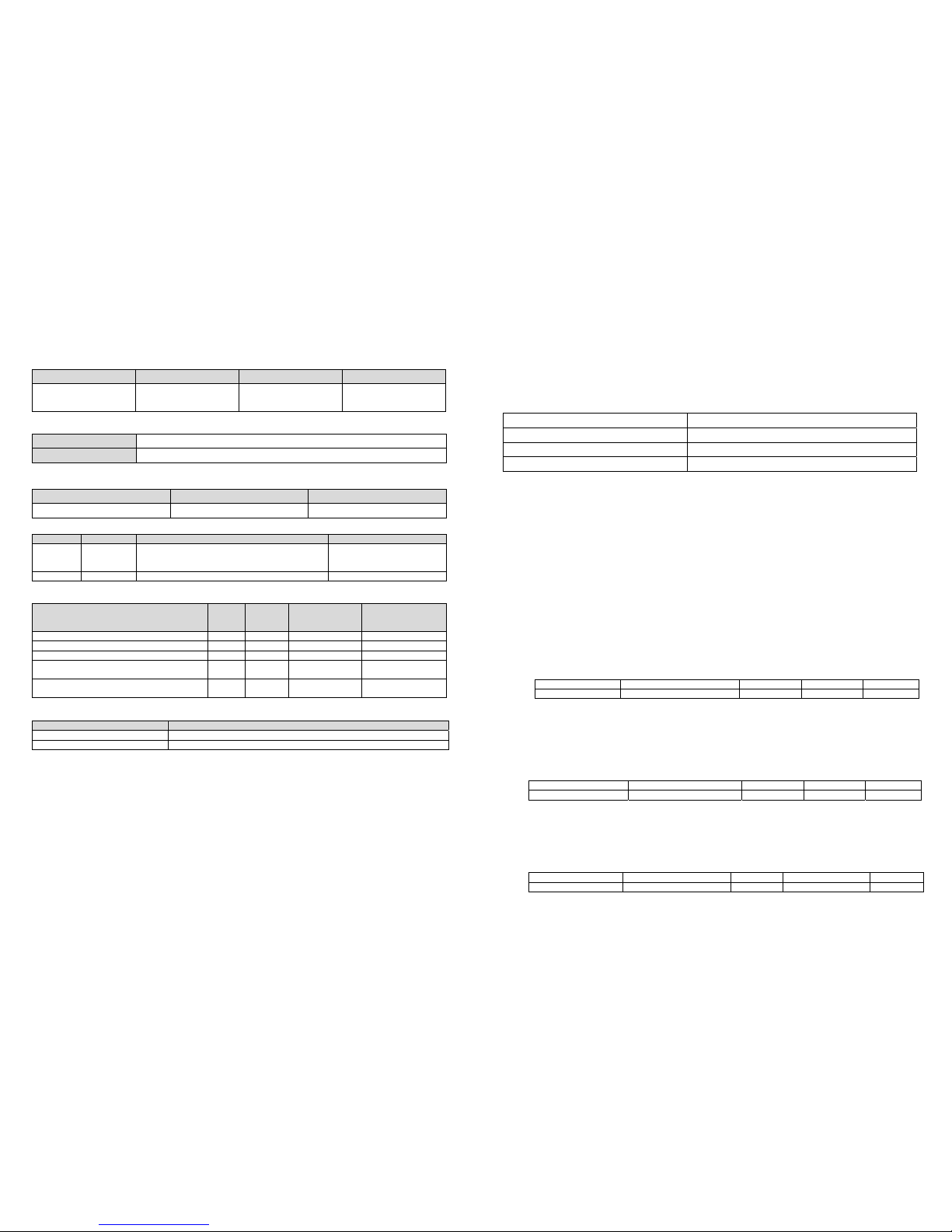
Role Type Node Type Installer Icon User Icon
Slave Sleeping report Z-Wave Plus node Sensor Notification
Device Type (Home
Securit
y)
Sensor Notification
Device Type (Home
Securit
y)
Version
Protocol Library 3 (Slave_Enhance_232_Library)
Protocol Version 4.3D ( 6.71.01)
Manufacturer
Manufacturer ID Product Type Product ID
0x0060 0x0001 0x0006
AGI (Association Group Information) T able
Group Profile Command Class & Command (List) N bytes Group Name(UTF-8
)
1 General
Battery Report
Notification Report
Device Reset Locally Notification
Lifeline
2 Control Basic Set PIR Control
Notification
Event Type Event
Event
Parameters
Length
Event Parameters
The power is applied for the first time 0x08 0x01 0x00
PIR Trigger ON 0x07 0x08 0x00
PIR Trigger OFF 0x07 0x00 0x01 0x08
Tamper switch being press more than 10
seconds
0x07 0x00 0x01 0x03
Tamper switch being press more than 10
seconds and released
0x07 0x03 0x01
Battery
Battery Report (value) Description
20~100 Battery Level (%)
0xFF Low Battery
Command Classes
The module supports Command Classes including…
COMMAND_CLASS_ZWAVEPLUS_INFO_V2
COMMAND_CLASS_ASSOCIATION_V2
*
COMMAND_CLASS_ASSOCIATION_GRP_INFO*
COMMAND_CLASS_TRANSPORT_SERVICE_V2
COMMAND_CLASS_VERSION_V2
*
COMMAND_CLASS_MANUFACTURER_SPECIFIC_V2
*
COMMAND_CLASS_DEVICE_RESET_LOCALLY
*
COMMAND_CLASS_POWERLEVEL
*
COMMAND_CLASS_SECURITY
COMMAND_CLASS_SECURITY_2
COMMAND_CLASS_SUPERVISION
*
COMMAND_CLASS_FIRMWARE_UPDATE_MD_V4
*
COMMAND_CLASS_BATTERY*
COMMAND_CLASS_WAKE_UP_V2
*
COMMAND_CLASS_NOTIFICATION_V4
*
COMMAND_CLASS_CONFIGURATION*
*Items marked an asterisk are secure command classes.
Wakeup Command Class
After it has been included into a Z-Wave network, the detector will go to sleep but will send a Wakeup
Notification Command periodically at preset period to the controller. The Motion detector will stay awake
for 10 seconds at least and then go back to sleep to conserve battery life.
The time interval between Wakeup Notification Commands can be set in the Wakeup Command Class
based on the range values below:
Minimum Wake Up Interval 600s (10 minutes)
Maximum Wake Up Interval 86400s (1 day)
Default Wake Up Interval 14400s (4 hours)
Wake Up Interval Step Seconds 600s (10minutes)
Z-Wave’s Configuration
The following information is for someone that has some experience in setting up a Z-Wave system or
someone that has computer software running a Z-Wave controller. Please get familiar with software of
Z-Wave controller before getting started.
To save power consumption for the battery, RF power of SP817 is in off mode ordinarily. Pls press
T amper switch once to on the RF power for 30 sec. in order to start function set up, and the user can see
the LED start lighting up shortly every sec.. If set up is not finished within 30 sec., please press Tamper
switch one more time to continue the set up.
1-1 Basic Set Level
When Basic Set Command is sent where contains a value, the receiver will take it for
consideration; for instance, if a lamp module is received the Basic Set command of which value is
decisive as to how bright of dim level of lamp module shall be.
Example:
1-99: ON (Binary Switch Device)
Dim Level (Multilevel Switch Device)
Function Parameter Number Size Ran
g
e Default
Basic Set level 1 1 1 ~99 99
1. Sensitivity Level (PIR sensor only)
In order to provide a best efficiency of the detector, it is recommended to test the detector with
movements from a farthest end of the coverage area at first time of use. If movements cannot be
detected sensitively, simply adjust the sensitivity level with Configuration Parameter #3. This
parameter can be configured with the value of 1 through 10, where 1 means low sensitivity and 10
means highest sensitivity.
Function Parameter Number Size Ran
g
e Default
Sensitivity Level 3 1 1~10 6
2. Re-trigger Interval Setting (PIR sensor only)
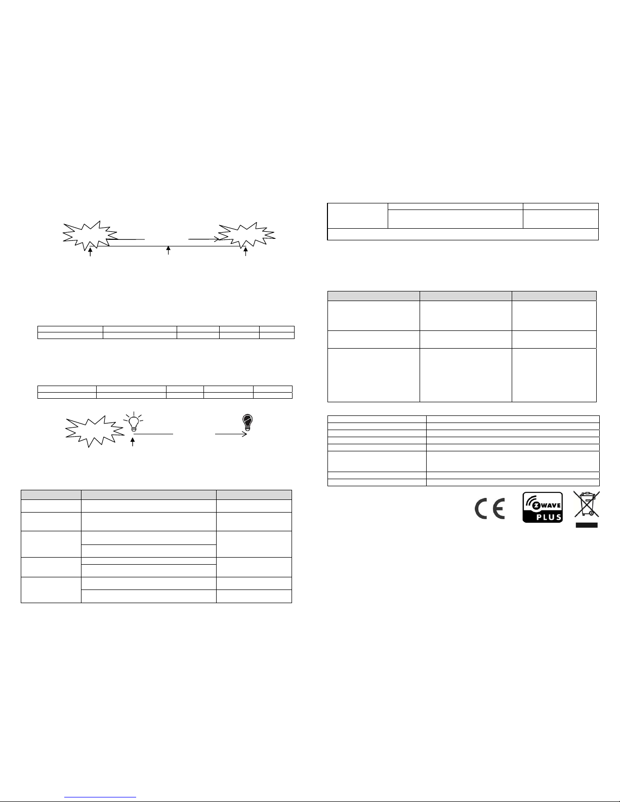
The Configuration parameter that can be used to adjust the interval of being re-triggered after the
detector has been triggered as Configuration Parameter #4. No response will be made du ring
this interval if a movement is presented. The time interval can be set between 5 secs to 3600
secs.
Function Parameter Number Size Ran
g
e Default
Re-trigger Interval 4 2 5~3600(sec) 180
Page 4
3. Lux Level
The user can set a detecting percentage of lux level which determines when the light sensor will
be activated. If percentage of lux level of ambient illumination falls below this percentage, and a
person moves across or within the protected area, the detector will emit Z-Wave ON Command
(i.e. Basic Set Command (Value = Basic Set Level)) to controller and activate connected modules
and lighting. Percentage can be set between 1% to 100%.
Function Parameter Number Size Ran
g
e Default
Lux Level 5 1 1~100 % 20
4. On-Off Duration
The function of on-off duration setting will be useful if the detector is connected with a module or
lighting. The duration determines how long the module/lighting should stay ON. For instance,
Lamp Module turns off 100 secs after it has been turned on. This parameter can be configured
with the value of 5 through 3600, where 5 means 5 second delay and 3600 means 3600 seconds
of delay.
Function Parameter Number Size Ran
g
e Default
On-Off Duration 6 2 5~3600(sec
)
15
Troubleshooting
The table below lists the several steps involved when adding or removing the detector from the Z-Wave
network.
Action/Status Description LED indication
No node ID
The Z-Wave Controller does not allocate a node
ID to the unit.
2-second on, 2-second off
For 2 minutes
Auto Inclusion
The power is applied for the first time and no node
ID has been stored in the module, or after
executin
g
reset.
Manual Inclusion
1. Put the Z-Wave Controller into
inclusion mode.
2. Press the tamper switch 3 times within 1.5
seconds to put the unit into inclusion mode.
Exclusion
1. Put the Z-Wave Controller into exclusion mode.
2. Press the tamper switch 3 times within 1.5
seconds to put the unit into exclusion mode.
Factory Reset
(This procedure
should only be used
when the controller
1. Press the tamper switch 3 times within 1.5
seconds to
p
ut the unit into exclusion mode.
2. Within 1 second of step 1, press the tamper
switch a
g
ain and hold until LED is off (about 5
is inoperable.) seconds).
3. Node ID is excluded. The device reverts to
factory default state and will be in
auto-inclusion mode for 4 minutes.
2-second on, 2-second off
For 2 minutes
Failed or successful results in including/excluding the ID can be viewed on the Z-Wave Controller.
Note: If you are connecting this unit to a Z-wave Controller that utilizes the S2 security protocol, you may
be asked to enter a 5 digit Device Specific Key (DSK) that is unique to each unit by your controller. This
can be found in one of two places:
- on the QR code label on the back of the unit
- on the insert card inside the packaging
Table below lists typical problems encountered:
Symptom Possible Cause Recommendation
Cannot carry out inclusion and
association
1. Run out of battery powe
r
2. Check if reverse battery
polarity
3. Check if the detector is out
of orde
r
1. Replace a new battery
2. Refit the battery with
correct polarity
3. Ensure the detector is
workin
g prop
erly
Cannot control the connected
modules
1. Run out of battery powe
r
2. Check if the detector is out
of orde
r
1. Replace a new battery
2. Ensure the detector is
working properly
The detector not working 1. Run out of battery
power
2. Check if the mounting
location is proper
3. Check if the detector is
mounted above a radiator
or heater
4. Check if the detector is out
of orde
r
1. Replace a new battery
2. Reposition its mounting
location
3. Remove the source of
interference or
reposition its mounting
location
4. Ensure the detector is
workin
g prop
erly
Specifications
Battery CR123 3.0V 1700mAh Lithium Battery
Battery Life 1 year*
Range Up to 100 meters line of sight
Warm Up Time About 2 minutes
PIR Detection Coverage Up to 10m x 110° (at 1.8m mounting height & 25°C)
Operating Frequency
EU: 868.42HMz
US: 908.42 MHz
JP: 922.5MHz
FCC ID FU5SP817
IC 23210-SP817
Specifications are subject to change without notice
*measured at 10 triggers per day
Federal Communication Commission Interference Statement
This device complies with Part 15 of the FCC Rules. Operation is subject to the following two
conditions: (1) This device may not cause harmful interference, and (2) this device must
accept any interference received, including interference that may cause undesired operation.
This equipment has been tested and found to comply with the limits for a Class B digital
device, pursuant to Part 15 of the FCC Rules. These limits are designed to provide
reasonable protection against harmful interference in a residential installation. This
equipment generates, uses and can radiate radio frequency energy and, if not installed and
used in accordance with the instructions, may cause harmful interference to radio
Detected a
movement
15 seconds
Detector is
triggered
Light
turns on
Light
turns off
180 seconds
Detected a
movement
Detected a
movement
Detected a
movement
(no response)
Triggere
Triggered
Page 5

communications. However, there is no guarantee that interference will not occur in a
particular installation. If this equipment does cause harmful interference to radio or
television reception, which can be determined by turning the equipment off and on, the user
is encouraged to try to correct the interference by one of the following measures:
- Reorient or relocate the receiving antenna.
- Increase the separation between the equipment and receiver.
- Connect the equipment into an outlet on a circuit different from that
to which the receiver is connected.
- Consult the dealer or an experienced radio/TV technician for help.
FCC Caution: Any changes or modifications not expressly approved by the party responsible
for compliance could void the user's authority to operate this equipment.
This transmitter must not be co-located or operating in conjunction with any other antenna or
transmitter.
Radiation Exposure Statement:
This equipment complies with FCC radiation exposure limits set forth for an uncontrolled
environment. This equipment should be installed and operated with minimum distance 20cm
between the radiator & your body.
Industry Canada statement:
This device complies with ISED’s licence-exempt RSSs. Operation is subject to the following
two conditions: (1) This device may not cause harmful interference, and (2) this device must
accept any interference received, including interference that may cause undesired operation.
Le présent appareil est conforme aux CNR d’ ISED applicables aux appareils radio exempts
de licence. L’exploitation est autorisée aux deux conditions suivantes : (1) le dispositif ne doit
pas produire de brouillage préjudiciable, et (2) ce dispositif doit accepter tout brouillage reçu,
y compris un brouillage susceptible de provoquer un fonctionnement indésirable.
Radiation Exposure Statement:
This equipment complies with ISED radiation exposure limits set forth for an uncontrolled
environment. This equipment should be installed and operated with minimum distance 20cm
between the radiator & your body.
Déclaration d'exposition aux radiations:
Cet équipement est conforme aux limites d'exposition aux rayonnements ISED établies pour
un environnement non contrôlé. Cet équipement doit être installé et utilisé avec un minimum
de 20 cm de distance entre la source de rayonnement et votre corps.
WARNING:
Do not dispose of electrical appliances as unsorted municipal waste, use separate collection facilities.
Contact your local government for information regarding the collection systems available.
If electrical appliances are disposed of in landfills or dumps, hazardous substances can leak into the
groundwater and get into the food chain, damaging your health and well-being.
When replacing old appliances with new once, the retailer is legally obligated to take back your old
appliance for disposal at least for free of charge.
A501112657R
www.everspring.com
50 Sect. 1 Zhonghua Rd Tucheng
NewTaipeiCity 236 Taiwan
 Loading...