

Page 1
SE814
OUTDOOR SOLAR SIREN
The SE814 is an outdoor siren powered by solar energy and rechargeable battery. By its visible presence,
the external siren indicates that an alarm system is installed and deters intruders. In cas e of i ntr us io n, i t
emits a high-decibel piercing sound to alert the neighborhood coupled with flashing red light.
Internally the siren is powered by a rechargeable sealed lead acid battery charged by its Solar Panel
during daylight hours. When the system is first activated a 9V PP3 Alkaline battery is supplied in the
Siren to boost its initial power until the Solar Panel takes over charging of the main battery.
It integrates a tamper protection switch for its own protection and will generate a f ull alarm should there
be any unauthorized attempt to remove it from its location or open its cover.
This siren is a Z-Wave Plus enabled device and is fully compatible with any Z-Wave enabled network.
The device can be set up in a Z-Wave network to communicate directly with other end devices such as
door/window detector, or to report directly to a Z-Wave controller (usually a gateway).
This product supports the S2 security protocol that uses encrypted Z-Wave Plus messages to
communicate to other security-enabled Z-Wave Plus products. A security-enabled Z-Wave Plus
Controller must be used in order to fully utilize the security features of this product.
Product Overview
Adding to Z-Wave Network
Before mounting the unit on its final outdoor location, it is recommended to first power up the unit indoors
in order to set up its Z-Wave connection and to perform preliminary tests.
Auto Inclusion
The siren supports Auto Inclusion feature where it will automatically enter Inclusion mode when first
powered up after a factory reset.
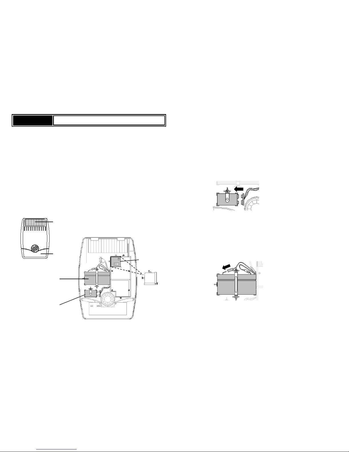
1. Open up the siren by removing the fixing screw from the bottom edge and carefully peeling off the
back cover. All electronic components are housed within the front cover.
2. Prepare the Z-wave Controller for Inclusion.
3. A 9V Alkaline b attery is supplied inside the siren to boost its initial power until the Solar Panel
charges the main battery. Locate the battery clips of this 9V battery and connect it up. The red LEDs
on the front will start to blink slowly.
4. Within 30 seconds put the Z-Wave Controller into inclusion mode.
5. The Inclusion process will be completed when the red LEDs stops blinking.
Note: If you are connecting this unit to a Z-Wave Controller that utilizes the S2 security protocol, you
may be asked by your controller to enter a 5-digit Device Specific Key (DSK) that is unique to each
unit. This can be found in one of two places:
- on the QR code label on the back of the unit
- on the insert card inside the packaging.
6. Next connect the main rechargeable battery to the charging leads. Connect the Red lead to the Red
(+ve) terminal and the Black lead to the Black (-ve) terminals.
7. The siren is now ready however do not refit the back cover just yet.
If Auto Inclusion fails, refer to the Troubleshooting section regarding Manual Inclusion
FRONT VIEW
INSIDE VIEW OF SIREN MAIN BODY
(BACK COVER REMOVED)
Solar Panel
Strobe
light &
red LED
6V 1.2Ahr
rechargeable
battery
9V initial power
up battery
Control Box –
hidden under
water proof cover
(below)
Control
box
cover
Page 2
Mounting the Outdoor Solar Siren
Choosing a location
The Siren should be mounted:
- as high as possible in a prominent position so that it can be easily seen and heard.
- on a flat surface so that the rear tamper switch is not easily activated. Ensure also that the
tamper switch does not fall into the recess between brick courses as this could prevent the switch
from closing and give a permanent tamper signal.
- ideally on a south facing wall to receive optimum amount of sunlight, but an east or west facing
wall will also suffice. Avoid mounting on a north facing wall, and avoid shadows cast by
neighboring walls, trees, and roof overhangs.
- at least 1 meter away from any external or internal metalwork which can affect its radio
transmission.
Installation
To install the siren on the wall, first affix its back cover on the wall and then followed by mounting its main
body onto the back cover.
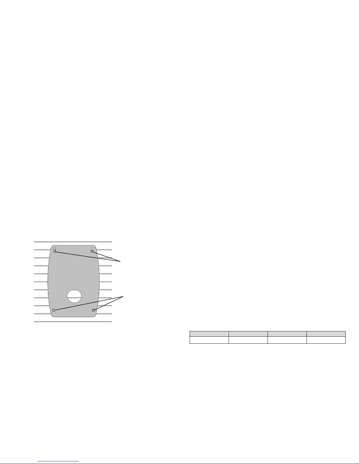
1. Remove the back cover again. Using the back cover itself as a template, position the back cover
on the wall and mark the positions of four mounting holes.
2. Drill four 6mm holes and insert the wall plugs.
3. Fit two 30mm fixing screws in the top holes leaving approximately 10mm of the screw protruding.
4. Place the top keyhole slots of the back cover over the screw heads. Adjust the back cover position
and adjust the screws until they form a neat fit with minimal movement.
5. Secure the back cover in position using the two 25mm fixing screws at the bottom.
6. Before mounting the main body, ensure the waterproof cover of the Control box has been secured
back if it was removed earlier.
7. To mount the main body, hinge the front cover tabs over the top edge of the back cover and
carefully push the base of the siren cover into place. Secure the main body in place by refitting
the fixing screw in the bottom edge of the cover. Do not over tighten the screw as this could
damage the thread.
IMPORTANT: Ensure that the rear tamper switch is closed when the main body is fitted (i.e.
listen for the switch to click). If the switch does not close, this will prevent the Siren from
operating correctly. If necessary, remove the main body again and adjust the screw on the back
cover tamper plunger to ensure the switch closes when the siren is secured in position.
Note: removing the main unit from its back plate will cause the Tamper alarm to sound. Quickly
disarm the alarm panel if this happens.
8. Upon completion of mounting the main body on the wall, the Strobe LED will flash about 3
seconds as an indication of normal operation.
Operation
1. Alarm Activation:
When an alarm is activated, the siren will activate its siren and strobe light f or 3 minutes (default
setting).
2. Alarm Length Setting:
When the siren receives an alarm signal, it will activate si ren and strobe light according to the
alarm length set by the Z-Wave controller (default is 3 minutes).
3. Ta mper Protection:
The siren is protected by a tamper switch which is compressed against the mounting surface when
mounted. Whenever the siren is removed from mounted location, or its cover opened, the tamper
switch will be activated and the siren will send a tamper open signal to remind the user of the
condition and activate an alarm immediately.
4. Siren On/Siren Off:
The siren can be closed or opened by the Z-wave controller.
Maintenance
Low Battery: Under low battery condition, the Siren will remit RF signals to the Z-Wave controller to alert
the user of its low battery condition. Replace the batteries as soon as possible.
If continue to be left unattended, the Siren will proceed to shut down but not before it transmit a last
message to the controller.
Programming
Z-Wave Group
The siren supports 1 Association Group:
Group 1: Association with 1 Controller node.
Group 1 command:
When the unit is powered up or the tamper is triggered, the unit will send a Notification Report to the
node of Group 1.
Upon siren status being changed, the unit will send Switch Binary Report to the node of Group 1.
When the battery level of the unit drops to an unacceptable level, the unit will emit Battery report to
the nodes of Group 1.
When performing Factory Reset the unit will send Device Reset Locally Notifi cation to the node of
Group1.
Z-Wave Plus Info
Role Type Node Type Installer Icon User Icon
Slave Sleeping
Listening
Z-Wave Plus node Siren Device Type Siren Device Type
Fit two 30mm fixing screws in
the top holes leaving
approximately 10mm of the
screw protruding
Secure back cover using
two 25mm fixing screws at
the bottom
Back
Cover
Page 3
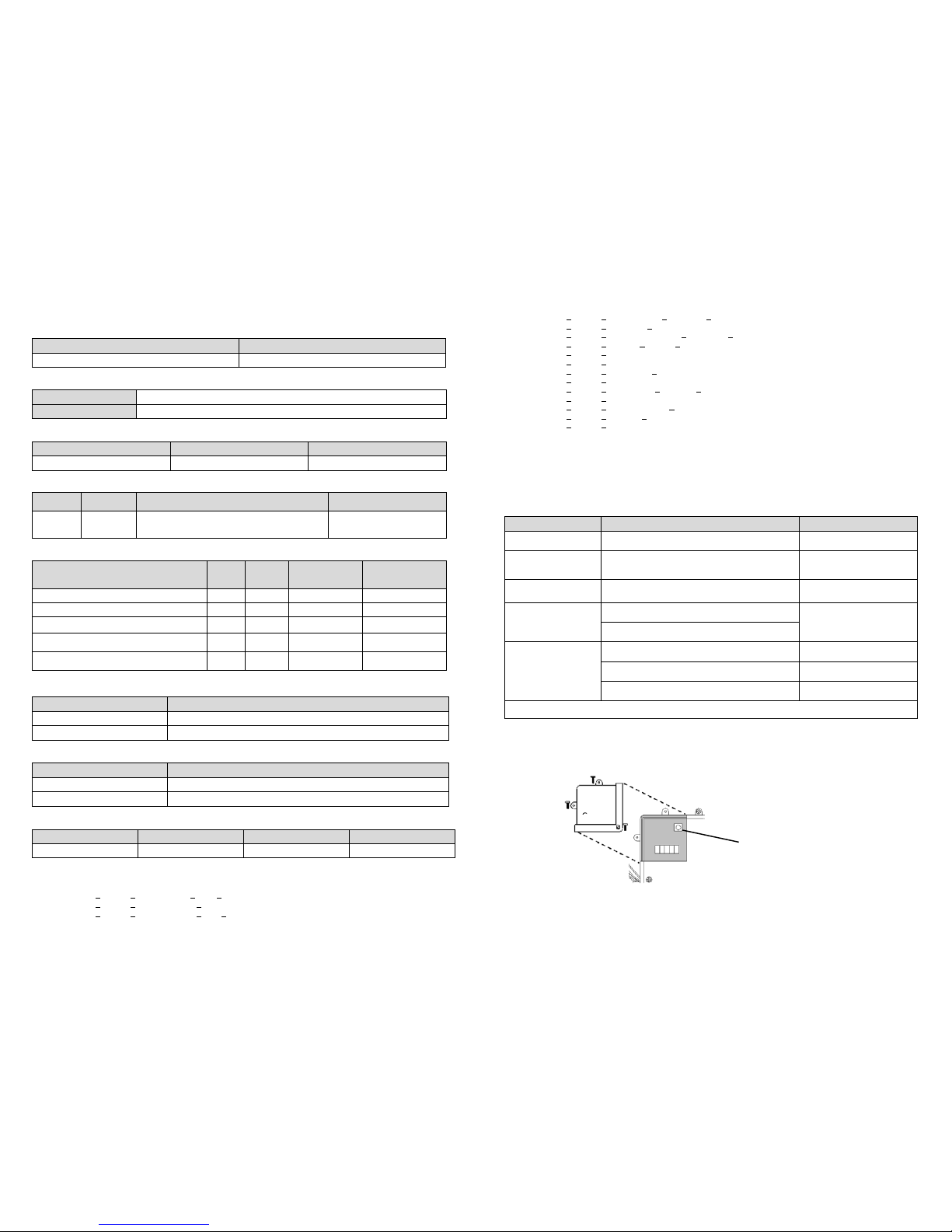
Association Command Class
Group Max Node
1 1
Version
Protocol Library 3 (Slave_Enhance_232_Library)
Protocol Version 4.3D ( 6.71.01)
Manufacturer
Manufacturer ID Product Type Product ID
0x0060 0x000C 0x0002
AGI (Association Group Information) Table
Group Profile Command Class & Command (List) N bytes Group Name(UTF-8)
1 General
Battery Report,
Device Reset Locally Notification,
Notification Report
Lifeline
Notification
Event Type Event
Event
Parameters
Length
Event Parameters
The power is applied for the first time 0x08 0x01
Shutdown occur (voltage below 5.5V) 0x09 0x07
Shutdown clear (voltage over 5.95V) 0x09 0x00 0x01 0x07
Tamper switch is p ressed more than 3
seconds
0x07 0x00 0x01 0x03
Tamper switch is pressed more than 3
seconds and released
0x07 0x03
Battery
Battery Report (value) Description
20~100 Battery Level %
0xFF Low Battery
Switch Binary
Report/Control (value) Description
0x00 Siren Off
0xFF Siren On
Configuration: Siren alarm period
Parameter Number Size Range Default
1 2 10~600 180 seconds
Command Classes
The module supports Command Classes including…
COMMAND_CLASS_ZWAVEPLUS_INFO_V2
COMMAND_CLASS_ASSOCIATION_V2*
COMMAND_CLASS_ASSOCIATION_GRP_INFO*
COMMAND_CLASS_TRANSPORT_SERVICE_V2
COMMAND_CLASS_VERSION_V2*
COMMAND_CLASS_MANUFACTURER_SPECIFIC_V2*
COMMAND_CLASS_DEVICE_RESET_LOCALLY*
COMMAND_CLASS_POWERLEVEL*
COMMAND_CLASS_SECURITY
COMMAND_CLASS_SECURITY_2
COMMAND_CLASS_SUPERVISION*
COMMAND_CLASS_FIRMWARE_UPDATE_MD_V2*
COMMAND_CLASS_BATTERY *
COMMAND_CLASS_NOTIFICATION_V4*
COMMAND_CLASS_SWITCH_BINARY*
COMMAND_CLASS_CONFIGURATION*
*Items marked an asterisk are secure command classes.
Troubleshooting
The table below lists the several steps involved when adding or removing the detector from the Z-Wave
network.
Action/Status Description LED indication
No node ID
The Z-Wave Controller does not allocate a
node ID to the unit.
2-second on, 2-second off
For 2 minutes
Auto Inclusion
The power is applied for the first time and no
node ID has been stored in the module, or after
executing reset.
Manual Inclusion Refer to the Manual Inclusion section below.
Exclusion
1. Put the Z-Wave Controller into exclusion
mode.
2. Press t he tamper switch 3 times within 1.5
seconds to put the unit into exclusion mode.
Factory Reset
(This procedure
should only be used
when the controller is
inoperable.)
1. Press the tamper switch 3 times within 1.5
seconds to put the unit into exclusion mode.
2. Within 1 second of step 1, press the tamper
switch again and hold for 5 seconds.
3. Node ID is excluded. The device reverts to
factory default state.
2-second on, 2-second off
For 2 minutes
Failed or successful results in including/excluding the ID can be viewed on the Z-Wave Controller.
Manual Inclusion
1. Locate the Control Box area and remove its waterproof cover by unscrewing it. Identify the Link
button inside.
Control
Box
Link Button
Page 4
2. With the 9V battery still connected, press the Link button 3 times within 1.5 seconds to put the unit
into inclusion mode.
3. Within 30 seconds put the Z-Wave Controller into inclusion mode.
4. The Inclusion process will be completed when the front red LEDs stops blinking.
Note: If you are connecting this unit to a Z-wave Controller that utilizes the S2 security protocol, you may
be asked to enter a 5 digit Device Specific Key (DSK) that is unique to each unit by your controller.
This can be found in one of two places:
- on the QR code label on the back of the unit
- on the insert card inside the packaging
Table below lists typical problems encountered:
Symptom
Possible Cause
Recommendation
LED not illuminating and not
working
Batteries not fitted properly or
run out of battery power.
Check if batteries are fitted or
replace a new battery.
Cannot carry out inclusion and
association
Does not fit batteries or run out
of battery power.
Check if batteries are fitted or
replace with new batteries.
Device has been paired to
other Z-Wave controller.
1. Perform Exclusion from
other controller first then carry
out inclusion with new
controller.
2. Perform Factory Reset on
device and then carry out
Inclusion with new controller.
Specifications
Battery
6V 1.2Ah Lead acid battery x 1, 9V PP3 alkaline
Range
Up to 100 meters line of sight
Alarm Sound
Min 105dBA@1m
Operating Temperature
-10°C to 40°C
Frequency Range
EU: 868.42HMz
US: 908.42 MHz
Specifications are subject to change without notice
Federal Communication Commission Interference Statement
This device complies with Part 15 of the FCC Rules. Operation is subject to the following two conditions:
(1) This device may not cause harmful interference, and (2) this device must accept any interference
received, including interference that may cause undesired operation.
This equipment has been tested and found to comply with the limits for a Class B digital device, pursuant
to Part 15 of the FCC Rules. These limits are designed to provide reasonable protection against
harmful interference in a residential installation. This equipment generates, uses and can radiate radio
frequency energy and, if not installed and used in accordance with the instructions, may cause harmful
interference to radio communications. However, there is no guarantee that interference will not occur in
a particular installation. If this equipment does cause harmful interference to radio or television
reception, which can be determined by turning the equipment off and on, the user is encouraged to try to
correct the interference by one of the following measures:
- Reorient or relocate the receiving antenna.
- Increase the separation between the equipment and receiver.
- Connect the equipment into an outlet on a circuit different from that
to which the receiver is connected.
- Consult the dealer or an experienced radio/TV technician for help.
FCC Caution: Any changes or modifications not expressly approved by the party responsible for
compliance could void the user's authority to operate this equipment.
This transmitter must not be co-located or operating in conjunction with any other antenna or transmitter.
Radiation Exposure Statement:
This equipment complies with FCC radiation exposure limits set forth for an uncontrolled environment.
This equipment should be installed and operated with minimum distance 20cm between the radiator &
your body.
Industry Canada statement:
This device complies with ISED’s licence-exempt RSSs. Operation is subject to the following two
conditions: (1) This device may not cause harmful interference, and (2) this device must accept any
interference received, including interference that may cause undesired operation.
Le présent appareil est conforme aux CNR d’ ISED applicables aux appareils radio exempts de licence.
L’exploitation est autorisée aux deux conditions suivantes : (1) le dispositif ne doit pas produire de
brouillage préjudiciable, et (2) ce dispositif doit accepter tout brouillage reçu, y compris un brouillage
susceptible de provoquer un fonctionnement indésirable.
Radiation Exposure Statement:
This equipment complies with ISED radiation exposure limits set forth for an uncontrolled environment.
This equipment should be installed and operated with minimum distance 20cm between the radiator &
your body.
Déclaration d'exposition aux radiations:
Cet équipement est conforme aux limites d'exposition aux rayonnements ISED établies pour un
environnement non contrôlé. Cet équipement doit être installé et utilisé avec un minimum de 20 cm de
distance entre la source de rayonnement et votre corps.
WARNING:
Do not dispose of electrical appliances as unsorted municipal waste, use separate collection facilities.
Contact your local government for information regarding the collection systems available.
If electrical appliances are disposed of in landfills or dumps, hazardous s ubstances can leak into the
groundwater and get into the food chain, damaging your health and well-being.
When replacing old appliances with new ones, the retailer is legally obligated to take back your old
appliance for disposal at least for free of charge.
www.everspring.com
50 Sect. 1 Zhonghua Rd Tucheng
NewTaipeiCity 236 Taiwan..
A501112750R
 Loading...