

Page 1
1
HAC01 IN-WALL REMOTE MODULE
This in-wall remote module is a transceiver which is a Z-WaveTM enabled device and
is fully compatible with any Z-WaveTM enabled network. Mini size design let the
module can easily put into the wall box and still have enough space to install the
traditional wall switch. There are many application for the module , one application is
connect the 2 wire of manual switch input to most of the wall switch sell in the
market , while the connected wall switch been switched ON or OFF , the module will
send the correspond signal to the associated devices like Z-Wave switch module
HAN01 or any Z-Wave ON/OFF or dimmer module
Another application is connect
this module to any traditional wire sensor which has NC/NO manual switch input
output, and this will easily convert those wire sensors into wireless Z-wave sensors.
With the external antenna let this module have excellent communicate RF range,
and this will let the module not only send signal to the associated device by itself
easily but also act as a good routing node in the z-wave mesh network.
Adding to Z-WaveTM Network
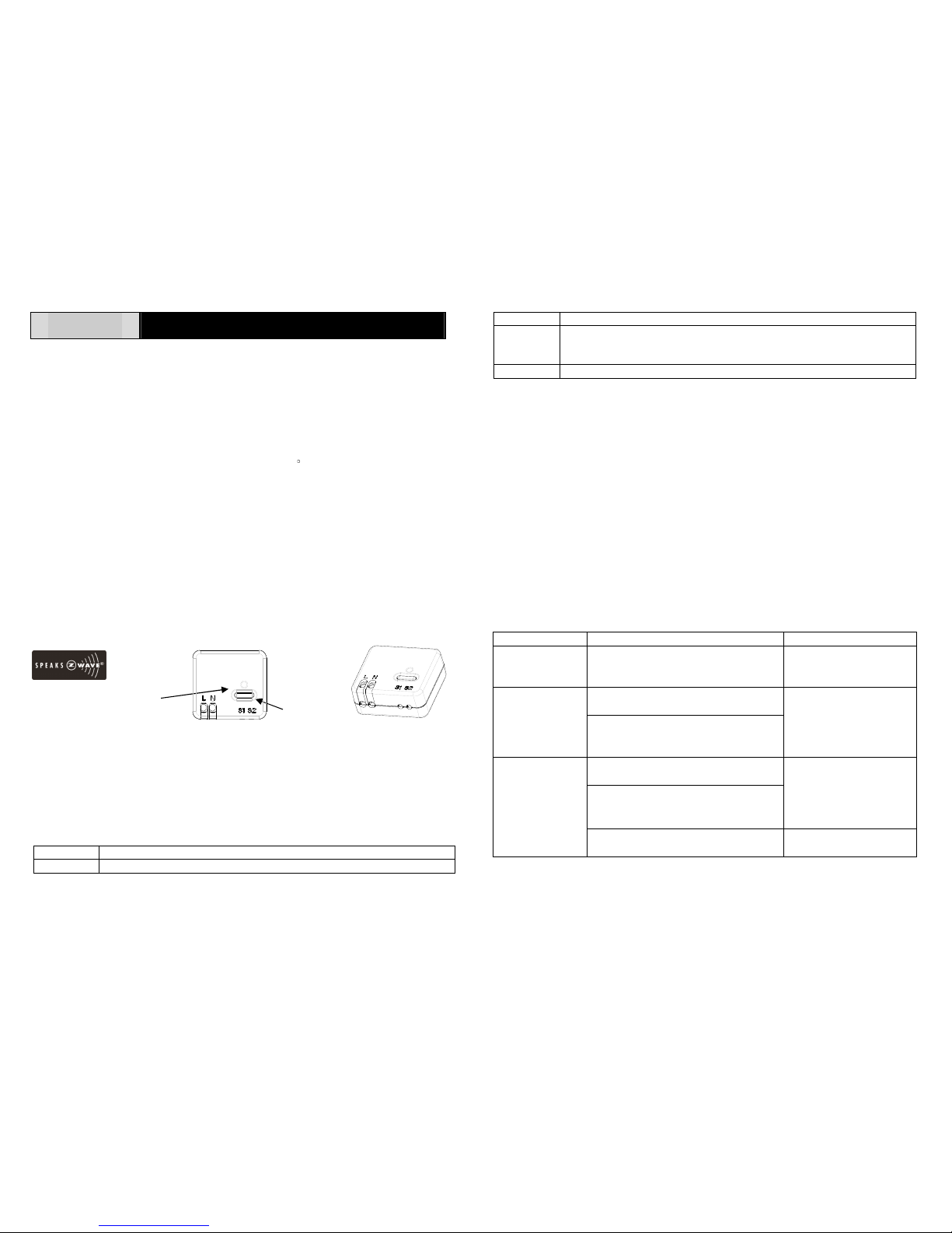
In the front casing, there is a link button with LED indicator which is used to carry out
inclusion, exclusion, reset or association.
Front View Side View
When first power is applied, the LED flashes on and off alternately and repeatedly at
2-second intervals. It implies that it has not been assigned a node ID and cannot
work with Z-Wave enabled devices. Please get familiar with the terms below before
starting the operations.
Function Description
Inclusion Add a Z-Wave enabled device to the existed Z-Wave network.
Exclusion Delete a Z-Wave enabled device from the connected network.
Association After inclusion, you have to define the relationship between devices.
Through association, device can be assigned as master or slave, and
specify which slave is going to be controlled by which master.
Reset Restore the device to factory default.
Auto Inclusion
The function of auto inclusion will be executed as long as the Module does not have
node ID when the first power is applied.
After node ID has been linked, auto inclusion will run automatically after the
execution of exclusion/reset is successful.
Note: Auto inclusion lasts for 4 minute or until the execution of inclusion is completed
during which the node information of explorer frame will be emitted once every 5
seconds. Unlike “inclusion” function as shown in the table below, the execution of
auto inclusion is free from pressing the link button on the Module.
The table below lists an operation summary of basic Z-Wave functions. Please refer
to the instructions for your Z-WaveTM Certificated Primary Controller to access the
setup function, and to include/exclude/associate devices.
Function Description LED Indication
No node ID After power is applied, if the module
does not record a node ID provided by
controller.
2-second on, 2-second off
1. Have Z-Wave remote module
entered inclusion mode.
Inclusion
2. Pressing link button three times
within 1.5 seconds will enter
inclusion mode.
When press on the link
button one time, LED
blinks for 0.5 sec. and
then off
1. Have Z-Wave remote module
entered exclusion mode.
2. Pressing link button three times
within 1.5 seconds will enter
exclusion mode.
When press on the link
button one time, LED
blinks for 0.5 sec. and
then off
Exclusion
Node ID has been excluded
successfully.
2-second on, 2-second off
Link button LED indicator
Page 2
2
1. Pressing link button three times
within 1.5 seconds .
2. Within 1 second, press link button
and hold on until LED is off.
When press on the link
button one time, LED
blinks for 0.5 sec. and
then off
Reset
3. Home ID and node ID will be
cleared and reset to factory default.
2-second on, 2-second off
Have Z-Wave remote module entered
association mode first.
Association
Pressing link button three times
within 1.5 seconds will enter association
mode
When press on the link
button one time, LED
blinks for 0.5 sec. and
then off
LED Indication
To di st in gu is h w ha t mo de t he M od ul e is i n, v ie w f rom the LED for identification.
State Type LED Indication
Normal Under normal operation with node ID, when manual switch input
from open (NO) to short(NC) or from short(NC) to open(NO), the
LED would blink for 0.5 second and then go off.
No node ID Under normal operation but without allocated node ID, the LED
flashes on and off alternately at 2-second intervals.
Programming
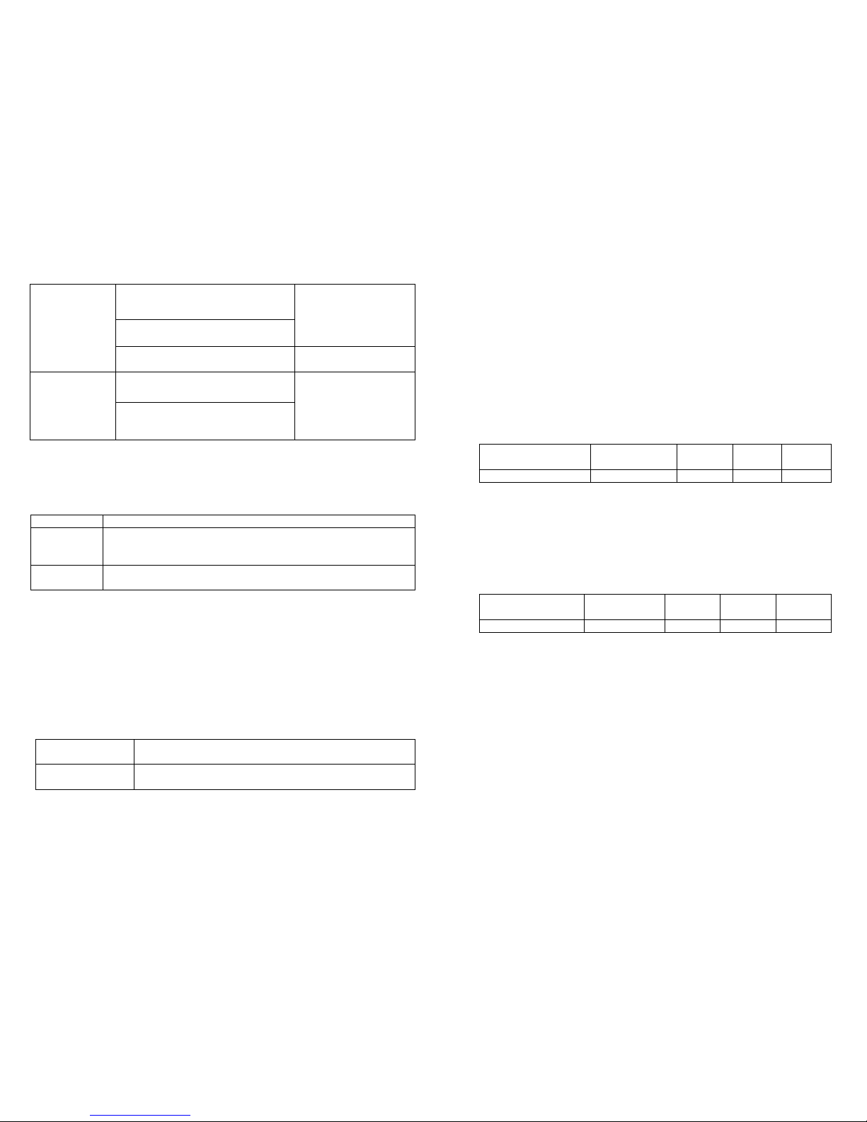
1. Z-Wave’s Grouping Feature (Association Command Class Ver 1)
The remote module supports association with maximum 5 node for Grouping 1.
Grouping 1 supports BASIC_SET
When the manual switch input is from NC to NO or from NO to NC, HAC01 would
send Basic Set Command to the nodes in Grouping 1 to On or Off the controlled
device.
Basic Set Command :
Manual switch
input at NC
Command Class Basic, Basic Set, Value = 0xFF(255)
Manual switch
input at NO
Command Class Basic, Basic Set, Value = 0x00(0)
2. Z-Wave’s Configuration
2-1. Basic Set Level
The Basic Set Command is sent with value to have the receiving device
recognize the value for controlled level, for example, if the Basic Set
Command sent to dimmer with value, the dimmer would activate the
luminance according to the value,
0 : Off
1 – 99 : On (Binary Switch Device)
Dim Level (Multilevel Switch Device)
Configuration Command
Function Parameter
Number
Size Range Default
Basic Set Level 1 1 0 ~ 99 99
2-2. Amount Of Delay (seconds)
This is applied to determine the delay time setting to send the Basic Set Off
command when the manual switch input at NO (open).
Example :
0 : immediately Off
1 – 127 : delay 1 ~ 127 second to Off
Configuration command
Function Parameter
Number
Size Range Default
Amount of delay 2 1 0 ~ 127 1
3. Supported Command Classes In Brief :
COMMAND_CLASS_SWITCH_BINARY
COMMAND_CLASS_BASIC
COMMAND_CLASS_CONFIGURATION
COMMAND_CLASS_MANUFACTURER_SPECIFIC
COMMAND_CLASS_VERSION
COMMAND_CLASS_ASSOCIATION_V1
Choosing a Suitable Location
1. Do not locate the Module facing direct sunlight, humid or dusty place.
Page 3
3
2. AC input :
AC220~240V/50Hz Europe Australia AC100~120V/60Hz US
3. The suitable ambient temperature for the Module is 0 C~40 C.
4. Do not locate the Module where exists combustible substances or any source of
heat, e.g. fires, radiators, boiler etc.
5. After putting it into use, the body of Module will become a little bit hot of which
phenomenon is normal.
Installation
Note: Please note that it is a must to call for a licensed electrician for installation.
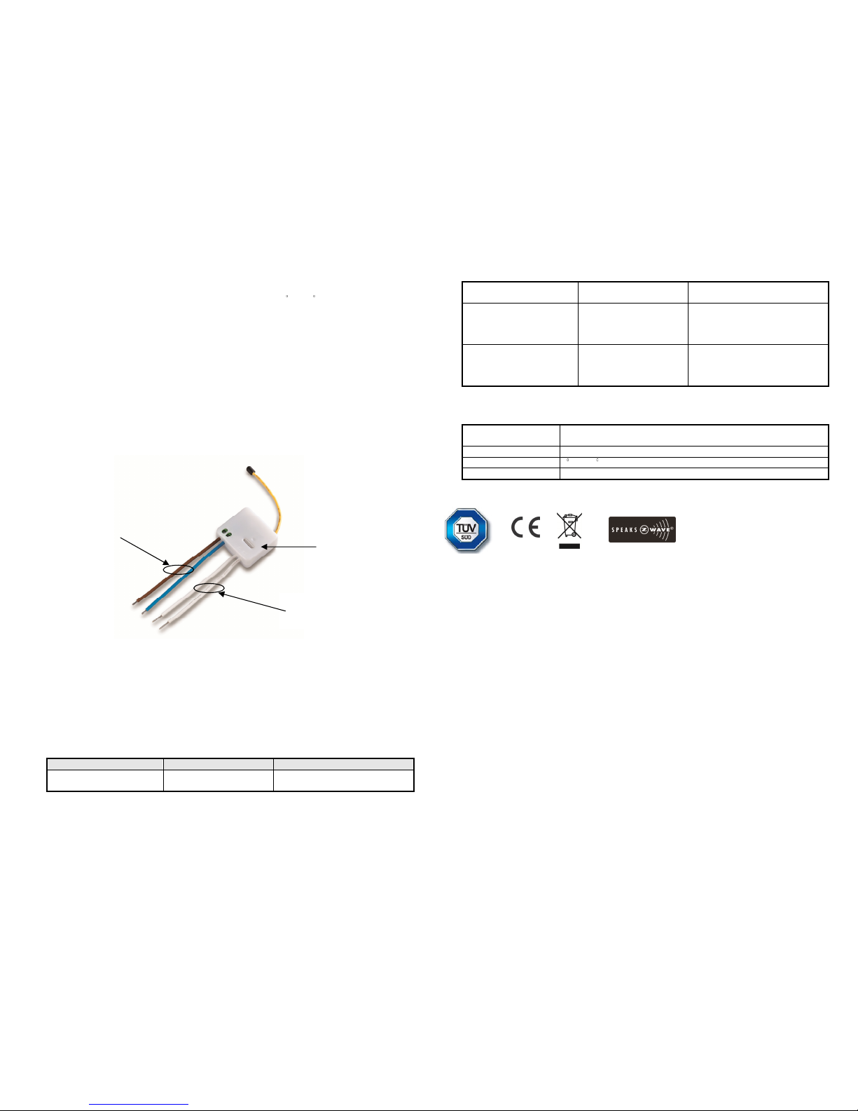
Install this Module into a wall box of which wiring connection is shown hereunder:
HAC01 can be installed into the in-wall power box, the power cord have to be
connected to the main AC power, the manual switch input cable is wired to normal
NO (open) / NC (close) button or switch. When the wiring connection is completed,
please follow the previous instruction to operate the Inclusion and Association
process to finish HAC01’s connection and network setting with controlled device (ex.
HAN01).
Tro ubles hooting
Symptom Cause of Failure Recommendation
The Module not working
and LED off
1. Improper wiring
connection
1. Check power connections
2. Don’t open up the Module and
2. The Module break
down
send it for repair.
The Module LED
illuminating, but cannot
control the ON/OFF
Switch of the load attached
Check if the load
connected to the Module
has its own ON/OFF
switch
Set the ON/OFF switch of the
load connected to ON
The Module LED
illuminating, but the
Detector cannot control
the Module
1. Not carry out
association
2. Same frequency
interference
1. Carry out association
2. Wait for a while to re-try
Specification
Power Input AC 100~240 V/50~60Hz
AC220~240V/50Hz Europe Australia AC100~120V/60Hz US
RF Operation Range Minimum 30 m indoor line of sight
Operating Temperature 0 C ~ 40 C
Frequency Range 868.42 MHz Europe 908.42MHz US 921.42MHz Australia
** Specifications are subject to change and improvement without notice.
Model number information
HAC01-0 US 908.42MHz
HAC01-1 Europe 868.42MHz
HAC01-2 Australia 921.42MHz
Warning:
Do not dispose of electrical appliances as unsorted municipal waste, use separate
collection facilities.
Link button
AC power
input
Manual switch input
Page 4

4
Contact your local government for information regarding the collection systems
available.
If electrical appliances are disposed of in landfills or dumps, hazardous substances
can leak into the groundwater and get into the food chain, damaging your health and
well-being.
When replacing old appliances with new once, the retailer is legally obligated to take
back your old appliance for disposal at least for free of charge.
 Loading...