

Page 1
ES34T
SECURITY MOTION SENSOR
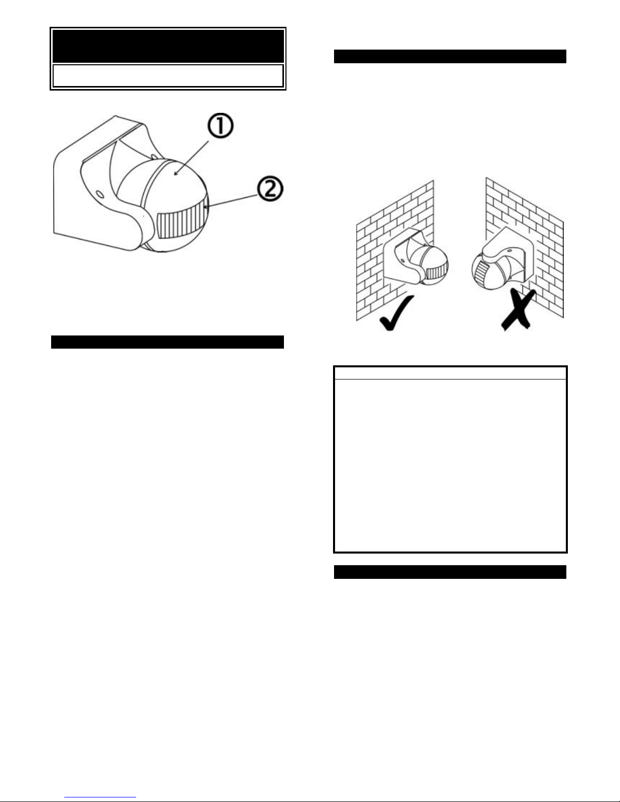
• PIR (Motion Sensor )
‚ PIR Lens
INTRODUCTION
Your EVERSPRING SECURITY MOTION SENSOR is a
fully automatic outdoor security/courtesy light controller
capable of controlling up to 1000W of lighting. At night,
the built-in passive infrared (PIR) motion sensor turns on
the connected lighting system when it detects motion in
its coverage area. During the day, the built-in photocell
saves electricity by deactivating the lights. An adjustable
timer lets you select how long the light stays on after
activation.
Two operation options - let you choose automatic
operation or manual override based on the ambient light
level.
Note : Read this entire manual before you start to
install the system.
SAFETY PRECAUTIONS
l Do not install when it is raining.
l Be sure to switch off power source before installing.
l Make sure that the power wiring comes from circuit
with an external 16A miniature circuit breaker for the
short circuit protection or a suitable fuse.
l The unit can be installed only horizontally (see the
FIGURE 1a), not vertically (see the FIGURE 1b) as
shown in the below drawing.
HORIZONTAL VERTICAL
FIGURE 1a & 1b
IMPORTANT
Some local building codes may require installation of
this product by a qualified electrician.
Check your local codes as they apply to your situation.
If the house wiring is of aluminum,
consult with an electrician about proper wiring
methods.
Before proceeding with the installation, TURN OFF
THE POWER TO THE LIGHTING CIRCUIT AT
THE CIRCUIT BREAKER OR FUSE BOX TO
AVOID ELECTRICAL SHOCK.
CHOOSING A MOUNTING LOCATION
l For the best results, fix your sensors on a solid
surface. For wall mounting, 1.8~2M above the
ground is needed. For ceiling mounting, 2.5~4M
above the ground is required.
l For outdoor installation, a location under eaves is
preferable.
l Avoid aiming the motion sensor at pools, heating
vents, air conditioners or objects which may change
temperature rapidly.
l Do not allow sunlight to fall directly on the front of
unit.
l Try to avoid pointing the unit at trees or shrubs or
where the motion of pets may be detected.
1
Page 2

l Prior to mounting, keep in mind that the motion
sensor is most sensitive to the motion, which is
across the detection field and less sensitive to the
motion, which moves directly towards the
detector.
(FIGURE 2)
SENSOR SENSOR
LESS SENSITIVE MORE SENSITIVE
SENSITIVITY TO MOTION
FIGURE 2
INSTALLATION
To facilitate installation, it is essential to get a drill and
a screwdriver ready. Select a location for the unit based
on the coverage angles shown in FIGURE 3.
FIGURE 3
Install a wall switch adjacent to the power source.
(FIGURE 4 & 5) This helps you operate AUTO and
MANUAL OVERRIDE with ease. See page 4 for
further information.
Type I:
FIGURE 4
Type II:
FIGURE 5
2
Note : The detection angle of ES34T can come up to180°.
However to reduce or localize its detection coverage, use
the small plastic slip(s) provided to cover up part(s) of the
LENS, thus reducing its detection angle. (FIGURE 6)
FIGURE 6
WIRING INSTRUCTION
(1) Switch off the power source or wall switch.
(2) Unscrew two front screws to detach the base cover
from the unit. (FIGURE 7)
(3) Make use of the base cover as a template to mark
the position of two screw holes on the wall. Drill
the wall and screw the base cover onto the wall
using suitable plastic wall plugs and screws
provided. (FIGURE 8).
FIGURE 8
(4) Strip approximately 6-8mm insulating part of the
wires from the power cord. Before connection,
run the wires through the rubber seal provided.
Note: The power cord must meet H05RN-F,
1.0mm² requirement.
3
Page 3

For power wire connection,
Type I :
Connect the BROWN wire (Live wire) to the terminal
block “L” mark.
Connect the BLUE wire (Neutral wire) to the terminal
block “N” mark. (FIGURE 9)
FIGURE 9
Type II:
Connect the YELLOW/GREEN (Ground wire) to the
terminal block . (FIGURE 10)
Connect the BROWN wire (Live wire) to the terminal
block “L” mark.
Connect the BLUE wire (Neutral wire) to the terminal
block “N” mark.
FIGURE 10
(5) For lamp wire connection,
Connect the 'BLUE' wire to the terminal block 'N'
mark.
Connect the 'BROWN' wire to the terminal block 'LS'
mark.
Note: For the ES34T, besides the above mentioned
two points, you have to connect the
‘YELLOW/GREEN’ wire to the terminal block.
(7) Fix the pre-wired terminal block to the boss of base
cover tightly. Place and fix the rubber seal to the wire
outlet.
4
(8) Refit and screw the unit to the base cover.
SETTING THE LIGHTING SYSTEM
(1) TEST MODE
l Turn the Lite control and the Time control anti-
clockwise to the edge – the TEST position (FIGURE
11)
FIGURE 11
l Turn on the wall switch. The light will turn on for
about 1 minute to warm up. Then it turns off.
l Walk through the detection area. The light turns on
when you move and turns off when you stop. Wait
for the light to turn off before moving again to test the
sensor.
l Adjust the motion sensor to cover the desired
detection area. For a smaller coverage area, point
the sensor down; for a larger coverage area, point
the sensor up.
(2) TIME ADJUSTMENT
The TIME adjustment controls how long the light will stay
on after the motion has been detected.
Turn the TIME control knob clockwise to increase (up to
about 12 minutes) how long the lights stay on or anticlockwise to decrease (down to about 5 seconds) the
time delay. (FIGURE 12)
FIGURE 12
(3) LITE ADJUSTMENT
The LITE adjustment determines at what light level the
lighting system will start operating when you set the
sensor to automatic operation.
Provisionally turn the LITE control knob to the edge
clockwise at the moon (dusk) position (FIGURE 13).
In this provisional setting mode, the Motion Sensor
remains inactive during daylight. At dusk when you find it
is the LUX level desired for operation, simply set the LITE
control knob to the position which becomes active as
daylight declines.
5
Page 4

FIGURE 13
OPERATION
By using wall switch to your ES34T, you can easily
select one of two modes of operation: automatic
operation and manual override.
(1) AUTOMATIC OPERATION
Turn on the wall switch. When the sensor detects
motion, the light automatically turns on. The built-in
photocell turns the sensor off and on according to the
light level selected by the Lite adjustment.
(2) MANUAL OVERRIDE
To keep the light on regardless of the motion, you can
override the Automatic Operation. Turn the wall switch off
and on twice within 4 seconds. The interval between the
first and second operation must be within 0.5 - 2
seconds.
In Manual Override mode, the light will remain on for
around 4 ~ 6 hours despite no motion; then the light will
turn off and the motion sensor will be back to Auto
Operation mode automatically.
Users can also set the motion sensor back to Auto
Operation by turning off the wall switch for at least 10
seconds and then turn it back on.
TROUBLESHOOTING
Light does not turn on
l Confirm that you have made a correct “wiring
connection”.
l Make sure that the bulbs have not burned out.
Light remains on
l Make sure the wiring connection is correct.
l If you set the system to manual override, remember
that you must turn the wall switch off for at least 10
seconds to switch the sensor to automatic
operation and turn off the lights.
l Check if the TIME setting is correct.
6
SPECIFICATIONS
Detection Method Passive infrared
Power Requirement AC 220 - 240V/ 50Hz
Lighting Load
(Incandescent)
Max. 1, 000W
Tungsten
10* Max.40W
Fluorescent
Power Cord Requirement
H05RN-F, 1.0mm²
Sensor Power
Protection Class Class II
Waterproof IP44
Operating
Temperature -20° C to +40°C
Detection Range
Up to 12m (39.4ft) at 20° C,
2m Height
Sensor Adjustments
Detection Angle Up to 180° at 20°C, 2m Height
Swiveling Angle Vertical 220°
Warm Up Time About 1 minute
Time Adjustment From 5± 3 seconds to
12± 3 minutes
Lux Adjustment Approx 0 Lux to 1,000Lux.
Mounting Height 1.8 to 2M (5.9 to 6.6 Feet)
Wall Mount
2.5 to 4M (8.2 to13.2 Feet)
Ceiling Mount
Switch Function Off/Auto/Manual Override
INES34TEVSPEA.
7
 Loading...