

Page 1
1
ES160
Z-wave
plus
outdoor PIR motion
detector module
The ES160 is a PIR module to retrofit onto existing outdoor floodlight. It features a
PIR detector to detect motion through movement of heat sources and a lux sensor
for determining brightness of its surroundings. It is equipped with Z-wave
plus
wireless communication capability to upgrade the ordinary outdoor floodlight into a
smart home device.
When not connected to a Z-wave network, ES160 when fitted on a floodlight is
fully operational as a standalone security floodlight. During hours of darkness its
PIR detector turns on the floodlight when it detects movement in the protected
area. Its built-in timer will then turn off the floodlight after a preset time has elapsed.
During daylight hours, its lux sensor saves energy by deactivating the motion
sensor and the floodlight. The lux level and the timer can be set through knobs on
the device itself.
When added into a Z-wave network, ES160 communicates directly with other end
devices such as smart plugs, or to report directly to a Z-wave controller (usually a
gateway). It alerts the controller when motion is detected and through Z-wave
commands, the controller can remotely turn on/off the floodlight at any time and be
able to configure its lux level and timer setting.
This product supports the S2 security protocol that uses encrypted Z-Wave
plus
messages to communicate to other security-enabled Z-Wave
plus
products. A
security-enabled Z-Wave
plus
Controller must be used in order to fully utilize the
security features of this product.
ES160 can be installed on standard external outdoor lighting fixture without a
motion sensor, or to replace existing motion sensor on security floodlights.
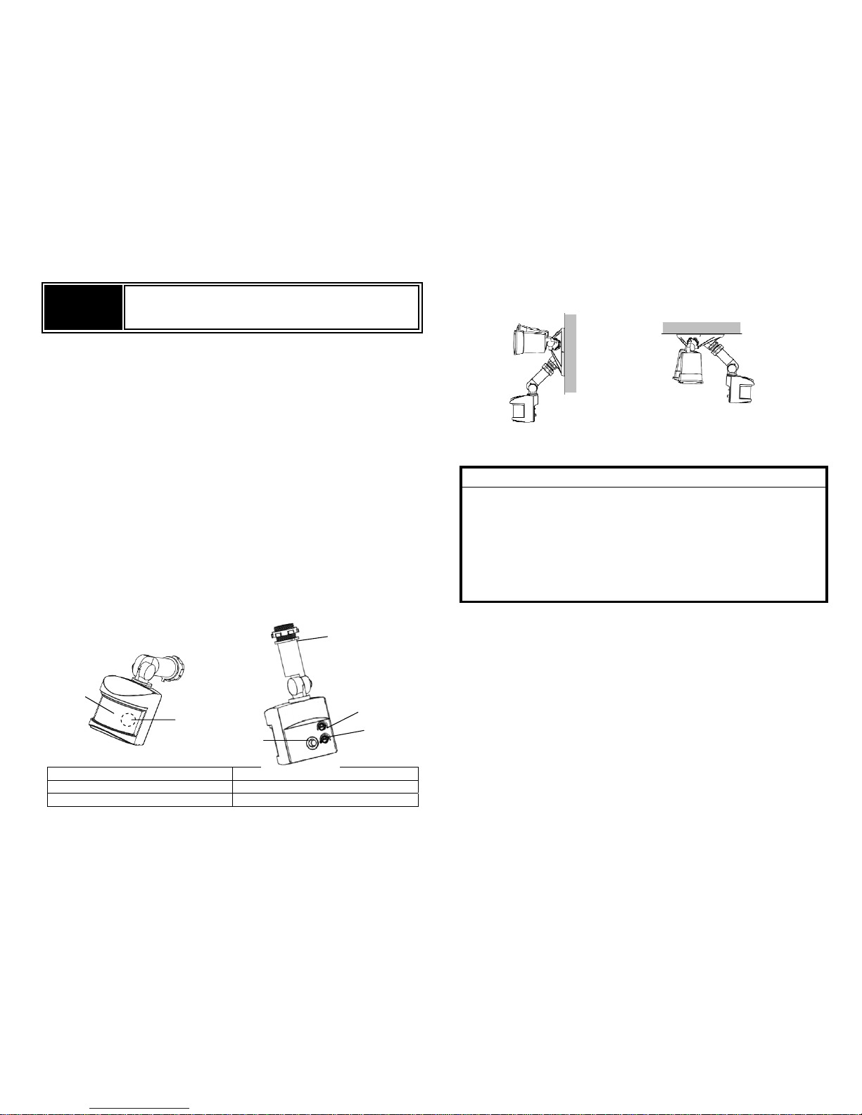
Product Overview
PIR Lens Lux knob
LED indicator (hidden behind lens) Timer Knob
Link button Threaded arm
Below diagram show a typical assembly of ES160 onto a floodlight fixture (fixture
is not included).
(Wall mount) (Under Eave mounting)
Note: Please read this entire instruction manual before you start the installation.
IMPORTANT
Installation must be performed by skilled technicians who are informed
about the standards and technical requirements of the appliance and its
proper installation.
Check your local codes as they apply to your situation. If the house wiring is of
aluminum, consult with an electrician about proper wiring methods.
Before proceeding with the installation, TURN OFF THE POWER TO THE
LIGHTING CIRCUIT AT THE CIRCUIT BREAKER OR FUSE BOX TO AVOID
ELECTRICAL SHOCK.
SAFETY PRECAUTION
DO NOT install when it is raining.
Isolate the power supply before installation.
Ensure that local Wiring and Building regulations are complied with.
The unit is supplied with a pre-wired supply cable this must be used and must
not be removed.
Total lighting load to ES160 not exceed:
- 300W incandescent @ AC120V
- 100W LED @ AC120V with 0.8 pF Driver
Installation & Wiring instructions
Note : As with any outdoor inst allation work it is always recommended to start
early during the day.
Page 2
2
WARNING : TURN OFF POWER BY REMOVING POWER FUSE OR TURNING
OFF CIRCUIT BREAKER BEFORE INSTALLATION.
Taking down the existing floodlight
1. With mains supply turned off, if possible remove the lamps from the bulb
holders of the existing floodlight to avoid any damage during the installation.
2. Carefully detach the floodlight from the wall by removing its mounting screws.
Keep all parts for reuse later, including any rubber rings. Take note the
direction of the rubber gasket as it needs to be reassembled later in the same
way.
3. Disconnect the mains wire from the floodlight by untwisting the wire nuts.
4. When done, place the floodlight on a table to prepare for wiring the ES160.
Removing old motion sensor
(Skip this section if the existing floodlight has no motion sensor)
5. Locate the wires coming from the old motion sensor, usually colored black,
white and red.
6. Disconnect the wires of the motion sensor by cutting it if necessary.
7. Remove the old motion sensor from the mounting base by twisting its
threaded arm counter clockwise.
Wiring up the ES160
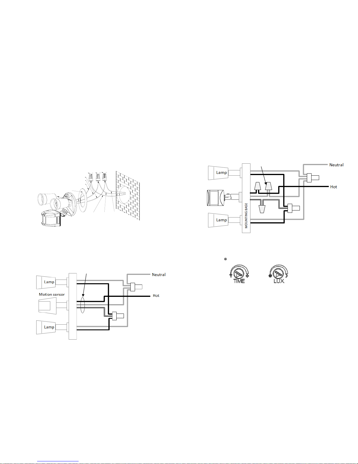
8. Screw the threaded arm of ES160 into the mounting base. For typical wall
installation, ES160 should be located at the bottom of the mounting base.
9. Connect up the wiring as in the diagram below, using wire nuts to join the
wires. If replacing an old motion sensor, simply follow the same wiri ng color as
the old motion sensor.
10. Route the power leads Hot and Neutral through the rubber gasket to get ready
for wall mount. Ensure the rubber gasket is facing the same direction as it was
before.
11. When completed, turn the Timer knob on the unit to “T” mark, and turn the Lux
knob to the “
” mark.
Assembling back the floodlight
12. Connect back the mains wire as before. Tuck the wire nuts and excess cable
neatly inside the junction box.
13. Screw the lighting floodlight back into position using its mounting screws.
Place the rubber rings back into their positions.
14. Insert the lamps removed earlier back into the bulb holders, adjust the lamp
direction if necessary .
15. Reinstate the power supply to the floodlight and switch on the wall switch, if
installed. The floodlight will turn on for around 5 seconds for warm up and
then turn off. It is now in ‘Test Mode’.
Yellow/Green
Black
White
Earth
GASKET
Live
Neutral
Cut here
BLACK
WHITE
RED
RED
WHITE
BLACK
Wire nut
ES160
Page 3
3
Walk Test
The user can perform a walk test to ensure the PIR detector’s range falls within
the desired area of coverage.
1. Walk through its PIR Detector coverage area. The floodlight turns on when
you move and turns off after approximately 5 seconds. Wait for the floodlight
to turn off before the next test.
2. When you are satisfied with the coverage area you can now set the desired
Time period and Lux level.
Time and Lux adjustment
Y ou can set desired Time period and Lux level through;
(i) the Z-Wave controller after connecting to a Z-wave network (see next section)
or,
(ii) manually adjusting the knobs on the unit if not connected to a Z-wave
network. The following section describes the steps for manual setting.
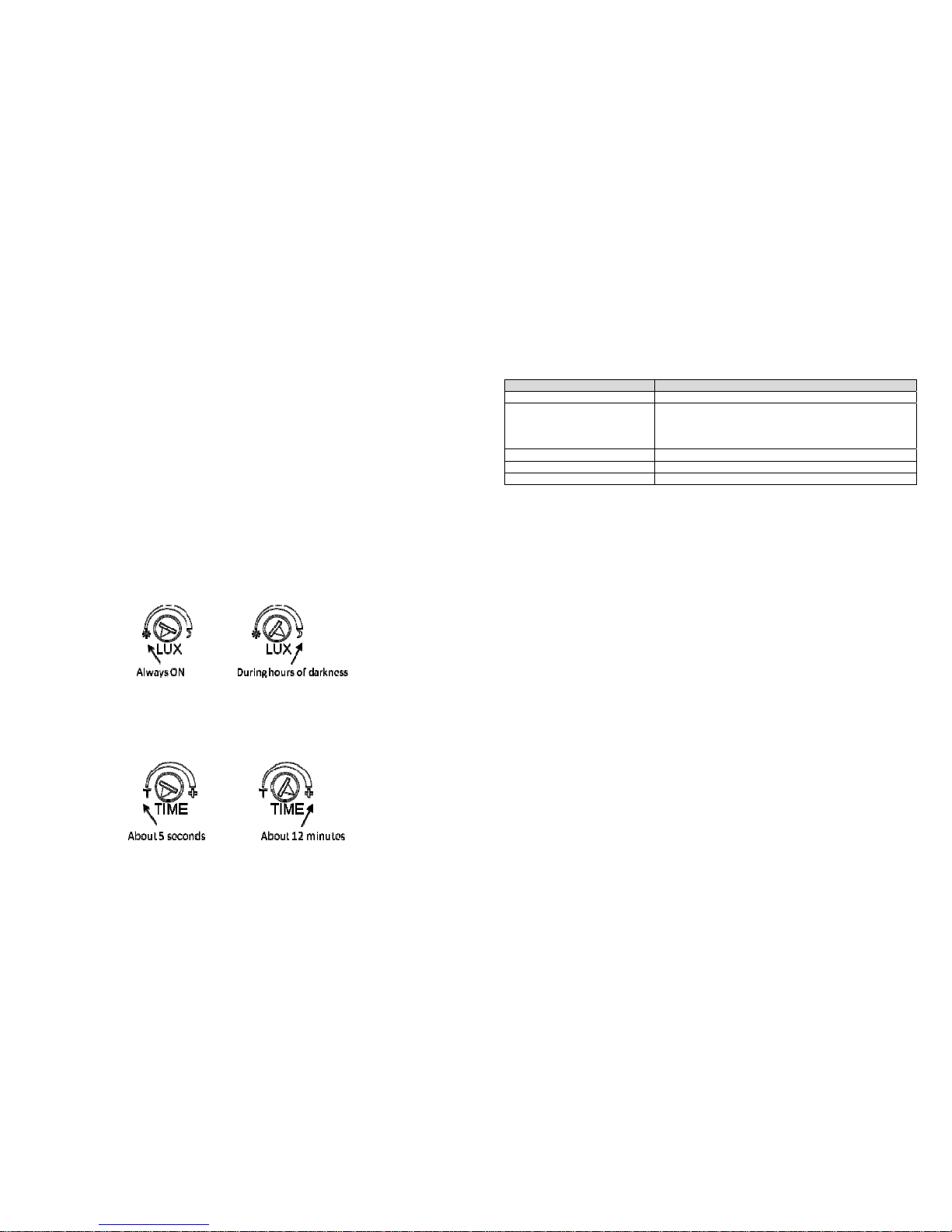
(1) Time adjustment
Time-off knob controls how long the floodlight will stay on after the motion is
detected. Turning the knob towards the + sign increases the time (up to about
12 minutes) or towards the T decreases it (down to about 8 seconds). The
recommended setting is around midpoint of the scale giving approximately 5
minutes.
(2) Lux level adjustment
The LUX knob sets the threshold of ambient brightness level that will activate
the motion sensor. The knob can be adjusted between T (always trigger
regardless of light level) and the moon symbol (trigger only when dark). The
adjustable Lux range is about 30 - 200 Lux.
1. To set the lux level, turn the Time-off knob to “T” for maximum response.
2. Turn the LUX control knob to the “moon” (dusk) position.
3. Wait until the ambient light reaches the level of darkness at which you wish
the floodlight to activate.
4. Slowly rotate the Lux knob anti-clockwise while keep creating motion during
the process until the floodlight turns on. At this positio n the light will operate at
approximately the same level of darkness each evening.
5. Set the Time-off knob back to the desired preset time.
Note: When connected to a Z-wave controller, this manual setting will be
overwritten by the settings through the Z-wave controller.
Commands from Controller Commands
Turn on Floodligh
t
Switch Binary Set On/ Basic Set On
Turn off Floodlight
Switch Binary Set Off/ Basic Set Off.
Note: The floodlight will revert back to its own self
control onl
y
after this command is sent.
Set Timer Configuration settings, Parameter 1
Set Lux level Configuration settings, Parameter 2
Read Lux level Multilevel sensor : 0x03
Z-wave Auto Inclusion
The unit supports Auto Inclusion feature where it will automatically enter Inclusion
mode when first powered up after a factory reset.
1. Turn off power to the floodlight by turning off the wall switch.
2. Try to relocate the Z-wave controller nearer to the floodlight, with at most one
wall separation between them.
3. Put the Z-Wave Controller into Inclusion mode.
4. Turn on the wall switch of the floodlight. The floodlight will then turn on for 5
seconds and the LED indicator will start to blink slowly.
5. When the LED indicator stops blinking the Inclusion process is complete.
Note: If you are connecting this unit to a Z-wave controller that utilizes the S2
security protocol, you may be asked by your controller to enter a 5-digit
Device Specific Key (DSK) that is unique to each unit. This can be found in
one of two places:
- on the QR code label on the back of the unit
- on the insert card inside the packaging.
6. Turn on the floodlight using the Z-wave controller to check if the auto inclusion
is working properly.
If Auto Inclusion fails, refer to the Troubleshooting section regarding Manual
Inclusion
Operation
Z-Wave Group
The unit supports either one of two Z-wave Association Groups:
Group 1: Association with 1 Controller node.
Group 2: Association with 4 nodes (i.e. end devices such as smart plugs and
other lighting controllers). This allows the PIR detector on the unit to transfer
commands directly to other Z-wave end devices without the participation of the
controller. This has the effect that when its dete ctor triggers, all devices associated
with unit will be operated.
Page 4
4
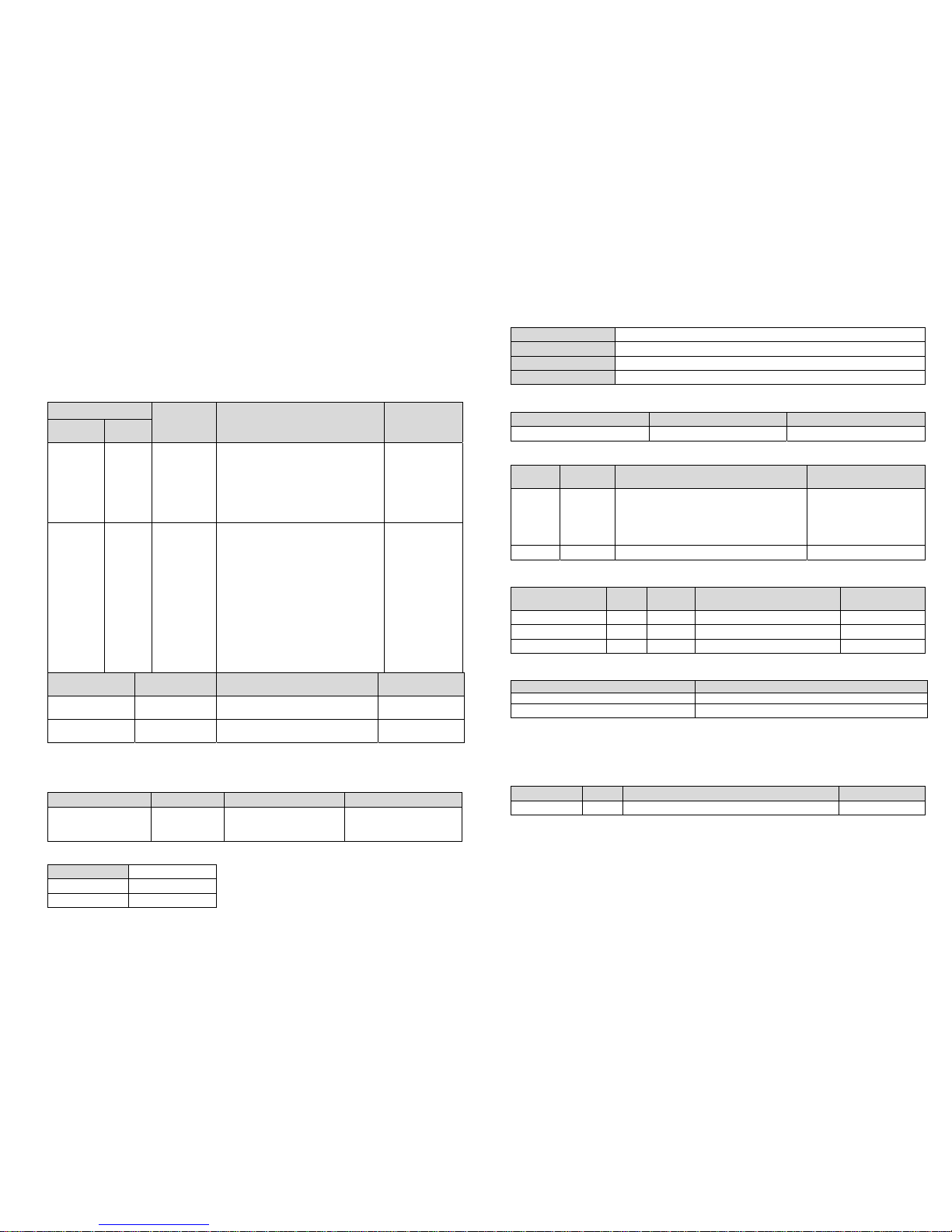
Command overview
Table below are control commands that can be sent from the controller. Refer to
Programming section for details on sending these commands.
Notification overview
Table below shows the notifications sent by the unit whenever an event occurs.
Refer to Programming section for details of these notifications.
Sensor Event
Floodlight
behavior
Z-wave commands/notification Remark
Lux
sensor
PIR
sensor
Daylight Trigger Off
When Trigger:
- Notification, PIR Trigger ON :
Group 1
When timer expire :
- Notification, PIR Trigger OFF:
Group 1
Z-wave
command is
sent even if
floodlight is
off
Night,
or
Lux
knob set
to "T"
Trigger
On, until
timer
expires
When Trigger:
- Notification, PIR Trigger ON :
Group 1
- Switch Binary Report : Group
1
- Basic Set On : Group 2
When timer expire :
- Notification, PIR Trigger OFF:
Group 1
- Switch Binary Report : Group
1
- Basic Set Off : Group 2
Other Events
Floodlight
behavior
Z-wave
commands/notification
Remark
1st power on On for 5
seconds
Notification : First Power Up :
Group 1
Device
Factory reset
N
A
Device Reset Locally
Notification : Group 1
Programming
Z-Wave Plus Info
Role Type Node Type Installer Icon User Icon
Slave Always ON Z-Wave
Plus node
Sensor Notification
Device Type (Home
Securit
y)
Sensor Notification
Device Type (Home
Securit
y)
Association Command Class
Group Max Node
1 1
2 4
Version
Protocol Library 3 (Slave_Enhance_232_Library)
Protocol Version 5.3 ( 6.71.03)
Firmware Version xVy (x=1,y=1 means 1V1)
Hardware Version 1
Manufacturer
Manufacturer ID Product Type Product ID
0x0060 (Everspring) 0x0010 0x0001
AGI (Association Group Information) Table
Group Profile
Command Class & Command (List)
N bytes
Group Name(UTF-8)
1 General
Device Reset Locally Notification
Notification Report
Binary Report
Sensor Multilevel Report
Basic Repor
t
Lifeline
2 Control Basic Set PIR Control
Notification Report
Event Type Event Event Parameters Length
Event
Parameters
First power up 0x08 0x01 0x00
PIR Trigger ON 0x07 0x08 0x00
PIR Trigger OFF 0x07 0x00 0x01 0x08
Switch Binary: LED Floodlight Status
Switch Binary Report (value) Description
0x00
Floodlight is o
ff
0xFF Floodlight is on
Z-wave Configuration settings
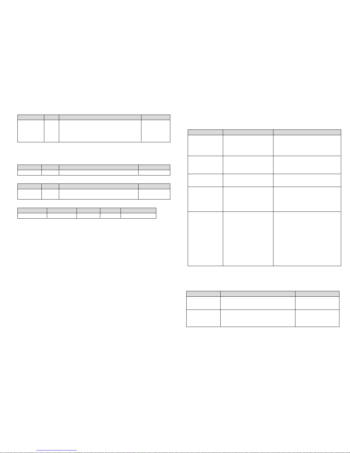
1. PIR Trigger Off period : Period to send Trigger Off command after PIR is
triggered. Before this period expires, the PIR will not be able to detect any
subsequent motion.
Parameter Size Range Default
1 2 8~720 secs 15
3. Lux sensor threshold : Ambient Lux level to turn on light. This setting
overwrites the Lux level set by the Lux knob. When the lux level falls below
this threshold and the PIR gets triggered, the floodlight will turn on.
Page 5
5
Parameter Size Range Defaul
t
2 2
When PIR triggers:
30~200 : Lux level to turn on floodlight
0 : Floodlight always off
255: Floodlight always on
50
Regardless of this setting, the PIR will always send a notification report to the
controller when triggered.
3. Auto Report luminance interval : sets the interval of periodic lux level report to
the controller.
Parameter Size Range Default
3 2 0~1440 (min.) 0 (OFF)
4. Basic Report : Enable/Disables Basic Report commands
Parameter Size Range Default
4 1
0 : Disable Basic Report
1 : Enable Basic Report
1 (Enable)
5. Multilevel Sensor : Reads back the lux level measured. (Tolerance of ±30 lux.
Level above 250 will be read back as 250)
Sensor Type Precision Scale Size Sensor Value
0x03 0 1 2 <250
Command Classes
The module supports Command Classes including…
COMMAND_CLASS_ZWAVEPLUS_INFO_V2
COMMAND_CLASS_ASSOCIATION_V2
COMMAND_CLASS_ASSOCIATION_GRP_INFO
COMMAND_CLASS_TRANSPORT_SERVICE_V2
COMMAND_CLASS_VERSION_V2
COMMAND_CLASS_MANUFACTURER_SPECIFIC_V2
COMMAND_CLASS_DEVICE_RESET_LOCALLY
COMMAND_CLASS_POWERLEVEL
COMMAND_CLASS_SECURITY_2
COMMAND_CLASS_SUPERVISION
COMMAND_CLASS_FIRMWARE_UPDATE_MD_V4
COMMAND_CLASS_NOTIFICATION_V4
COMMAND_CLASS_SWITCH_BINARY
COMMAND_CLASS_SENSOR_MULTILEVEL_V7
COMMAND_CLASS_CONFIGURATION
COMMAND_CLASS_SENSOR_BINARY
Troubleshooting
Table below lists typical problems encountered:
Symptom Possible Cause Recommendation
Floodlight does
not turn on for 5
seconds after
power is
connected.
Power is not connected
properly.
Check if wall switch is on.
Confirm wiring is correct.
Check supply breaker / fuse.
Cannot carry out
inclusion and
association
Floodlight already paired
to another Z-Wave
Controller.
Perform a factory reset.
Floodlight
flashes on and
off
The unit’s lux sensor is
being triggered off by
reflected li
ght
Change the angle and direction of
the lamps.
Z-wave
controller cannot
communicate
with the unit
Out of range. 1. Relocate the controller closer
to the unit.
2. Install a Z-wave repeater such
as smart plugs or other AC
devices that can operate as a
Re
p
eater.
Floodlight
remains on
PIR detector
triggered by
unknown heat
source.
1. Check time setting
2. Cover the PIR Detector with
black insulating tape. If after
the timer expires and the
floodlight turns off this
indicates that the PIR
Detector can see a moving
heat source e.g: radiator,
heater, boiler outlet, open
window, open exterior door or
moving branches or bushes
retaining heat from the
da
y
time period.
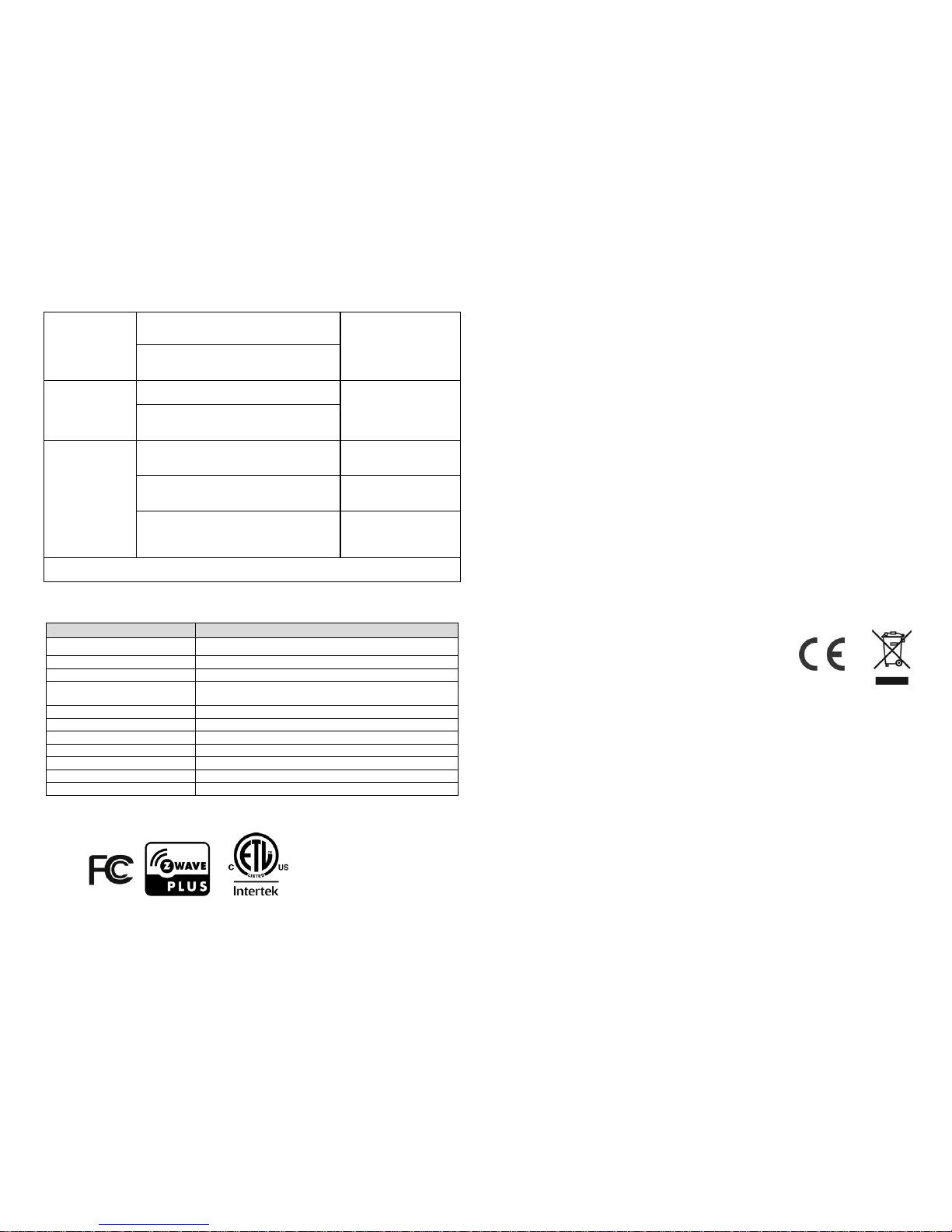
Manual Inclusion/Exclusion
The table below lists the several steps involved when adding or removing the u nit
from the Z-wave network.
A
ction/Status Description LED indication
No node ID
The Z-Wave Controller does not
allocate a node ID to the unit.
2-second on,
2-second off for 2
minutes.
Auto Inclusion
The power is applied for the first time
and no node ID has been stored in the
module, or after executing reset. This
process times out in 30 seconds.
Page 6
6
Manual
Inclusion
1. Put the Z-Wave controller into
inclusion mode.
2. Press the Link button 3 times within
1.5 seconds to put the unit into
inclusion mode.
Exclusion
1. Put the Z-Wave Controller into
exclusion mode.
2. Press the Link button 3 times within
1.5 seconds to put the unit into
exclusion mode.
Factory Reset
(This procedure
should only be
used when the
controller is
inoperable.)
1. Press the Link button 3 times within
1.5 seconds to put the unit into
exclusion mode.
2. Within 1 second of step 1, press
the Link button again and hold until
LED is off (about 5 seconds).
3. Node ID is excluded. The device
reverts to factory default state and
will be in auto-inclusion mode for 4
minutes.
Failure or success in Inclusion/Exclusion can be viewed on the Z-Wave
Controller user interface.
Specifications
Frequency Range 908.42 MHz (US) / 868.42 MHz (EU)
PIR Tilting Angle 140∘
Mounting Height Recommended 1.8 ~ 2.0m on Normal Brick Wall
PIR Detection area
Max. distance 12m, max. angle of120°
(@
1.9m height, 20°C ambient temperature
)
PIR Swivel Angle Up to 90° Leftward, Up to 90° Rightward
PIR warm-up time 5 secs maximum
Lux Adjustment
A
pproximately 30 ~ 200 Lux
Timer Adjustment
A
pproximately 8 seconds ~ 12 minutes
Working T e mperature -20°C - +40°C
Dimension (H x W x D
)
60mm x 55mm x 60mm
Protection Degree IP44 – Weather proof
Specifications are subject to change without notice
A501112772R
Federal Communication Commission Interference Statement
This equipment has been tested and found to comply with the limits for a Class B
digital device, pursuant to Part 15 of the FCC Rules. These limits are designed
to provide reasonable protection against harmful interference in a residential
installation. This equipment generates, uses and can radiate radio frequency
energy and, if not installed and used in accordance with the instructions, may
cause harmful interference to radio communications. However, there is no
guarantee that interference will not occur in a particular installation. If this
equipment does cause harmful interference to radio or television reception, which
can be determined by turning the equipment off and on, the user is encouraged to
try to correct the interference by one of the following measures:
- Reorient or relocate the receiving antenna.
- Increase the separation between the equipment and receiver.
- Connect the equipment into an outlet on a circuit different from that to which
the receiver is connected.
- Consult the dealer or an experienced radio/TV technician for help.
This device complies with Part 15 of the FCC Rules. Operation is subject to the
following two conditions: (1) This device may not cause harmful interference, and
(2) this device must accept any interference received, including interference that
may cause undesired operation.
FCC Caution: Any changes or modifications not expressly approved by the party
responsible for compliance could void the user's authority to operate this
equipment.
This transmitter must not be co-located or operating in conjunction with any other
antenna or transmitter.
WARNING:
Do not dispose of electrical appliances as unsorted municipal waste, use sepa rate
collection facilities.
Contact your local government for information regarding the collection systems
available.
If electrical appliances are disposed of in landfills or dumps, hazardous
substances can leak into the groundwater and get into the food chain, damaging
your health and well-being.
When replacing old appliances with new ones, the retailer is legally obligated to
take back your old appliance for disposal at least for free of charge.
3F., No. 50, Sec. 1 Zhonghua Rd. Tucheng Dist.,
New Taipei City 236, R.O.C..
 Loading...