

Page 1
AC136
Panic Button
The AC136 Panic Button is a Z-Wave PlusTM enabled device and is fully compatible with any Z-WaveTM
enabled network. The device can be set up in a Z-wave network to communicate directly with other end
devices such as lighting controllers, or to report directly a Z-wave controller (usually a gateway).
The Panic Button is a portable wireless switch designed to control the Panic/Disarm status of other
associated devices thru the Z-WaveTM controller. After receiving the signals emitted by the Panic Button,
the Z-WaveTM controller can then give commands or operate according to its own settings. Its great
compatibility with Z-WaveTM products makes it suitable for smart home cloud based platforms.
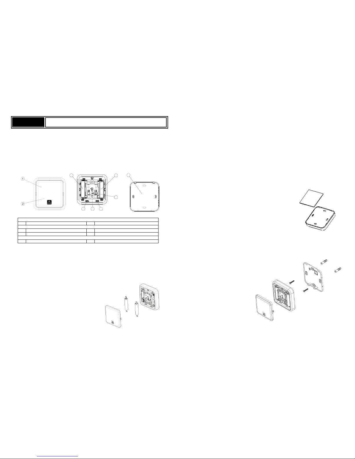
Product Overview
3 3
LINK
4
55
6
7
Front View
Panic ON/OFF Knob Panic
ON/
OFF Knob
Inside View
Battery Compartments
Link Button
Rear Cover Latch
LED Indicator
Rear View
Rear Cover
Adding to Z-WaveTM Network
Auto Inclusion
The detector supports Auto Inclusion feature where it will automatically enter Inclusion mode when first
powered up after a factory reset.
1. Gently lever the bottom edge of the front cover to detach it from the main body.
2. Put a Z-Wave Controller into inclusion mode.
3. Insert 2 AAA-size 1.5V alkaline batteries to battery
compartment with the correct polarity. The LED on
the device should turns ON.
4. The Inclusion process should be completed when the LED turns off.
Note: If Auto Inclusion fails, refer to the Troubleshooting section regarding Manual Inclusion.
Testing
1. For the Panic Button to control other devices on the Z-Wave
TM
controller by 2 seconds long pressing
for Panic and 10 seconds long pressing for disarm, a Scenes needs to be created. Scenes are user
defined elements in controller that determines what actions to take when an event occurs. The
Panic Button creates the event to this Scene which then controls other activation devices such as
plugs or dimmers, or perhaps set the alarm to Arm or Disarm mode.
2. After binding with the Z-Wave
TM
controller, the Panic Button will send data about its battery power to
the Gateway after about 2 minutes. Subsequently it will send the data once the button is pressed..
Installation
The Panic Button can be installed on the wall either by using the supplied double-sided tapes or the
screws:
1. Using the double-sided tape: first peel one side of the tape and place the sticky side onto the back
of the Panic Button. Then peel the other side of the tape and attach the unit onto a proper location
on the wall.
2. Using the screws:
i. Detach the rear cover by removing the front cover and then pressing the rear cover latch
(see item in Product Overview).
ii. Use the rear cover as a template to mark on the wall the positions of two screws. The marks
should be in horizontal positions and the distance between the two marks is 60mm.
iii. Drill the holes using an appropriate size drill bit. Insert the supplied plastic wall plugs first for
a cement wall. For a wooden wall the wall plugs would not be needed.
iv. Position the rear cover on the wall and turn the two screws into the wall (or wall plugs). DO
NOT fasten too tightly as the rear cover might be damaged. Then replace the main body
and the front cover.
Note: Ensure the unit is installed within transmission range of the gateway using the test above.
Page 2
Maintenance
1. Do not put the unit in humid or dusty places or facing direct sunlight.
2. Do not place the unit near combustible substances or any source of heat, e.g. fires, radiators,
boilers etc.
3. The suitable ambient temperature for the unit is -10°C - +40°C.
Low Battery: The Panic Button will inform the Gateway when its battery runs low. Also, if the unit has
completed binding with a Gateway and the front cover is detached, you can see the LED flashes once
when you press the up/down key to indicate low battery condition.
Programming
Z-Wave Group
The unit supports either one of two Z-wave Association Groups:
Group 1: Association with 1 Controller node.
Group 2: Association with 4 nodes (i.e. end devices such as smart plugs and other lighting
controllers).This allows the On/Off module to receive commands directly from these end devices without
the participation of the controller.
Group 1 commands:
When the unit is powered for the first time, the unit will send a Notification Report to the node of
Group 1.
When device status being changed, the unit will send Notification command to the node of Grouping
1.
Upon device status being changed, the unit will check its battery status simultaneously. When the
battery level of the unit drops to an unacceptable level, the unit will emit Notification report to the nodes of
Grouping 1.
Device Reset: When performing Factory Reset the unit will send Device Reset Locally Notification to
the node of Group1.
Group 2 commands:
When device is pressed by Up key, the unit will send BASIC SET command which contains a value
that is adjustable, to the nodes of Grouping 2.
When device is pressed by Down key, the BASIC_SET command will also be sent to the nodes of
Grouping 2.
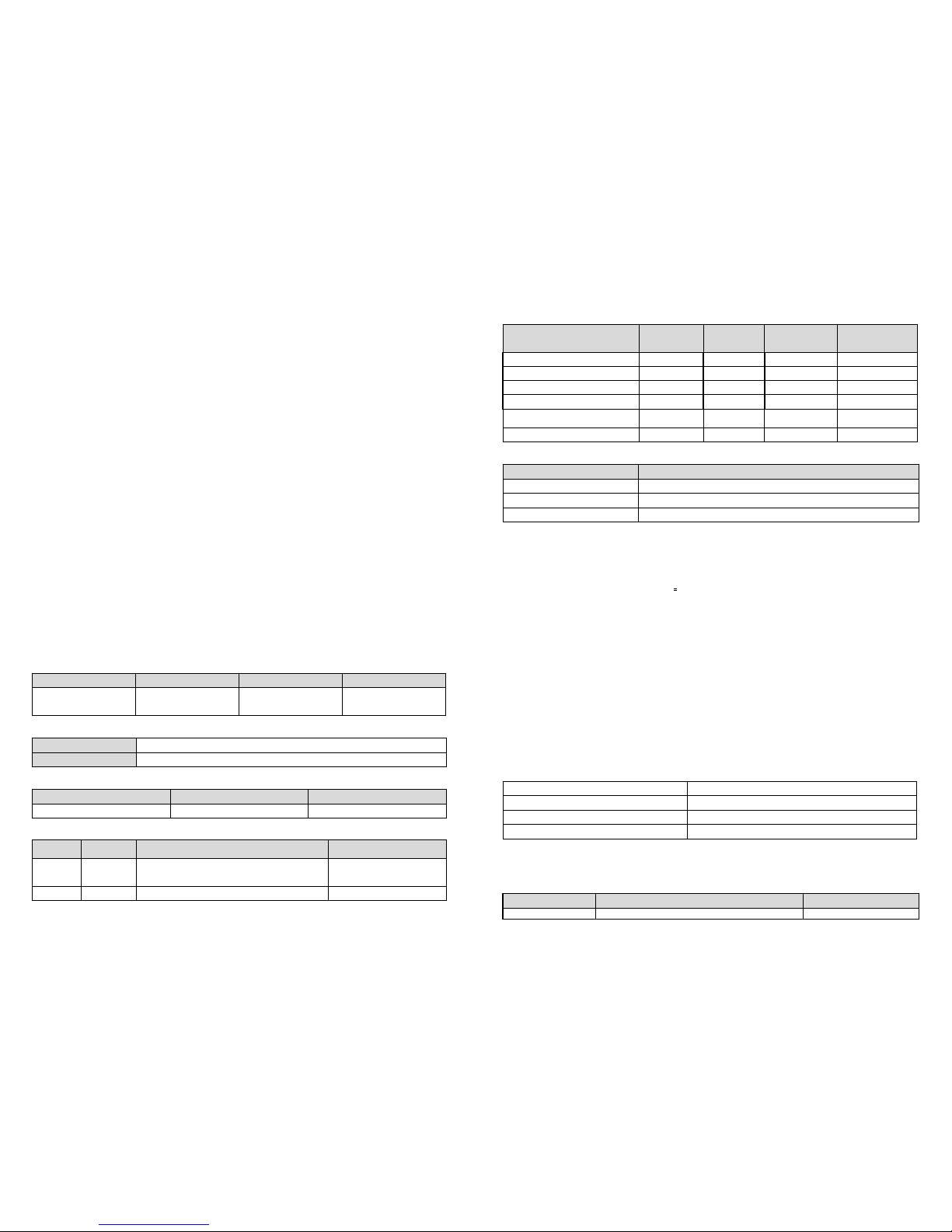
Role Type Node Type Installer Icon User Icon
Slave Sleeping
report
Z-Wave Plus
node
Notification
Sensor
Notification
Sensor
Version
Protocol Library 3 (Slave_Enhance_232_Library)
Protocol Version 4.6 ( 6.71.00)
Manufacturer
Manufacturer ID
Product Type
Product
ID
0x0060
0x000A
0x0002
AGI (Association Group Information) Table
Group Profile Command Class & Command (List) N bytes Group Name(UTF-8)
1 General
Notification Report
Device Reset Locally Notification
Lifeline
2 Control Basic Set Basic Set
Notification
Event Type Event
Event
Parameters
Length
Event
Parameters
Program started
0x0C 0x01 null
Program started
Clear 0x0C 0x00 1
byte 0x01
Program completed
0x0C 0x03 null
Program completed
Clear 0x0C 0x00
1 byte 0x03
The power is applied for the
firs
t time
0x08 0x01 null
The battery is Low
0x08 0x0A null
Battery
Battery Report (value) Description
0x64 Battery is high
0x10 Battery is normal
0x00 Battery is low
Command Classes
COMMAND_CLASS_ZWAVEPLUS_INFO_V2
COMMAND_CLASS_ASSOCIATION_V2 *
COMMAND_CLASS_ASSOCIATION_GRP_INFO *
COMMAND_CLASS_TRANSPORT_SERVICE_V2
COMMAND_CLASS_VERSION_V2 *
COMMAND_CLASS_MANUFACTURER_SPECIFIC_V2*
COMMAND_CLASS_DEVICE_RESET_LOCALLY*
COMMAND_CLASS_POWERLEVEL_V1*
COMMAND_CLASS_BATTERY*
COMMAND_CLASS_SECURITY
COMMAND_CLASS_SECURITY_2
COMMAND_CLASS_NOTIFICATION_V8*
COMMAND_CLASS_WAKE_UP_V2*
COMMAND_CLASS_FIRMWARE_UPDATE_MD_V4 *
*Items marked an asterisk are secure command classes.
Wakeup Command Class
After it has been included into a Z-wave network, the detector will go to sleep but will send a Wakeup
Notification Command periodically at preset period to the controller. The detector will stay awake for 10
seconds at least and then go back to sleep to conserve battery life.
The time interval between Wakeup Notification Commands can be set in the Wakeup Command Class
based on the range values below:
Minimum Wake Up Interval
600s
(10
minutes
)
Maximum Wake Up Interval
86400s (1
day)
Default Wake Up Interval
14400s (4
hours)
Wake Up Interval Step Seconds
600s (10 mi
nutes)
Troubleshooting
The table below lists the several steps involved when adding or removing the detector from the Z-wave
network.
Action/Status Description LED indication
No node ID
The Z-Wave Controller does not allocate a node
2-s
econd on, 2
-
second off
Page 3
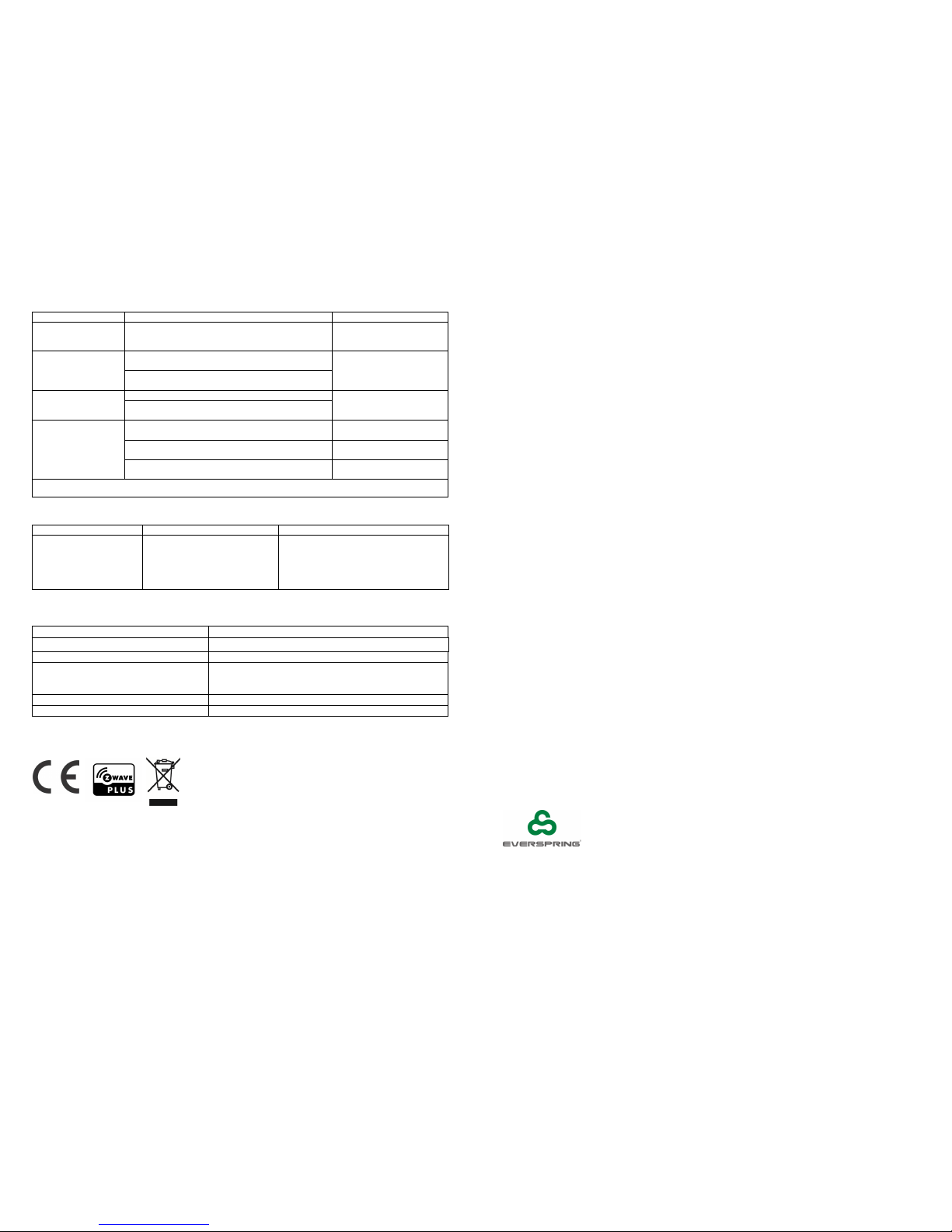
ID to the
unit.
For 2
minutes
Auto Inclusion
The power is applied for the first time and no node
ID has been stored in the module, or after
executing reset.
Manual Inclusion
1. Put the Z-
Wave Controller
into
inclusion mode.
2. Press the
link button
3
times within 1.5 seconds
to put the
unit into inclusion mode
.
Exclusion
1.
Put the Z-
Wave Controller
into exclusion mode.
2.
Press the
link button
3
times within 1.5 seconds
to put the
unit into exclusion mode
.
Factory Reset
(This procedure
should only be used
when the controller
is inoperable.)
1.
Press the
link button
3 times within 1.5 seconds
to put the
unit into exclusion mode
.
2. Within 1 second
of step 1
, press the
link button
again and hold
for
5 sec
onds.
3. Node ID is excluded
. T
he
device reverts to
factory default state
.
2-second on, 2
-
second off
For 2
minutes
Failed or successful results in including/excluding the ID can be viewed on the Z-Wave Controller.
Table below lists typical problems encountered:
Symptom
Possible Cause
Recommendation
Press
Panic Button
,
LED illuminates, but the
receiver(s) have no
response
1. Distance between the
Panic Button and the
receiver(s) too far
2. Battery running low
3. Receivers did not learn ID
successfully
1. Move closer to the receivers
2. Replace new batteries
3. Bind with Gateway again
Specifications
Battery Type AAA Battery x2
Battery Life 1 year*
Transmitting Range Up to 100 meters line of sight
Frequency Range EU: 868.42HMz
US: 908.42 MHz
JP: 922.5MHz
FCC ID FU5AC136
IC 23210-AC136
Specifications are subject to change without notice
*measured at 1 trigger per day
Federal Communication Commission Interference Statement
This device complies with Part 15 of the FCC Rules. Operation is subject to the following two conditions:
(1) This device may not cause harmful interference, and (2) this device must accept any interference
received, including interference that may cause undesired operation.
This equipment has been tested and found to comply with the limits for a Class B digital device, pursuant
to Part 15 of the FCC Rules. These limits are designed to provide reasonable protection against
harmful interference in a residential installation. This equipment generates, uses and can radiate radio
frequency energy and, if not installed and used in accordance with the instructions, may cause harmful
interference to radio communications. However, there is no guarantee that interference will not occur in
a particular installation. If this equipment does cause harmful interference to radio or television
reception, which can be determined by turning the equipment off and on, the user is encouraged to try to
correct the interference by one of the following measures:
- Reorient or relocate the receiving antenna.
- Increase the separation between the equipment and receiver.
- Connect the equipment into an outlet on a circuit different from that
to which the receiver is connected.
- Consult the dealer or an experienced radio/TV technician for help.
FCC Caution: Any changes or modifications not expressly approved by the party responsible for
compliance could void the user's authority to operate this equipment.
This transmitter must not be co-located or operating in conjunction with any other antenna or transmitter.
Radiation Exposure Statement:
This equipment complies with FCC radiation exposure limits set forth for an uncontrolled environment.
This equipment should be installed and operated with minimum distance 20cm between the radiator &
your body.
Industry Canada statement:
This device complies with ISED’s licence-exempt RSSs. Operation is subject to the following two
conditions: (1) This device may not cause harmful interference, and (2) this device must accept any
interference received, including interference that may cause undesired operation.
Le présent appareil est conforme aux CNR d’ ISED applicables aux appareils radio exempts de licence.
L’exploitation est autorisée aux deux conditions suivantes : (1) le dispositif ne doit pas produire de
brouillage préjudiciable, et (2) ce dispositif doit accepter tout brouillage reçu, y compris un brouillage
susceptible de provoquer un fonctionnement indésirable.
Radiation Exposure Statement:
This equipment complies with ISED radiation exposure limits set forth for an uncontrolled environment.
This equipment should be installed and operated with minimum distance 20cm between the radiator &
your body.
Déclaration d'exposition aux radiations:
Cet équipement est conforme aux limites d'exposition aux rayonnements ISED établies pour un
environnement non contrôlé. Cet équipement doit être installé et utilisé avec un m inimum de 20 cm de
distance entre la source de rayonnement et votre corps.
Warning:
Do not dispose of electrical appliances as unsorted municipal waste, use separate collection facilities.
Contact your local government for information regarding the collection systems available.
If electrical appliances are disposed of in landfills or dumps, hazardous substances can leak into the
groundwater and get into the food chain, damaging your health and well-being.
When replacing old appliances with new ones, the retailer is legally obligated to take back your old
appliance for disposal at least for free of charge.
www.everspring.com
50 Sect. 1 Zhonghua Rd Tucheng
NewTaipeiCity 236 Taiwan..
A501112653R01
 Loading...