

Everpure Coldrink series, Coldrink 1, Coldrink 3, Coldrink 2 User Manual
EVERPURE
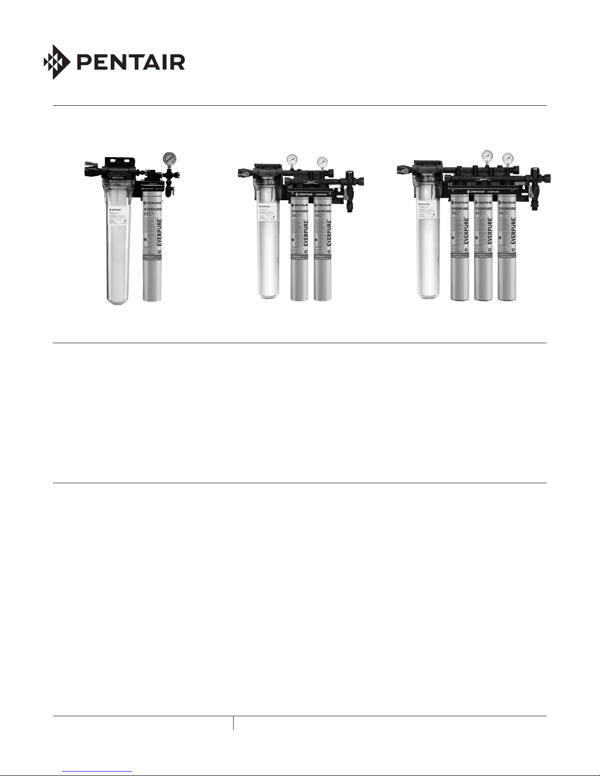
Figure 1 Coldrink 1 System Figure 2 Coldrink 2 System Figure 3 Coldrink 3 System
®
COLDRINK® SERIES FILTER SYSTEMS
SELECT A MOUNTING LOCATION
1. Give consideration to the weight of the unit when
operating (filled with water). Operating weights of the
Coldrink Systems are:
• System 1 - 19 lbs (8.62 kg)
• System 2 - 35 lbs (15.9 kg)
• System 3 - 45 lbs (20.4 kg)
INSTALLATION
1. Use the predrilled mounting holes in the manifold
bracket as guides. Mark and drill anchor holes. Mount
securely. See Figures 4-6.
2. Shut off power to equipment.
3. Connect outlet port of Coldrink System to equipment
served. Always use a NSF approved pipe dope or
plumber tape at all connections. Use a backup wrench
on all fittings while connecting to avoid excessive stress
on the system components.
4. Install a manual shut-off valve leading to the system
for servicing.
5. Connect minimum 3/8” water line to the Coldrink 1
System inlet. Use a minimum 1/2” for Coldrink 2
and 3 Systems.
6. Connect tubing to flushing valve and run to drain. The
cross fitting has a flushing valve installed on the bottom.
2. The location should allow for:
• Minimum clearance of 2-1/2” (6.4 cm) under the
cartridge(s) so it can be lowered for removal
and replacement.
• Adequate space for “in” and “out” water
line connections.
• Be near a drain for flushing and near a 110V outlet
if the accessory (sold separately) EverguardTM Low
Pressure Alarm is used. See Figures 1-6.
NOTE: Some municipal plumbing codes and good
sanitary practices require an air gap at the drain
termination point.
7. Shut off the system inlet valve located on the inlet of the
prefilter head.
8. Check to be sure the o-ring on the prefilter housing is
sufficiently lubricated. Use a good grade of silicone
lubricant, if needed. Position the EC210 Prefilter
Cartridge on guide seat in the bottom of the bowl. Then
thread the bowl into the head by hand. Use a sump
wrench to snug the bowl onto the head.
9. Install the carbon filter cartridge(s) into the filter head(s)
following directions on the cartridge label or as shown in
the Cartridge Change Change Procedure
section illustrations.
10. Turn on inlet water to the filter system and check
for leaks.
FILTRATION & PROCESSING SOLUTIONS
COLD RI NK SERIES INSTAL LAT ION AND OPERAT IO N GUIDE
1
21.5"
11. Open the flushing valve and flush the cartridge(s) by
running water through at full force for five (5) minutes.
This will set the filtering media and purge any air and
fines, insuring maximum filter life. See illustrations.
12. After flushing, close the flushing valve, turn on power
to equipment, and plug the LPA (if so equipped) into the
electrical outlet. The system is ready for operation.
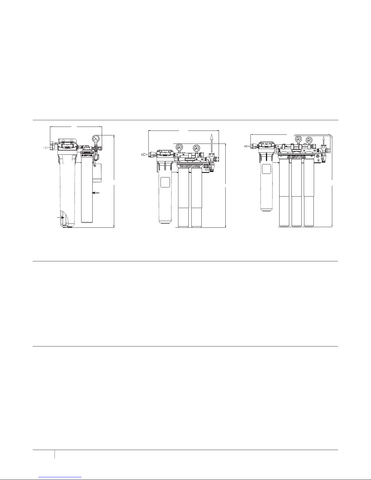
DIMENSIONS
14"
INLET
3/8" FNPT
INLET
3/4" FNPT
Check for compliance with state and local laws and regulations. Do not use with water that is microbiologically unsafe
or of unknown quality without adequate disinfection before or
after the system. Systems certified for cyst reduction may be
used on disinfected waters that may contain filterable cysts.
For installations in Massachusetts, the Commonwealth of
Massachusetts Plumbing Code 248 CMR shall be adhered to.
Consult your licensed plumber for installation of the system.
This system and its installation must comply with state and
local regulations.
OUTLET
3/4" FNPT
INLET
3/4" FNPT
25.75"
Outlet
3/4" FNPT
Prefilter
(Inside Sump)
Figure 4 – Coldrink 1
Primary
Filter
Cartridge
25"
Figure 5 – Coldrink 2
25.59"
Figure 6 – Coldrink 3
29.59"
FLUSHING
For maximum life, all carbon filter cartridges must be flushed for five (5) minutes at full flow before use.
ALL NEW CARTRIDGES MUST BE FLUSHED AFTER EACH CARTRIDGE CHANGE BEFORE BEING PUT INTO SERVICE!
If the cartridges are new, have been properly flushed and both needle and follower register inadequate pressure, or the LPA
is sounding, you may be experiencing inadequate water pressure or some restriction may exist in the inlet water line. In either
case, the incoming water pressure must be improved to receive optimum filter life.
COMPLETE CARTRIDGE CHANGE INSTRUCTIONS CAN BE FOUND ON THE FILTER CARTRIDGE LABEL.
Not for residential use. For food service applications only.
CARTRIDGE CHANGE DETERMINATION
Replace the prefilter cartridge whenever it becomes excessively dirty (observed visually or by flow restriction). Follow the
change instructions provided with the cartridge. Replace carbon filter cartridges when capacity is reached, or when flow
becomes inadequate, but at least annually. All carbon filter cartridges on multiple cartridge systems should be changed at
the same time. The system pressure gauge or accessory (sold separately) EverguardTM Low Pressure Alarm (LPA) provide
quick, simple means of determining when the filter cartridge(s) should be checked. Installed on the system outlet manifold,
the gauge or LPA can be used to monitor both dynamic (flowing) and static (line) pressure. The cartridge(s) should be changed
when the pressure gauge needle is in the red area while equipment is in operation, and yet the needle shows adequate line
pressure between cycles. Observe the needle during the next equipment on cycle. If the needle registers adequate pressure,
it can be assumed that the temporary low-pressure condition was caused by a brief power failure or other incoming pressure
disruption. If the low pressure condition is not due to an external condition, check/change the prefilter first. If the low pressure
condition is still not corrected, change the carbon filter cartridges.
2 COLD RI NK SERIES INSTAL LAT ION AND OPERAT IO N GUIDE
 Loading...