

Page 1
EVERPURE
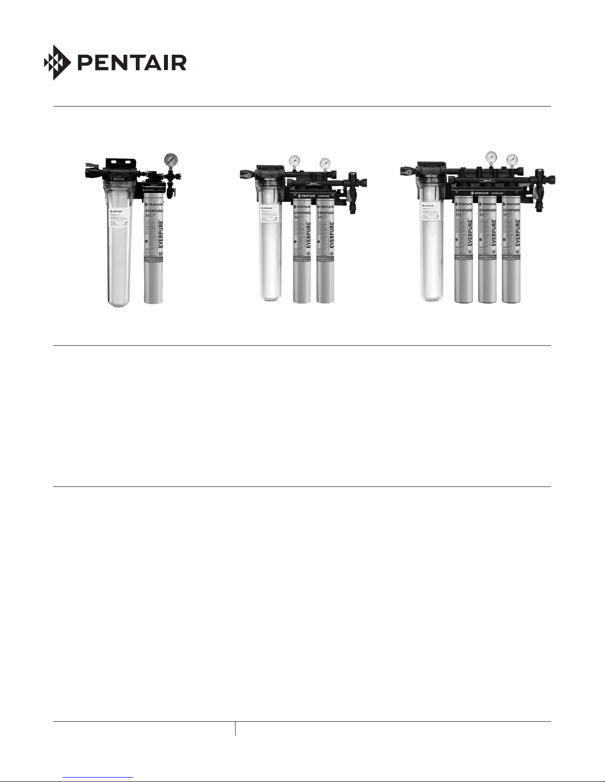
Figure 1 Coldrink 1 System Figure 2 Coldrink 2 System Figure 3 Coldrink 3 System
®
COLDRINK® SERIES FILTER SYSTEMS
SELECT A MOUNTING LOCATION
1. Give consideration to the weight of the unit when
operating (filled with water). Operating weights of the
Coldrink Systems are:
• System 1 - 19 lbs (8.62 kg)
• System 2 - 35 lbs (15.9 kg)
• System 3 - 45 lbs (20.4 kg)
INSTALLATION
1. Use the predrilled mounting holes in the manifold
bracket as guides. Mark and drill anchor holes. Mount
securely. See Figures 4-6.
2. Shut off power to equipment.
3. Connect outlet port of Coldrink System to equipment
served. Always use a NSF approved pipe dope or
plumber tape at all connections. Use a backup wrench
on all fittings while connecting to avoid excessive stress
on the system components.
4. Install a manual shut-off valve leading to the system
for servicing.
5. Connect minimum 3/8” water line to the Coldrink 1
System inlet. Use a minimum 1/2” for Coldrink 2
and 3 Systems.
6. Connect tubing to flushing valve and run to drain. The
cross fitting has a flushing valve installed on the bottom.
2. The location should allow for:
• Minimum clearance of 2-1/2” (6.4 cm) under the
cartridge(s) so it can be lowered for removal
and replacement.
• Adequate space for “in” and “out” water
line connections.
• Be near a drain for flushing and near a 110V outlet
if the accessory (sold separately) EverguardTM Low
Pressure Alarm is used. See Figures 1-6.
NOTE: Some municipal plumbing codes and good
sanitary practices require an air gap at the drain
termination point.
7. Shut off the system inlet valve located on the inlet of the
prefilter head.
8. Check to be sure the o-ring on the prefilter housing is
sufficiently lubricated. Use a good grade of silicone
lubricant, if needed. Position the EC210 Prefilter
Cartridge on guide seat in the bottom of the bowl. Then
thread the bowl into the head by hand. Use a sump
wrench to snug the bowl onto the head.
9. Install the carbon filter cartridge(s) into the filter head(s)
following directions on the cartridge label or as shown in
the Cartridge Change Change Procedure
section illustrations.
10. Turn on inlet water to the filter system and check
for leaks.
FILTRATION & PROCESSING SOLUTIONS
COLD RI NK SERIES INSTAL LAT ION AND OPERAT IO N GUIDE
1
Page 2
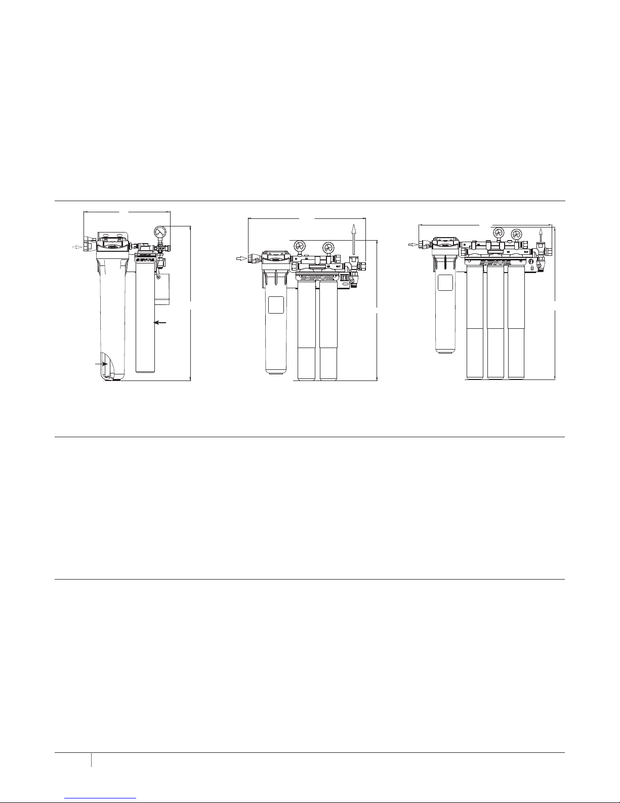
21.5"
11. Open the flushing valve and flush the cartridge(s) by
running water through at full force for five (5) minutes.
This will set the filtering media and purge any air and
fines, insuring maximum filter life. See illustrations.
12. After flushing, close the flushing valve, turn on power
to equipment, and plug the LPA (if so equipped) into the
electrical outlet. The system is ready for operation.
DIMENSIONS
14"
INLET
3/8" FNPT
INLET
3/4" FNPT
Check for compliance with state and local laws and regulations. Do not use with water that is microbiologically unsafe
or of unknown quality without adequate disinfection before or
after the system. Systems certified for cyst reduction may be
used on disinfected waters that may contain filterable cysts.
For installations in Massachusetts, the Commonwealth of
Massachusetts Plumbing Code 248 CMR shall be adhered to.
Consult your licensed plumber for installation of the system.
This system and its installation must comply with state and
local regulations.
OUTLET
3/4" FNPT
INLET
3/4" FNPT
25.75"
Outlet
3/4" FNPT
Prefilter
(Inside Sump)
Figure 4 – Coldrink 1
Primary
Filter
Cartridge
25"
Figure 5 – Coldrink 2
25.59"
Figure 6 – Coldrink 3
29.59"
FLUSHING
For maximum life, all carbon filter cartridges must be flushed for five (5) minutes at full flow before use.
ALL NEW CARTRIDGES MUST BE FLUSHED AFTER EACH CARTRIDGE CHANGE BEFORE BEING PUT INTO SERVICE!
If the cartridges are new, have been properly flushed and both needle and follower register inadequate pressure, or the LPA
is sounding, you may be experiencing inadequate water pressure or some restriction may exist in the inlet water line. In either
case, the incoming water pressure must be improved to receive optimum filter life.
COMPLETE CARTRIDGE CHANGE INSTRUCTIONS CAN BE FOUND ON THE FILTER CARTRIDGE LABEL.
Not for residential use. For food service applications only.
CARTRIDGE CHANGE DETERMINATION
Replace the prefilter cartridge whenever it becomes excessively dirty (observed visually or by flow restriction). Follow the
change instructions provided with the cartridge. Replace carbon filter cartridges when capacity is reached, or when flow
becomes inadequate, but at least annually. All carbon filter cartridges on multiple cartridge systems should be changed at
the same time. The system pressure gauge or accessory (sold separately) EverguardTM Low Pressure Alarm (LPA) provide
quick, simple means of determining when the filter cartridge(s) should be checked. Installed on the system outlet manifold,
the gauge or LPA can be used to monitor both dynamic (flowing) and static (line) pressure. The cartridge(s) should be changed
when the pressure gauge needle is in the red area while equipment is in operation, and yet the needle shows adequate line
pressure between cycles. Observe the needle during the next equipment on cycle. If the needle registers adequate pressure,
it can be assumed that the temporary low-pressure condition was caused by a brief power failure or other incoming pressure
disruption. If the low pressure condition is not due to an external condition, check/change the prefilter first. If the low pressure
condition is still not corrected, change the carbon filter cartridges.
2 COLD RI NK SERIES INSTAL LAT ION AND OPERAT IO N GUIDE
Page 3

REPLACEMENT PARTS
Contact your local Pentair® Everpure® dealer for system
replacement parts.
DESCRIPTION PART NUM BER
Outlet Pressure Gauge EV3114-09
Inlet Pressure Gauge
(Coldrink 3 & 4)
EV3114-09
Inlet/flushing Valve EV3114-07
O-ring for Prefilter EV3112-40
Prefilter Bowl EV3112-38
PRESSURE GAUGES
System Tested and Certified by NSF International against NSF/ANSI
Standard 42 and 53 for the reduction of:
Standard No. 42 —
Aesthetic Effects
Bacteriostatic Effects
(MC2 and XC2 only)
Chemical Reduction
Standard No. 53 —
Health Effects
Mechanical Filtration
Cyst (MC, MC2, XC, XC2 only)
Asbestos (MC and MC2 only)
Taste and Odor
Chlorine
Mechanical Filtration
Nominal Particulate Class I
(MC, MC2, XC, XC2 only)
Low Inlet
Pressure
CARTRIDGE CHANGE PROCEDURE
E-Series Pre filter Cartri dge Change
1. Shut of f power t o equipment . Shut off
inlet w ater ahea d of syste m.
Everpure Carbo n Filter Cartridge
Change
1. Shut of f power to eq uipment. S hut off
inlet w ater ahea d of syste m.
2. Push re d relief v alve. Unsc rew bowl .
Remov e prefilt er cartr idge.
2. Open fl ushing val ve to relie ve press ure.
3. Hold he ad firmly an d push upwa rd. Turn
cart ridge to le ft until i t stops.
Adequate Inlet
Pressure
3. Clean b owl wit h filtered w ater only ; NO
SPECIAL CLEANERS.
4. Feel he ad o-ring. I f dry, lubr icate wit h
high qua lity sil icone lubr icant.
4. Pull ca rtridg e downwar d and out of he ad.
5. Hold he ad firmly. A lign cart ridge lug w ith
label . Insert n ew cartr idge firm ly
into he ad.
Low Outlet
Pressure
5. Inst all new pre filter car tridge in b owl.
Hand ti ghten bow l onto head .
6. Turn car tridge ri ght 90˚ unti l
rota tion stop s.
7. Repea t steps 3-6 f or remaini ng
cartridges.
Adequate Outlet
Pressure
6. Turn on wa ter. Turn on pow er to
equipment.
Flushing
8. With f lushing v alve fully o pen, open in let
wate r at full for ce for five m inutes. C lose
flus hing valve .
9. Turn on po wer to equi pment
3 COLD RI NK SERIES INSTAL LAT ION AND OPERAT IO N GUIDE
Page 4

OPERATING SPECIFICATIONS
COMBINED MODEL NAME REPLACEMENT CARTRIDGE
FLOW RATE CAPACITY
GPM LPM GALLONS LITRES
Coldrink System 1 - MC MC 1.67 6.3 9,000 34,000
Coldrink System 1 - MC
2
MC
2
1.67 6.3 12,000 45,420
Coldrink System 1 - XC XC 1.67 6.3 12,000 45,420
Coldrink System 1 - XC
2
XC
2
1.67 6.3 12,000 45,420
Coldrink System 1 - 4CB5 4CB5 1.67 6.3 6,000 22,710
Coldrink System 1 - 7CB5 7CB5 2.5 9.4 10,000 67,850
Coldrink System 2 - MC MC 3.3 12.6 18,000 68,000
Coldrink System 2 - MC
2
MC
2
3.3 12.6 18,000 68,000
Coldrink System 2 - XC XC 3.3 12.6 24,000 90,840
Coldrink System 2 - XC
2
XC
2
3.3 12.6 24,000 90,840
Coldrink System 2 - 4CB5 4CB5 3.3 12.6 12,000 45,420
Coldrink System 2 - 7CB5 7CB5 5.0 18.9 20,000 75,700
Coldrink System 3 - MC MC 5.0 18.9 27,000 102,000
Coldrink System 3 - MC
2
MC2 5.0 18.9 27,000 102,000
Coldrink System 3 - XC XC 5.0 18.9 36,000 136,260
Coldrink System 3 - XC
2
XC
2
5.0 18.9 36,000 136,260
Coldrink System 3 - 4CB5 4CB5 5.0 18.9 18,000 68,000
Coldrink System 3 - 7CB5 7CB5 7.5 28.2 30,000 113,550
* For individual cartridge specifications, refer to cartridge literature.
Temperature
35-100°F (2-38°C)
Pressure
10-125 psi (0.7-8.6 bar), non-shock
For cold water use only.
The term ‘bacteriostatic’ indicates that the system limits the passage or growth of bacteria that may already exist in the
incoming water. It does not mean that the water leaving the system is safer to drink than the water entering the system.
EPA Est. No. 002623-IL-002
FILTRATION & PROCESSING SOLUTIONS
EVERPURE-SHURFLO WORLD HEADQUARTERS, 1040 MUIRFIELD DRIVE, HANOVER PARK, IL 60133 USA • WWW.EVERPURE.COM
800.942.1153 MAIN (US ONLY) • 800.942.1153 (US ONLY) • 630.307.3000 MAIN • 630.307.3030 FAX • CSEVERPURE@PENTAIR.COM EMAIL
PENTAIR AUSTALIA/NEW ZEALAND, 1-21 MONASH DRIVE, DANDENONG SOUTH, VIC 3175, AUSTRALIA
1300.576.190 TEL • AU.EVERPURE@PENTAIR.COM EMAIL
EVERPURE-SHURFLO CHINA, 21F CLOUD 9 PLAZA , NO 1118, SHANGHAI , 200052, CHINA
86.21.3211.4588 TEL • 86.21.3211.4580 FAX • CHINA.WATER@PENTAIR.COM EMAIL
EVERPURE-SHURFLO INDIA, G REEN BOULEVARD, B-9/A, 7TH FLOOR - TOWER B SECTO R 62, NO IDA - 201301
91.120.419.9444 TEL • 91.120.419.9400 FAX • INDIACUSTOMER@PENTAIR.COM EMAIL
EVERPURE-SHURFLO EUROPE, PENTAIR WATER BELGIUM BVBA, INDUS TRIEPARK WOL FSTEE, TOEKOMSTLAAN, 30 B-2 200 HERENTALS, BELGI UM
+32.(0).14.283.500 TEL • +32.(0).14.283.505 FAX • SALES@EVERPURE-EUROPE.COM EMAIL
EVERPURE-SHURFLO JAPAN INC., HASHIMOTO MN BLDG. 7F, 3-25-1 HASHIMOTO, MIDORI-KU, SAGAMIHARA-SHI KANAGAWA 252-0143, JAPAN
81.(0)42.775.3011 TEL • 81.(0)42.775.3015 FAX • INFO@EVERPURE.CO.JP EMAIL
EVERPURE-SHURFLO SOUTHEAST ASIA, 390 HAVE LOCK ROAD, #04-01, KI NG’S CE NTRE, SINGA PORE 169662
65.6795.2213 TEL • FAX: 65.6795.2219 FAX • CSEVERPURE@PENTAIR.COM EMAIL
All Pentair trademarks and logos are owned by Pentair, Inc. or its affiliates. All other registered and unregistered trademarks and logos are the property of their
respective owners. Because we are continuously improving our products and services, Pentair reserves the right to change specifications without prior notice.
Pentair is an equal opportunity employer.
© 2014 Pentair Filtration Solutions, LLC. All Rights Reserved.
EV3112-79 Rev G MY14
 Loading...