

Ever Power Systems POWERLINE RT-6000, POWERLINE RT-10000 Instruction Manual

EVER UPS POWERLINE RT 6000 / 10000 series instruction manual
2017-01-05 13:16
Technical Support, tel.: +48 61 6500 400
www.ever.eu
2
TABLE OF CONTENTS
INTRODUCTION ................................................................................................................................................. 3
GENERAL FEATURES OF THE UPS UNIT ................................................................................................... 3
SAFETY INSTRUCTIONS AND RECOMMENDATIONS ............................................................................ 5
UPS DESCRIPTION AND INSTALLATION ................................................................................................. 11
GENERAL INFORMATION .......................................................................................................................... 11
UNPACKING THE PRODUCT ...................................................................................................................... 12
ELEMENTS OF THE UPS - REAR PANEL .................................................................................................. 15
HOW IT WORKS ............................................................................................................................................ 17
OPERATION MODES AND WARNINGS .................................................................................................... 22
RACK VERSION UPS INSTALLATION ...................................................................................................... 24
Installation of the UPS unit and the battery module in a rack......................................................................25
Installation of battery modules .....................................................................................................................27
TOWER VERSION UPS INSTALLATION ................................................................................................... 29
CONNECTING POWER SUPPLY LEADS AND START-UP ...................................................................... 30
PARALLEL OPERATION .............................................................................................................................. 34
DESCRIPTION OF OPERATION OF THE POWER SUPPLY UNIT ........................................................ 38
SWITCHING THE UPS ON AND OFF .......................................................................................................... 38
CONTROL PANEL AND LCD DISPLAY FUNCTIONS ‑ MENU STRUCTURE ...................................... 39
SAFEGUARDS ................................................................................................................................................ 49
EPO .................................................................................................................................................................. 50
COMMUNICATION WITH PC ....................................................................................................................... 50
NETWORK CARDS (AVAILABLE OPTIONALLY) ................................................................................... 51
SOFTWARE FOR MANAGING THE UPS UNIT ......................................................................................... 52
OPERATING INSTRUCTIONS ....................................................................................................................... 53
TRANSPORTING THE UPS UNIT ................................................................................................................ 53
MAINTENANCE OF THE UPS UNIT AND BATTERIES ........................................................................... 53
BATTERY HOT SWAP .................................................................................................................................. 53
TESTING BATTERIES ................................................................................................................................... 55
STORING THE UPS UNIT AND THE BATTERIES .................................................................................... 55
DISPOSING OF THE USED BATTERIES OR THE UPS UNIT .................................................................. 56
TECHNICAL PARAMETERS .......................................................................................................................... 57
TROUBLE SHOOTING .................................................................................................................................... 59
LEGAL REGULATIONS AND WARRANTY ................................................................................................ 63
DECLARATION OF CONFORMITY ............................................................................................................ 63
WARRANTY ................................................................................................................................................... 63

EVER UPS POWERLINE RT 6000 / 10000 series instruction manual
3
www.ever.eu
Pomoc Techniczna, tel.: +48 61 6500 400
2017-01-05 13:16
INTRODUCTION
Thank you for purchasing the EVER POWERLINE RT UPS. Please read the
instruction manual before you begin using the device. This manual contains all
relevant information to ensure correct and safe operation of the unit. Please read
this manual carefully and thoroughly prior to using the EVER POWERLINE RT. This
will help to operate the unit and correctly and safely. This EVER POWERLINE RT
UPS system has been designed and engineered to provide the highest standard of
protection against power failure. We hope that the purchased UPS will meet your
expectations.
A series of hi-tech, on-line (VFI) UPS units (uninterruptible power system), designed
with double conversion topology, for excellent protection of the connected receivers.
The UPS protects sensitive equipment and systems from common problems such as
power outages, drops and interruptions in the mains, surges and other faulty
conditions in the power supply line.
EVER POWERLINE RT series UPS units are mainly used with network devices,
servers, workstations and other electric, electronic and IT devices.
GENERAL FEATURES OF THE UPS UNIT
Alongside their excellent performance and reliability, the POWERLINE RT range of
UPS units offers a number of other advantages which include:
On-line real double conversion and sine wave output voltage.
Dynamic cooling management algorithm designed to allow adaptive adjustment
of the cooling system capacity to the current state of the UPS unit (to minimize
power losses and to reduce the costs associated with the demand for cooling).
The Intelligent Battery Management technology utilizes the advanced battery
management strategy in order to extend battery life and to optimize the charging
time and charging energy efficiency.
Possibility of selection of high performance operation (ECO).
The Start-on-battery function allows running the UPS even if there is no power
in the mains (so-called "cold start").
VFI (ONLINE) topology UPS with external batteries.

EVER UPS POWERLINE RT 6000 / 10000 series instruction manual
2017-01-05 13:16
Technical Support, tel.: +48 61 6500 400
www.ever.eu
4
Scalability (extension) of autonomous operation time thanks to the ability of
connecting more battery modules to the UPS (up to 4 units - optional).
Remote Emergency Power Off (Remote EPO) functionality which interrupts
power supply from the UPS output to loads in extreme situations or in
emergency (e.g. fire).
Wide range of input voltage.
Easier handling thanks to the safe procedure of battery replacement, without
having to switch off the UPS power supply.
Users can choose to install the unit in one of the two variants: Rack or Tower.
Optional rail guides for rack enclosures.
Compact size (excellent power to size ratio).
Output connectors in two versions: power supply strip and IEC sockets with
loads of 10 A and 16 A.
I/O connections strip configured by default with bypass for service purposes.
Standard communication functions: an RS 232 communication port, a USB
communication port.
Optional extension cards provide additional communication functionalities.
Easy firmware update, without the need of professional assistance.

EVER UPS POWERLINE RT 6000 / 10000 series instruction manual
5
www.ever.eu
Pomoc Techniczna, tel.: +48 61 6500 400
2017-01-05 13:16
SAFETY INSTRUCTIONS AND RECOMMENDATIONS
A) General information
CAUTION! Before starting the procedures described in this manual,
please read the general safety instructions (including the instructions
found in this document), health & safety information, environmental
protection information and legal regulations that may apply. Always
observe the instructions and recommendations found in these
documents.
CAUTION! It is strictly forbidden for the user to perform any repairs, as
this would constitute a health hazard and may result in death. Any
repairs and replacement of batteries should be carried out only by
suitably qualified service technicians, with professional licences required
by law.
CAUTION! The unit should be operated and stored in conditions
complying with the requirements set in the specification (technical
documentation).
CAUTION! The UPS is disconnected from the mains only when the
power lead is disconnected removed from the mains socket.
CAUTION! The unit is equipped with an internal power source (batteries)
or it may operate in combination with a fixed, external source of power
(battery packs). Dangerous voltage may be present at the output
terminal(s), even if the unit has been disconnected from the mains.
CAUTION! The user should place warning labels on all remotely
installed primary isolation switches in order to warn electrical service
technicians that the circuit is powered by a UPS unit. The following (or
equivalent) text should be used on such warning labels:
DISCONNECT THE UPS SYSTEM BEFORE STARTING WORK ON THIS
CIRCUIT.
EVER UPS POWERLINE RT 6000 / 10000 series instruction manual
2017-01-05 13:16
Technical Support, tel.: +48 61 6500 400
www.ever.eu
6
CAUTION! Opening the unit’s casing may result in electric shock.
CAUTION! Do not touch any electrical connectors, terminals and internal
metal elements unless power supply has been properly disconnected.
CAUTION! All openings and spaces designed to provide access to the
unit's electrical connections must remain covered (with applicable
covers). Failure to observe this requirement may create hazard
potentially resulting in injury or death for persons who touch such
connectors. It may also cause damage to the unit.
CAUTION! In the event of a short circuit, the resulting high current may
cause serious burns or scalds.
CAUTION! There are no user-serviceable parts inside the UPS unit.
CAUTION! The POWERLINE RT range of UPS units is not intended to
work directly with medical equipment, life-supporting equipment or any
other equipment that may have effect on health.
B) Installation information and requirements
CAUTION! The POWERLINE RT range of UPS units may only be
installed and maintained by suitably qualified service technicians.
CAUTION! Before installation of the UPS unit, the staff and users must
become familiar with the Health and Safety regulations when working
and handling electrical equipment up to 1 kV voltage.
CAUTION! Before connecting any cables or making any connections
within the UPS unit or in the electrical system, make sure there is no
dangerous voltage on electrical terminals and cables in the system.
EVER UPS POWERLINE RT 6000 / 10000 series instruction manual
7
www.ever.eu
Pomoc Techniczna, tel.: +48 61 6500 400
2017-01-05 13:16
CAUTION! The UPS may only be connected to a power system with
indicated rated voltage, with a suitable grounding connection installed.
The facility's electrical system to which the UPS unit is connected must
be fitted with overload and short-circuit protection.
CAUTION! Only TN-S or TN-C-S configuration is allowed on the UPS
unit's input side, and only TN-S configuration is allowed on the UPS
unit's output side.
CAUTION! No extension cords should be used for connecting the UPS
unit.
CAUTION! Installing a UPS unit in proximity of flammable materials or
substances is strictly prohibited!
Technicians must not work alone in hazardous conditions that may be dangerous
to health and/or life.
Shortly after the UPS unit has been moved from a cold environment to a warm
environment, moisture condensation may appear. The UPS unit must be
completely dry before installation and operation. The acclimatization time should
be at least 2 hours.
UPS units and battery packs must not be installed in humid environment.
UPS units and battery packs must not be installed in places where they would be
exposed to direct sunlight. They must not be installed near sources of heat.
Ventilation openings in the UPS unit casing must not be blocked. Always observe
distances to ventilation openings specified in the manual.
Before connecting the units, is necessary to check the condition of all leads,
cables, connectors, sockets and plugs, as well as that of the unit itself.
The unit must be connected to a power circuit with a PE grounding conductor.
Failure to observe this requirement may result in electric shock.
To reduce the risk of electric shock (in case the grounding cannot be checked),
the unit must be disconnected from the mains before installation or connecting to
other equipment. The power lead may only be connected again after making all
required connections.

EVER UPS POWERLINE RT 6000 / 10000 series instruction manual
2017-01-05 13:16
Technical Support, tel.: +48 61 6500 400
www.ever.eu
8
The electric system's grounding conductor leads the leakage current away from
the receivers. The leakage currents of all loads connected to the UPS unit's
output are combined in the UPS unit's power lead. The summary leakage current
may trigger protective devices (RCD) and result in disconnecting power to the
loads.
A UPS unit is a fixed connection device; consequently, a breaker should be used
in the fixed cabling.
When connecting and disconnecting signal cables, all actions should be
performed with one hand only (if feasible). This is to avoid electric shock when
touching two surfaces with different electrical potentials.
Connecting leads should be placed so that people walking over them will not step
or trip on them.
An emergency power-off button (EPO), dedicated to the UPS system, should be
installed in the building's electrical system. This is to allow disconnecting, in
emergency, the UPS unit from the connected loads regardless of the mode in
which the UPS is operating.
To minimise the risk of fire, connections should only be made to circuits (electrical
systems) whose rating is adequate for the connected loads, with properly selected
overcurrent protection. Additionally, the breaker should feature at least a 3 mm
insulating air gap.
C) Operation of the UPS unit
Health and Safety regulations and guidelines specified in the UPS unit operating
manual must be observed when handling and operating the UPS unit.
All these instructions must be executed step by step. If any problems emerge
when executing the instructions given in this document, please contact EVER
service support (www.ever.eu).
Never disconnect the grounding at the UPS unit or at the terminals of the
building's electrical system, as this will disable the UPS unit's protective
grounding.
There may be voltage on the UPS unit's output terminals, even if the UPS is
disconnected from the building's electrical system (due to presence of power in
the unit's internal batteries and/or battery packs).
Liquids and foreign bodies must not be allowed to penetrate the UPS casing.

EVER UPS POWERLINE RT 6000 / 10000 series instruction manual
9
www.ever.eu
Pomoc Techniczna, tel.: +48 61 6500 400
2017-01-05 13:16
WARNING: This is a C3 category UPS. For commercial and industrial use in
secondary environment. Additional precautions or limitations in installation may be
required to prevent the emission of interferences.
D) Maintenance, repair and breakdown information
Dangerously high voltages are present in the UPS unit. Only qualified service
technicians may perform maintenance works.
CAUTION - Risk of electric shock! Even if the unit has been disconnected from
the mains (from terminals of the electrical power supply), parts inside the UPS
unit remain connected to the batteries, which may create hazards. Disconnect the
battery and/or battery packs before carrying out any servicing and/or
maintenance. Make sure there is no dangerous voltage on the DC circuit internal
elements.
WARNING: Only properly authorized and qualified service technicians who have
legally required protection gear may replace batteries.
CAUTION - Risk of electric shock! Dangerous voltage may be present between
the battery circuit and the grounding point!
Batteries have high short-circuit current and pose a risk of electric shock. The
following precautions should be taken when working with batteries:
- remove jewellery, watches, rings and other metal items,
- only use tools with insulated handles.
When replacing batteries, always use the same type and the same number of
batteries. Using batteries of incorrect type may result in explosion.
Always dispose of used batteries according to relevant instructions.
WARNING: Disposing of batteries in a fire may result in explosion.
WARNING: Opening or damaging batteries may cause electrolyte to leak;
electrolyte is harmful to skin and eyes, and may also be toxic.
To avoid the danger of fire and damage to the mains or power supply system,
always replace broken or blown fuses with fuses of the same type and
parameters.
Disconnect the device from the mains before cleaning. Do not use liquid or
sprayed cleaning agents.
UPS units may only be disassembled by suitably qualified service technicians.
EVER UPS POWERLINE RT 6000 / 10000 series instruction manual
2017-01-05 13:16
Technical Support, tel.: +48 61 6500 400
www.ever.eu
10
E) Transport and packaging requirements
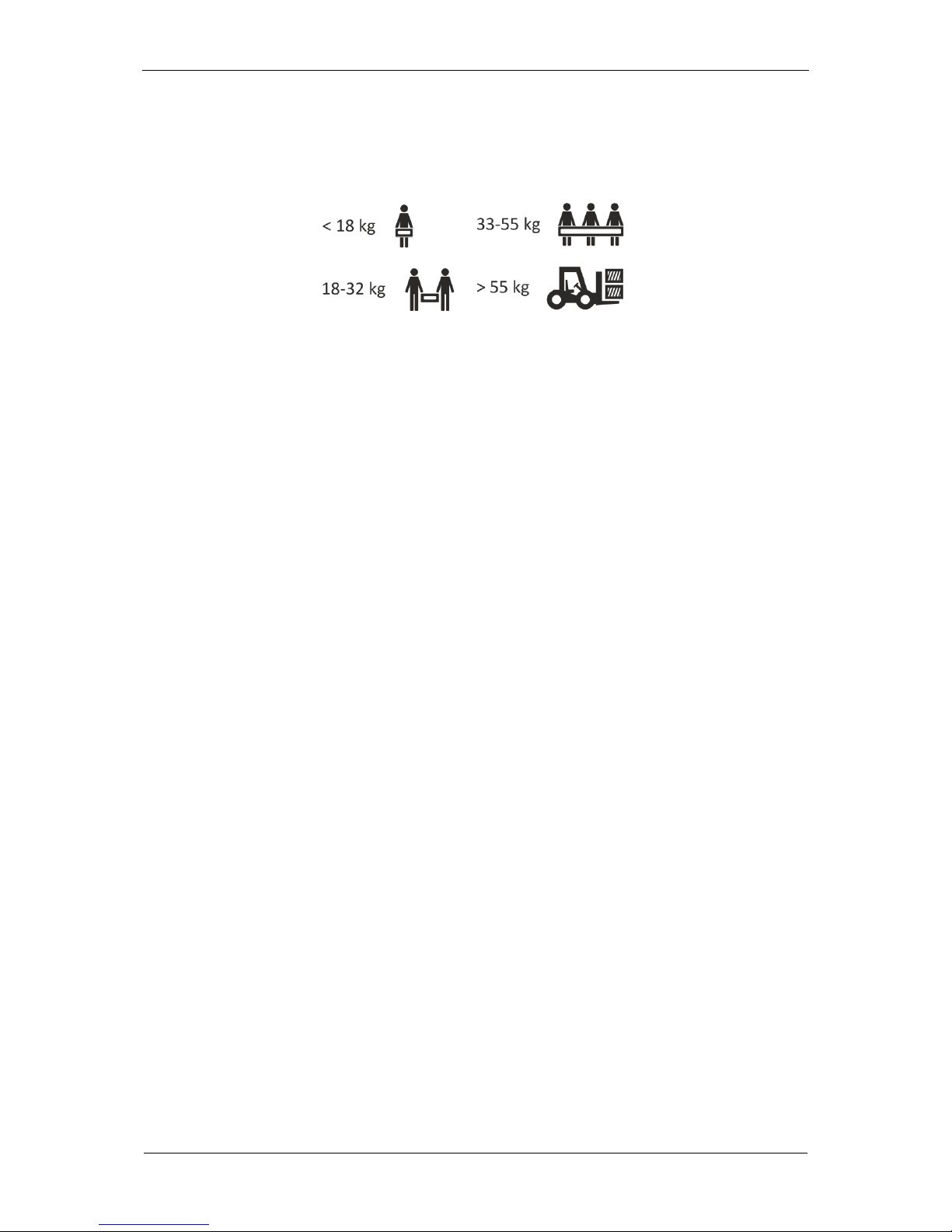
Exercise particular care when transporting the equipment, due to its heavy weight.
Heavy equipment must be moved by at least two or more persons.
UPS units may be transported only in their original packaging boxes to ensure
adequate protection against shocks, vibrations and impact.
The unit should be operated and stored in conditions meeting the requirements in
the product specification. UPS units must be stored in a dry room with suitable
ventilation.
If a UPS is to be stored over a longer period of time, its batteries must be
recharged at least every 6 months. The recharging procedure must always be
recorded and documented.
Always make sure to check the date when recharging is due. Do not use the UPS
unit if the deadline has passed and the batteries have not been recharged. In
such cases always contact service support.

EVER UPS POWERLINE RT 6000 / 10000 series instruction manual
11
www.ever.eu
Pomoc Techniczna, tel.: +48 61 6500 400
2017-01-05 13:16
UPS DESCRIPTION AND INSTALLATION
GENERAL INFORMATION
The POWERLINE RT UPS is a modern electronic equipment providing a source
(autonomic in a specific work state) of a ~230 V sine wave voltage. This unit belongs
to a series of uninterruptible ONLINE class UPS devices whose characteristic feature
is constant transformation of power. This feature allows POWERLINE RT to condition
the power of the input line. Regardless of voltage fluctuations and input signal
distortions, the POWERLINE RT UPS maintains a fixed-value sine wave output. The
user may set the following voltage values via the LCD panel: 208 / 220 / 230 /
240 V AC. The default setting is ~230 V. The UPS unit operates in the mains mode
(without drawing any energy from the batteries) in a wide range of voltages between
~120÷276 V (voltage between phases) for the 50% load power and ~176÷276 V for
the 100% load power, supplying receivers with the earlier set voltage. Another
advantage of continuous power transformation featured in ONLINE UPS units is that
no interruption is needed when switching to another source of power (mains battery). Loads connected to the UPS output do not even detect switching between
the mains and battery operation.
The POWERLINE RT UPS systems consist of the following functional blocks:
rectifier set with PFC (Power Factor Correction)
battery charger
battery set in an internal battery module
inverter
autonomous bypass system
manual (service) bypass system
microprocessor-based control system with measurement circuits.
The input rectifier transforms the alternating current voltage from the mains into direct
current voltage. The applied power factor correction (PFC) system allows to reduce
the consumption of reactive power. A DC voltage bus is the basic source of power for
the inverter system, which in turns generates a single-phase, sinusoidal AC voltage
with model parameters to be used to power the loads. The independent charger
charging the batteries has a very low variable component, translating into
EVER UPS POWERLINE RT 6000 / 10000 series instruction manual
2017-01-05 13:16
Technical Support, tel.: +48 61 6500 400
www.ever.eu
12
significantly extended battery life. The microprocessor-based control system ensures
precision and reliability of the entire power supply system.
The automated bypass system helps to increase the overall operating security of the
entire system. In case of the failure of the inverter, the power from mains is supplied
directly to the receivers. In this way the automated by-pass system works as an
additional passive protection of the load.
The manual bypass allows switching over completely to supplying power to the
connected loads from the mains only. That way, maintenance and service works can
be completed conveniently.
CAUTION! Before the device installation, it is obligatory for the user to
read safety instructions in the previous chapter.
UNPACKING THE PRODUCT
Keep the packaging for future transportation operations.
The UPS unit must be properly examined upon delivery or handover. Although the
product is solidly packaged, the appliance could have been damaged due to shocks
experienced during transport. If any of the units is damaged during transportation, a
complaint for transportation damage should be filed. Should any product damage be
discovered upon receiving the product, the carrier or the vendor must be notified
immediately (a complaint should be filed).
CAUTION! The product is supplied with the batteries connected.
CAUTION! Water vapor may condensate on the UPS unit's elements if
packaging is removed from the device in low temperatures. Do not install
the UPS until its interior and housing are completely dry (shock risk).
CAUTION! The appliance is heavy. Considerable care is required when
it is being unpacked or moved.
Exercise caution when moving or unpacking the device. Refrain from
unpacking its individual elements until they are required for installation.
EVER UPS POWERLINE RT 6000 / 10000 series instruction manual
13
www.ever.eu
Pomoc Techniczna, tel.: +48 61 6500 400
2017-01-05 13:16
Unpacking the device:
Step 1:
Open the packaging and take out parts packed together with the device (see: fig. 1 i
2).
POWERLINE RT 6000 UPS:
Fig. 1: Unpacking the POWERLINE RT 6000 UPS.
POWERLINE RT 10000 UPS:
Fig. 2: Unpacking the POWERLINE RT 10000 UPS.
EVER UPS POWERLINE RT 6000 / 10000 series instruction manual
2017-01-05 13:16
Technical Support, tel.: +48 61 6500 400
www.ever.eu
14
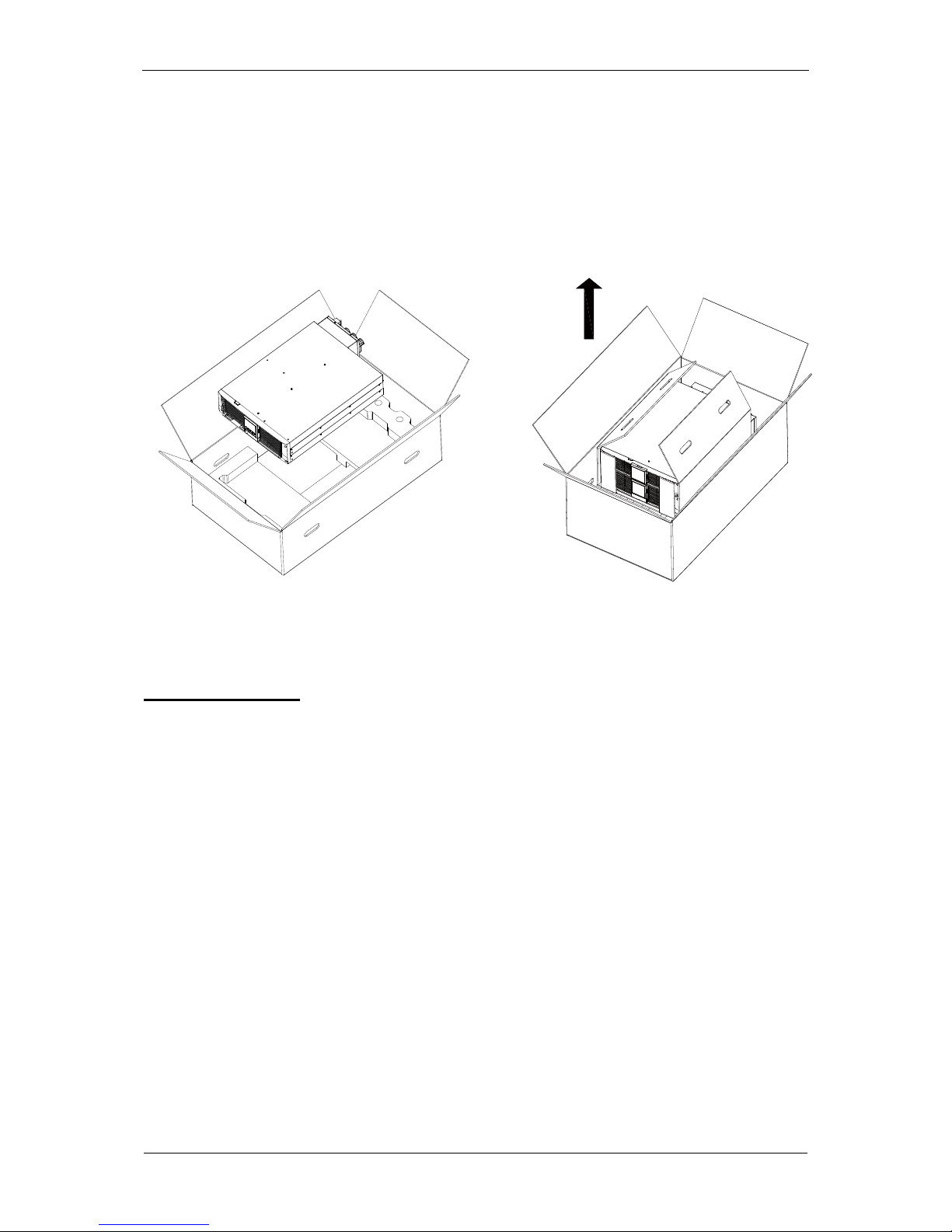
Step 2:
Two people (one at each side) carefully take the device out of the packaging and
place it on a flat, stable surface (see: fig. 3).
Place the device in a safe location, provided with proper air flow rate and free of
damp, flammable gases and corrosion hazards.
POWERLINE RT 6000
POWERLINE RT 10000
Fig. 3: Lifting the POWERLINE RT 6000 / 10000 UPS.
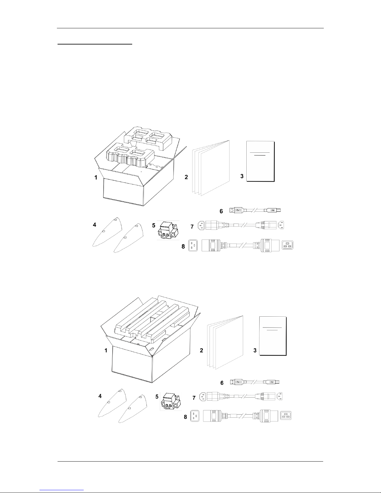
What’s in the box?
Check carefully the contents of the packaging. The packaging should contain the
following (fig. 1 and 2):
1. UPS.
2. User's manual.
3. Warranty card.
4. Tower type supports set for installing the unit vertically.
5. EPO jumper.
6. USB communication cable to connect the UPS with a computer.
7. IEC C13-C14 10 A power supply cable x 1
8. IEC C19-C20 16 A power supply cable x 1
EVER UPS POWERLINE RT 6000 / 10000 series instruction manual
15
www.ever.eu
Pomoc Techniczna, tel.: +48 61 6500 400
2017-01-05 13:16
Rack Kit for installing UPS units / battery modules in a Rack (optional).
A set of elements for installing the unit in the Rack:
1. 2 front rack supports with installation screws,
2. 2 sliding rack guides (with profiles and their screws).
For the detailed list of the Rack Kit elements with assembling instructions for the
Rack, see the assembling instructions at www.ever.eu.
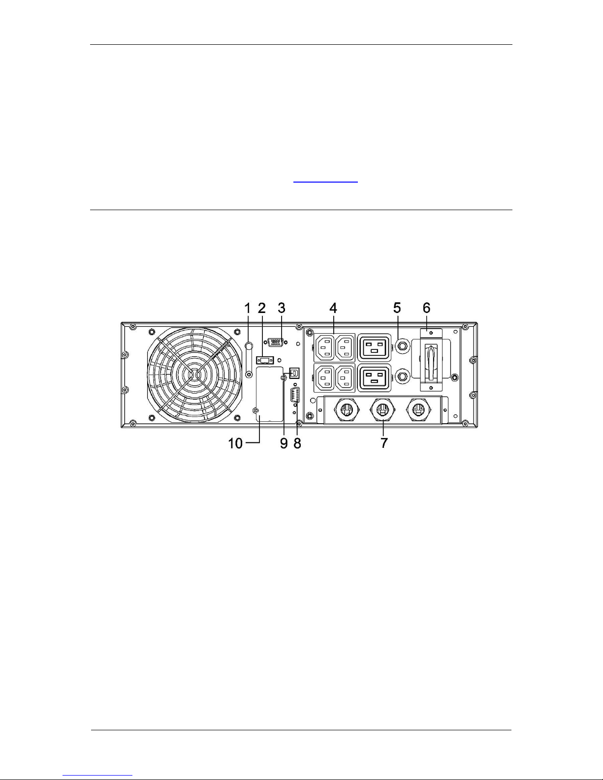
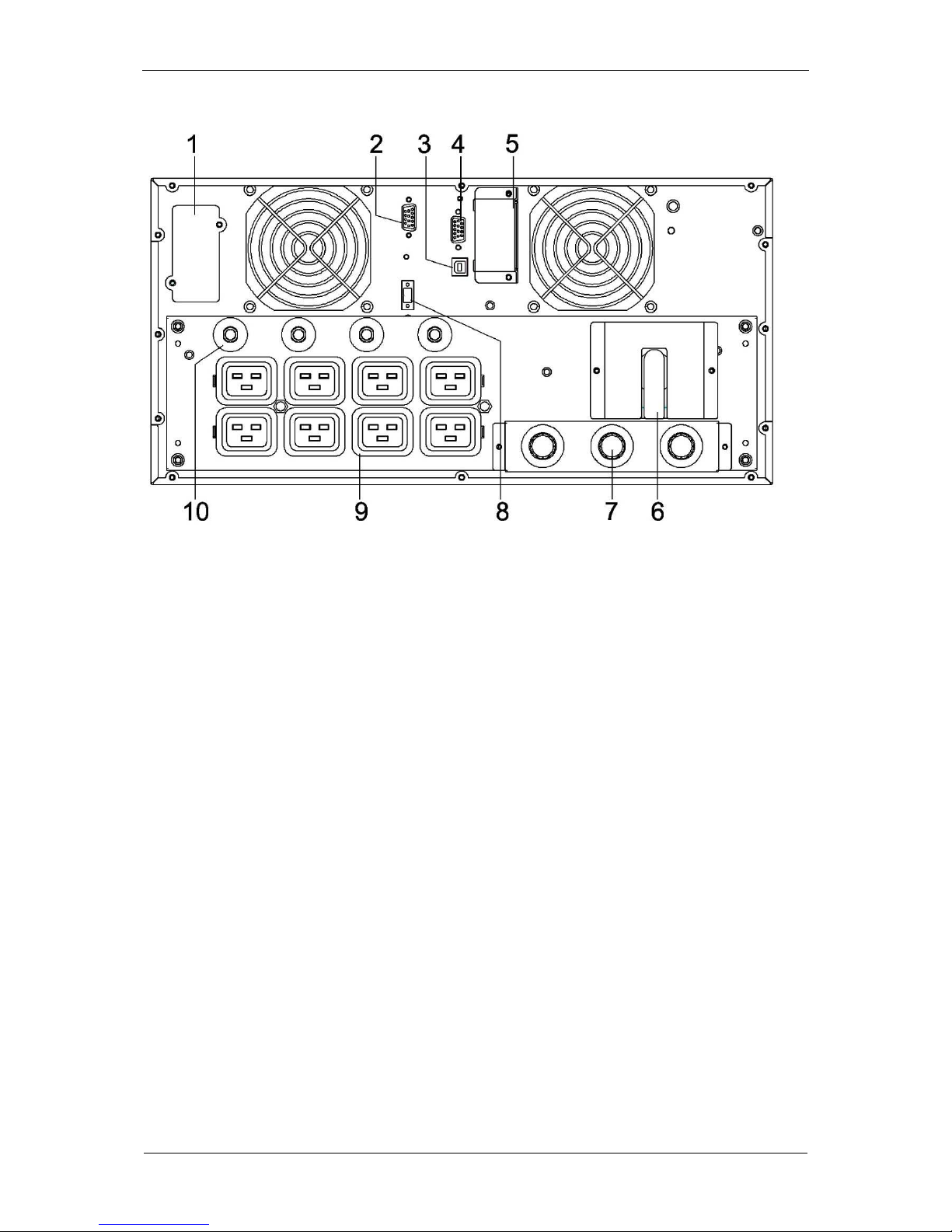
ELEMENTS OF THE UPS - REAR PANEL
Elements of the rear panel of specific POWERLINE RT models is shown in fig. 4 and
5.
6 kVA model view:
Fig. 4: View of the rear panel elements in POWERLINE RT 6000 UPS.
1. Functional earthing clamp.
2. EPO connector.
3. Communication interface for parallel operation.
4. Output sockets (10 A) x 4 + output sockets (16 A) x 2
5. Output circuit fuses.
6. Service bypass switch.
7. Power supply, output and bypass lines connection clamps.
8. RS-232 communication port.
9. USB communication port.
10. SNMP card slot.
EVER UPS POWERLINE RT 6000 / 10000 series instruction manual
2017-01-05 13:16
Technical Support, tel.: +48 61 6500 400
www.ever.eu
16
10 kVA model view:
Fig. 5: View of the rear panel elements in POWERLINE RT 10000 UPS.
1. SNMP card slot.
2. Communication interface for parallel operation.
3. USB communication port.
4. RS-232 communication port.
5. External batteries modules connector.
6. Service bypass switch.
7. Power supply, output and bypass lines connection clamps.
8. EPO connector.
9. 16 A output sockets.
10. Output circuit fuses.
EVER UPS POWERLINE RT 6000 / 10000 series instruction manual
17
www.ever.eu
Pomoc Techniczna, tel.: +48 61 6500 400
2017-01-05 13:16
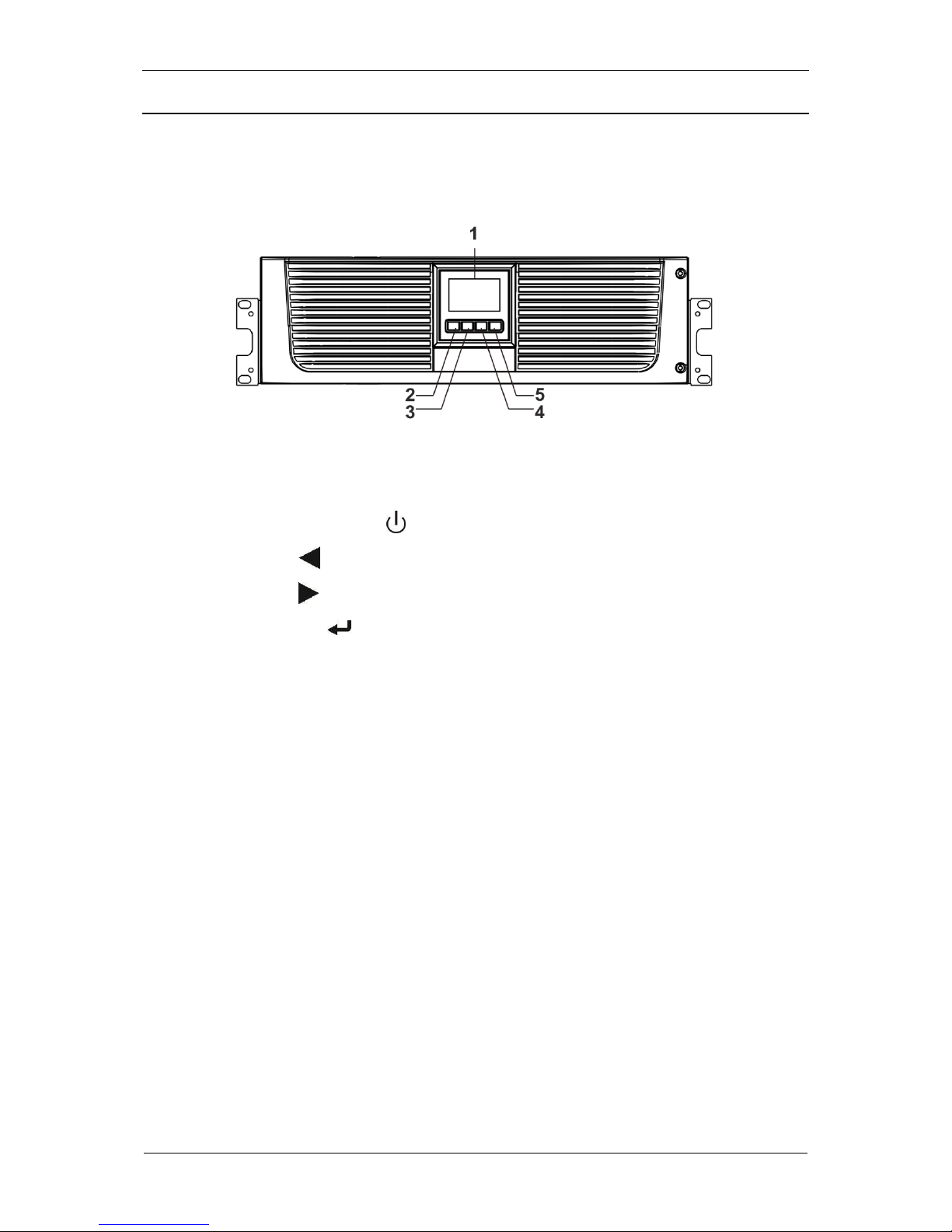
HOW IT WORKS
Fig. 6 shows POWERLINE RT front panel elements (both UPS models have identical
LCD displays and control buttons).
Fig. 6: View of the front panel elements in POWERLINE RT UPS.
1. LCD display.
2. Start / shut down button .
3. Scroll button (up / back).
4. Scroll button (down / forward).
5. Selection button .
The UPS features a 4-button control panel and an LCD display with a dual colour
backlight. In a normal situation a white text is shown on a blue background. In case
of a critical alarm text colour changes to dark amber and the background colour
changes to red.
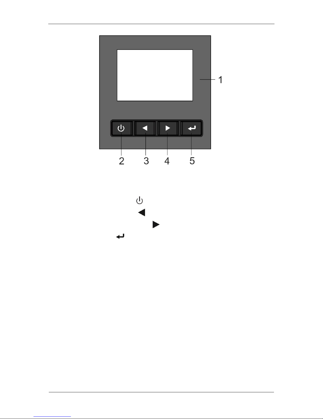
Figure 7 shows the display and the control panel, as well as the description of its
elements. Table 1 presents the description of the keys of the control panel and Table
2 presents the description of information icons of the LCD display.
EVER UPS POWERLINE RT 6000 / 10000 series instruction manual
2017-01-05 13:16
Technical Support, tel.: +48 61 6500 400
www.ever.eu
18
Fig. 7: POWERLINE RT 6000 / 10000 UPS control panel:
1. LCD display.
2. Start / shut down button .
3. Scroll button (up / back) .
4. Scroll button (down / forward) .
5. Selection button .
EVER UPS POWERLINE RT 6000 / 10000 series instruction manual
19
www.ever.eu
Pomoc Techniczna, tel.: +48 61 6500 400
2017-01-05 13:16
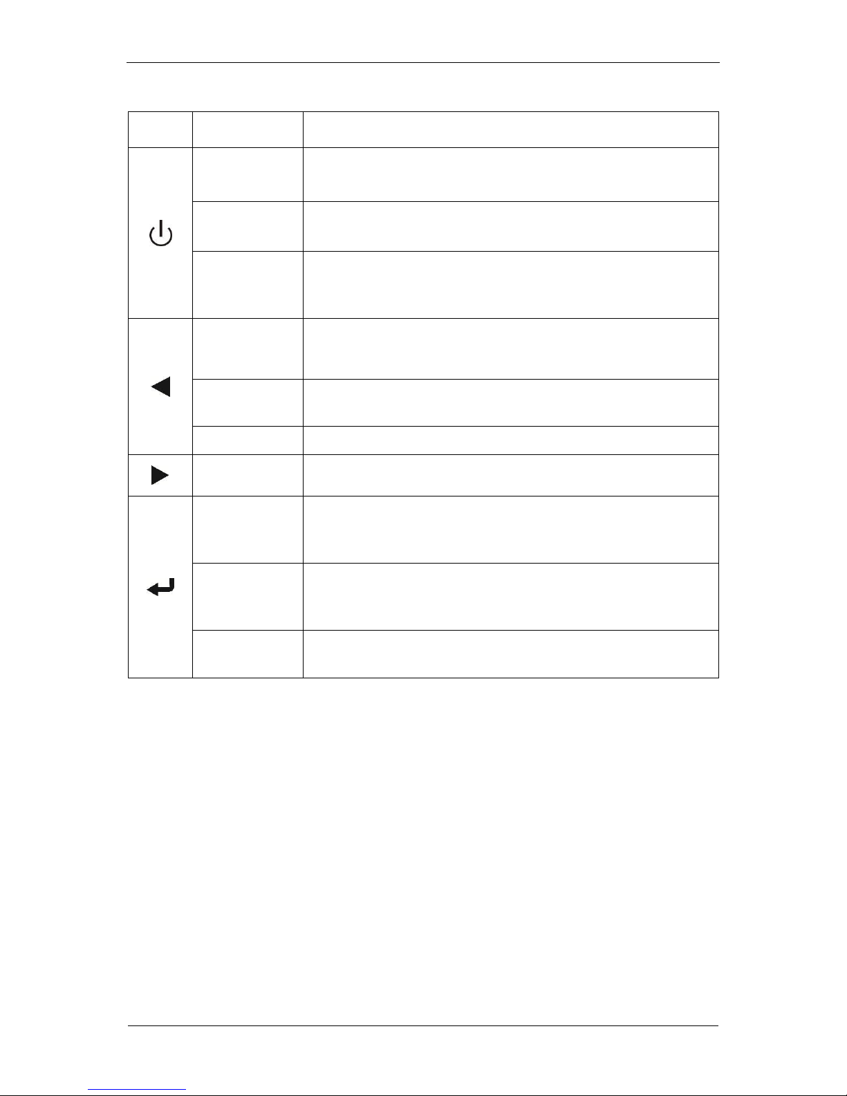
Table 1. Functions of the control panel buttons
Button
Function
Description
Turning on
When the device is powered and operates in the bypass mode, hold
this button for >1s to turn it ON.
Turning off
When the device is on, hold this button for >3 s to turn it off.
"Cold start"
Turning on in
battery mode.
When the device is not powered by the mains (when it uses the
batteries), hold this button from 0.1 s to 1 s to switch on powering
receivers at the output of the UPS unit.
Access to main
menu
When showing the UPS status default summary screen, hold this
button for >1 s to enter the main menu.
Exit from main
menu
Hold this button for >1 s to exit the current menu and enter the
system status default menu, without changing any setting.
Scrolling up
Hold this button from 0.1 s to 1 s to navigate up the menu options.
Scrolling down
Hold this button from 0.1 s to 1 s to navigate down the menu options.
Access to next
tree view
submenu
Hold this button from 0.1 s to 1 s to navigate to the next menu.
Choosing
current menu
option
Hold this button from 0.1 s to 1 s to choose the current menu option,
without changing any setting.
Confirming
current setting
Hold this button for >1 s to confirm current or currently entered
setting.
 Loading...