

Everpower Electronics EPA 1204, EPA 1210, EPA 1207, EPA 1205, EPA 1215 Instruction Manual
...
7-STAGE AUTOMATIC
BATTERY CHARGER
MCU CONTROLLED & HIGH FREQENCY SWITCHMODE
Instruction Manual
Please read user manual carefully before use.

1
◆ Explosive gases may escape from the battery during charging. Prevent
flames and sparks. Provide adequate ventilation.
◆ Before charging, read the instructions.
◆ For indoor use. Do not expose to rain.
◆ For charging 12 Volt or 24 Volt lead acid batteries ONLY.
◆ Disconnect the 110V/220-240V AC mains supply before making or breaking
the connections to the battery.
◆ The battery charger must be plugged into an earthed socket-outlet.
◆ Connection to supply mains is to be in accordance with National wiring rules.
◆ Do not attempt to charge non-rechargeable batteries.
◆ Never charge a frozen battery.
◆ If the AC cord is damaged do not attempt to use. It must be replaced or
repaired by a qualified person.
◆ Corrosive substances may escape from the battery during charging and
damage delicate surfaces. Store and charge in a suitable area.
◆ Ensure all vehicle accessories including lights, heaters, appliances etc are
turned off prior to charging.
◆ This appliance is not intended for use by young children or infirm persons
unless they have been adequately supervised by a responsible person to
ensure that they can use the appliance safely.
◆ Young children should be supervised to ensure that they do not play with the
appliance.
1. WARNING
7-STAGE AUTOMATIC CHARGING
This is a fully automatic battery charger with 7 charge stages.
Automatic charging protects your battery from being overcharged. So you can
leave the charger connected to the battery indefinitely.
7-stage charging is a very comprehensive and accurate charging process that
gives your battery longer life and better performance compared to using
traditional chargers.
7-stage chargers are suitable for most battery types including Calcium, Gel and
AGM batteries. They may also help restore drained and sulphated batteries.
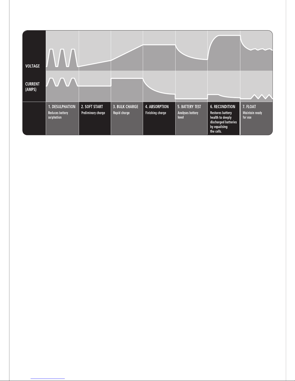
The 7 stages are:
Desulphation ; Soft Start; Bulk; Absorption; Battery Test; Recondition and Float.
2. FEATURES
2
Desulphation
The Desulphation stage may break down sulphation that occurs in batteries that
have been left flat for extended periods of time, returning them back to full charge.
sulphation occurs when lead-sulphate hardens and clogs up the battery cells.
Soft Start
A preliminary charge processes that gently introduces power to the battery. This
protects the battery and increases battery life.
Bulk (Constant Current)
Bulk mode charges the battery at the maximum rate (constant current) putting a
large amount of power into the battery in a short amount of time. This stage will
charge the battery to approximately 80%, until the voltage reaches 14.4 volts for
12V charger or 28.8 volts for 24V charger.
Bulk mode for the charging cycle. The start phase continues until the battery's
terminal voltage has risen above the set limit, at which point the charger
switches to bulk charging. If the terminal voltage has not passed the voltage
limit within the time limit, the charger switches to fault mode (lamp ③ solid) and
discontinues the charging. If so, the battery is faulty or its capacity is too large.
Absorption (Constant Voltage)
The charge rate slows down so the battery can absorb more power and reach
100% charge. The voltage remains at a constant 14.4 volts for 12V charger or
28.8 volts for 24V charge while the current is gradually reduced until no more
power can be added without over-charging the battery.

Battery Test
An automatic battery test is conducted immediately after the absorption stage.
The test monitors the voltage for 90 seconds to determine if the charge was
successful.
◆12V charger If the voltage is below 13.2 volts (fail), the charger will initiate the
Recondition stage.
◆12V charger If the voltage is above 13.2 volts (pass), the charger will proceed
to the final stage: Float.
◆24V charger If the voltage is below 26.4 volts (fail), the charger will initiate the
Recondition stage.
◆24V charger If the voltage is above 26.4 volts (pass), the charger will proceed
to the final stage: Float.
This recondition stage can recover batteries from a deeply discharged state
increasing performance and battery life.
RECOND- This mode is used to recover deep discharged flooded batteries
where you could expect a stratified acid (high acid weight in the bottom, low on
top). Check with battery manufacturer when in doubt. Use this mode with care,
because the high voltage will cause some water loss. 16V/32V is normally no
problem for electronics in 12V/24V system. Consult your supplier when in
doubt. Life of light bulbs will be reduced at higher voltage. Try to disconnect
light from the battery during this phase. Maximum effect and minimum risk for
electronics is achieved by charging a disconnected battery.
Float
The Float stage maintains the battery at 100% charge without overcharging or
damaging the battery. This means the charger can be left connected to the
battery indefinitely.
The battery charger has an 7-step fully automatic charging cycle. the cycle is
repeated infinitely. If the terminal voltage drops below a lower limit, the charger
automatically goes back to the beginning of the charging curve.
Recondition
The battery reconditioning function is initiated automatically in the case that the
battery fails the battery test (stage 5). Failing the battery test indicates that the
absorption stage was unable to fully charge the battery. The recondition mode
will then begin to introduce a low constant current for a period of 4 hours. Then
the charger will go into float charging mode.
3

4
Using the latest technology in battery chargers, switch mode chargers convert
110V/220-240V AC power to 12V/24V DC power using electronic components
unlike traditional battery chargers that rely on heavy transformers. This allows
the charger to be light weight and compact without sacrificing on performance.
3. SWITCHMODE TECHNOLOGY
POLARITY PROTECTION
Prevents the output leads from sparking due to accidental reverse connection
or short circuit, making the charger safer to use around batteries.
OUTPUT SHORT PROTECTION
Short circuit connection of the clips: Check clips are not touching each other
OR Check the clips are correctly connected to the battery.
NON BATTERY LINK PROTECTION
BIf battery charger connects with non battery load,it will go into protection state.
FAULTY BATTERY
Bulk charging has timed out and stopped after 24 hours. Battery is faulty and
may need to be replaced.
OVER VOLTAGE PROTECTION
The 12V charger will automatically protection if the voltage is higher than 17.5V.
The 24V charger will automatically protection if the voltage is higher than 35V.
OVER TEMPERATURE PROTECTION
O
Internal temperature is above 65 C +/-5 C
COOLING FAN
The charger is fitted with a thermostatically controlled fan to cool onboard
electronics and maintain charging performance. The cooling fan will engage
automatically when there is a high load on the battery or there is sufficient heat
build up.
O
4. PROTECTIVE FEATURES
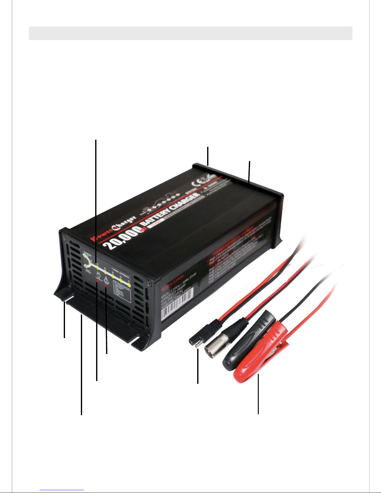
The 7-stage automatic charging consists of the following components:
LED Charge Status Display Indicates Power,
Charging and Fully Charged
Power on LED
Fault LED
Power cord
DC leads
Thermostatically contro
5
5. PRODUCT OVERVIEW
Power on LED
Fault LED
5cm
Mounting hole
Mounting flange
Switch on/off
Thermostatically conrolled cooling fan
Quick connector
DC leads

6. CHARGE STATUS INDICATOR
The CHARGING and FULLY CHARGED LEDs will illuminate and flash in various
patterns to indicate the different stages of charging. See below for flash patterns.
Note: : SOLID FLASH EXTINGUISH
POWER ON LED: Red LED illuminates (solid) when power on.
CHARGING LED: Yellow LED illuminates and flashes when 7-stage charging
process.
FULLY CHARGED LED: Green LED illuminates (solid) when fully charged.
FAULT LED: When Red LED illuminates and flashes, it may be caused by:
1. Reverse connection between positive and negative of the DC lead.
2. Battery charger output short.
3. Non battery link.
4. 12V charger connects to a battery voltage higher than 17.5V or 24V charger
connects to a battery voltage higher than 35V.
O
5. Charger's internal temperature is higher than 70 C
6. When Red LED flashes and Yellow LED illuminates (solid) means bulk
charging has timed out and stopped after 24 hours.
: :
Power Off
Power On
Charging
1. Desulphation
2. Soft Start
3. Bulk
4. Absorption
5. Battery Test
6. Recondition
7. Float
Fully Charged
Non Battery Link
Protection
Output Polarity Reverse
Protection
Output Short Protection
Over Voltage Protection
Faulty Battery
Thermal Protection
Red LED
●Power On
Yell LED
●Charging
Green LED
●Fully Charged
Red LED
●Fault
(Bulk Led)
6

7. SPECIFICATIONS
Charger type
Input Voltage
Input Power
Output Voltage
Output Current
Minimum Start Voltage
Desulphation
Soft Start
Bulk
Absorption
Battery Test
Recondition
Float
Efficiency
Thermal Protect
Ambient temperature
Over Voltage Protection
Deep Cycle
Types of Batteries
Dimension(LxWxH)
Weight
7-Stage automatic 7-Stage automatic 7-Stage automatic 7-Stage automatic
123W
12V DC
4A
2V
250VAC, T3.15A 250VAC, T3.15A 250VAC, T3.15A 250VAC, T3.15A
154W
12V DC
5A
2V
215W
12V DC
7A
2V
307W
12V DC
10A
2V
Pulse charge up to 11V
Half the rated set current up to 12V
4A (Up to 14.4V)
Constant
voltage until
current drops
to 0.6A
5A (Up to 14.4V)
Constant
voltage until
current drops
to 0.75A
7A (Up to 14.4V)
Constant
voltage until
current drops
to 1.05A
10A (Up to 14.4V)
Constant
voltage until
current drops
to 1.5A
Monitors voltage for 90 seconds
Constant
current (0.6A)
for 4 hours
limited to 16V
Constant
current (0.75A)
for 4 hours
limited to 16V
Constant
current (1.05A)
for 4 hours
limited to 16V
Constant
current (1.5A)
for 4 hours
limited to 16V
13.8V also with pulse feature
App.85%
65 +/-5
O O
C C
-20℃ to +50℃, output power is reduced automatically at high temperatures
The 12V charger will automatically if the voltage is higher than 17.5V.protection
30-80 35-100Ah
50-140Ah 70-200Ah
Most types of lead acid batteries including Calcium, GEL and AGM
195x115x62mm
1.0Kg
195x115x62mm 195x115x62mm 195x115x62mm
1.03Kg 1.05Kg 1.07Kg
BATTERY RANGE
P/No. E PA 1204 E PA 1205 E PA 1207 E PA 1210
Current Fuse Rating
Current Fuse Rating
250VAC, T3.15A 250VAC, T3.15A 250VAC, T3.15A 250VAC, T3.15A
220-240V~, 50/60Hz 110V~, 50/60Hz
Specifications are subjected to change without prior notice.
7
Cooling Fan
Automatic temperature controlled

Charger type
Input Voltage
Input Power
Output Voltage
Output Current
Minimum Start Voltage
Desulphation
Soft Start
Bulk
Absorption
Battery Test
Recondition
Float
Efficiency
Thermal Protect
Ambient temperature
Over Voltage Protection
Deep Cycle
Types of Batteries
Dimension(LxWxH)
Weight
250VAC, T3.15A 250VAC, T3.15A 250VAC, T3.15A 250VAC, T3.15A
Pulse charge up to 11V
Half the rated set current up to 12V
Constant
voltage until
current drops
to 1.8A
Constant
voltage until
current drops
to 2.25A
Constant
voltage until
current drops
to 3.0A
Monitors voltage for 90 seconds
Constant
current (1.8A)
for 4 hours
limited to 16V
Constant
current (2.25A)
for 4 hours
limited to 16V
Constant
current (3.0A)
for 4 hours
limited to 16V
13.8V also with pulse feature
App.85%
65 +/-5
O O
C C
-20℃ to +50℃, output power is reduced automatically at high temperatures
The 12V charger will automatically if the voltage is than 17.5V.protection higher
Most types of lead acid batteries including Calcium, GEL and AGM
BATTERY RANGE
P/No. E PA 1212 E PA1 215 E PA 1220
Current Fuse Rating
Current Fuse Rating
220-240V~, 50/60Hz 110V~, 50/60Hz
7-Stage automatic7-Stage automatic7-Stage automatic
332W
12V DC
12A
2V
250VAC, T3.15A
415W
12V DC
15A
2V
250VAC, T3.15A
554W
12V DC
20A
2V
250VAC, T5A
12A (Up to 14.4V) 15A (Up to 14.4V) 20A (Up to 14.4V)
80-240Ah
100-300Ah 134-400Ah
195x115x62mm 215x115x62mm 215x115x62mm
1.2Kg 1.25Kg
1.3Kg
Specifications are subjected to change without prior notice.
8
Cooling Fan
Automatic temperature controlled
8. SPECIFICATIONS

Charger type
Input Voltage
Input Power
Output Voltage
Output Current
Minimum Start Voltage
Desulphation
Soft Start
Bulk
Absorption
Battery Test
Recondition
Float
Efficiency
Thermal Protect
Ambient temperature
Over Voltage Protection
Deep Cycle
Types of Batteries
Dimension(LxWxH)
Weight
250VAC, T3.15A 250VAC, T3.15A 250VAC, T3.15A
Pulse charge up to 22V
Half the rated set current up to 24V
Constant
voltage until
current drops
to 0.75A
Constant
voltage until
current drops
to 1.5A
Monitors voltage for 90 seconds
Constant
current (0.75A)
for 4 hours
limited to 32V
Constant
current (1.5A)
for 4 hours
limited to 32V
27.6V also with pulse feature
App.85%
65 +/-5
O O
C C
-20℃ to +50℃, output power is reduced automatically at high temperatures
The 24V charger will automatically if the voltage is than 35V.protection higher
Most types of lead acid batteries including Calcium, GEL and AGM
BATTERY RANGE
P/No. E PA 2405 E PA 2410
Current Fuse Rating
Current Fuse Rating
220-240V~, 50/60Hz 110V~, 50/60Hz
7-Stage automatic7-Stage automatic
296W
24V DC
5A
4V
250VAC, T3.15A
547W
24V DC
10A
4V
250VAC, T5A
5A (Up to 28.8V) 10A (Up to 28.8V)
35-100Ah
70-200Ah
215x115x62mm 215x115x62mm
1.2Kg 1.3Kg
Specifications are subjected to change without prior notice.
9
Cooling Fan
Automatic temperature controlled
9. SPECIFICATIONS

STEP 1 CHECK THE ELECTROLYTE LEVEL
Prior to charging the battery, remove the vent caps and check the electrolyte
level (not required on sealed & maintenance free batteries). The electrolyte
should be 6mm (1/4") above the battery's plates. If low, top up with distilled
water to the correct level and refit the vent caps.
STEP 2A CONNECTION OUT OF THE VEHICLE
Connect the RED lead (battery clip) from the charger to the Positive (+)
battery post.
Connect the BLACK lead (battery clip) from the charger to the Negative (-)
battery post.
STEP 2B CONNECTION IN VEHICLE
Determine if the vehicle is Positively (+) or Negatively (-) earthed. Negatively
earthed vehicles have a cable (usually black) from the Negative battery
terminal to the vehicle's chassis.
10
Connection out of vehicle
RED
BLAC K
10. CHARGING INSTRUCTIONS

Connect the BLACK lead (battery clip) from the charger to the Negative (-)
battery terminal.
Connect the RED lead (battery clip) from the charger to the vehicle's chassis
away from the fuel line or moving parts.
11
Connection in vehicle
(negatively earthed)
BLAC K
RED
Connection in vehicle
(positively earthed)
BLAC K
RED
Connect the RED lead (battery clip) from the charger to the Positive (+) battery
terminal.
Connect the BLACK lead (battery clip) from the charger to the vehicle's chassis
away from the fuel line or moving parts
11. Negatively earthed (most vehicles)
12. Positively earthed

The chassis earthing lug should be connected to an earting point which will be
depending on where the battery charger is installed. In a vehicle, connect the
chassis ground lug to the chassis of the vehicle. In a boat, connect to the boat's
grounding systems. In a fixed location, connect to earth.
STEP 3 CONNECT TO 110V/220-240V AC MAINS POWER
page 15.
page 14
Connect the battery charger to the 110V/220-240V AC mains powered socket
and turn on the mains power.
STEP 4 CHARGING
During the charge process, the CHARGING and FULLY CHARGED LED will
flash various patterns. This is normal and indicates the various charge stages.
Refer to "How can I know what stage the battery charger is in" in the FAQ
section,
When the FULLY CHARGED LED remains on, this is known as the float stage
and the charger can be left connected to the battery without over charging.
If the POWER LED is flashing, there is fault; refer to "Fault Codes" explanation
on of this manual.
STEP 5 DISCONNECTION
Ensure the 110V/220-240V AC mains switch is turned off and the charger is
disconnected from the 110V/220-240V AC mains power.
Battery out of vehicle
Remove the BLACK lead (battery clip) from the battery.
Remove the RED lead (battery clip) from battery.
Battery in vehicle
Remove the chassis connection.
Remove the battery terminal connection.
12
OUT PUT
12V D C
INP UT
AC
7-STAGE AUTOMATIC C HARGING
P/No.: MB C 1210
INPUT: 220-240 V AC, 50/60 Hz, 307W
OUTPUT: 12V DC, 10,00 0mA
FUSE: T3. 15A, 250V AC
FAN
CHA SSIS
GND
ON
OFF
13. CHASSIS EARTHING

7-stage chargers are designed for indoor, out of weather use only. Ensure that
both charger and battery are in a well-ventilated space during charging.
The battery charger end plates include a mounting flange for easy mounting.
If permanently fixed the charger should be mounted to a suitable horizontal or
vertical panel, with at least 10cm clearance from the end plates to
provide adequate ventilation for the cooling fan.
3.5mm
mounting hole
13
14. MOUNTING INSTRUCTIONS
It is possible to hard wire the DC charging leads to the battery for permanent
installations.
You will need 2 x ring terminals, an inline fuse holder and a fuse with a rating
equal to or more than twice of the chargers output. (See below)
4A = 8 Amp fuse 12A = 25 Amp fuse
5A = 10 Amp fuse 15A = 30 Amp fuse
7A = 15 Amp fuse 20A = 40 Amp fuse
10A = 20 Amp fuse
15. PERMANENT WIRING TO BATTERY

If the charger is used in a Permanent / Hard Wired application and the vehicle
will not be used for some time, it is best to leave the charger connected to
mains power (turned 'On') so that it can maintain the battery fully charged.
Ensure any modification to the 110V/220-240V AC mains lead is carried out by
a qualified person and that connection to supply mains is in accordance with
National wiring rules.
14
Inline fuse
RED
BLACK
Ring terminal
OUTP UT
12V DC
INPU T
AC
7-STAGE AUTOMATIC CHARGING
P/No.: MBC 1210
INPUT: 220-240V AC, 50/60H z, 307W
OUTPUT: 12V DC, 10,000mA
FUSE: T3.15A, 25 0V AC
FAN
CHAS SIS
GND
ON
OFF
Connection:
1. Cut off the supplied battery clips; ensure you leave sufficient cable to reach
the battery terminals. (DO NOT extend the battery charger DC cables, as the
added voltage drop will cause incorrect charging).
2. Fit a ring terminal to the BLACK Negative (-) wire.
3. Connect the inline fuse to the RED Positive (+) wire.
4. Connect a ring terminal to the other end of the inline fuse.
5. Connect the RED lead (with inline fuse and ring terminal) to the Positive (+)
battery post.
6. Connect the BLACK lead (with ring terminal) to the Negative (-) battery post.
7. Fit the correctly rated fuse.

15
10Amp
CHARGE RATE BATTERY SIZE (24V)
5Amp
35-100
70-200
7-24
7-24
Deep Cycle (AH) Charger Time (Hours)
CHARGE RATE BATTERY SIZE (12V)
Deep Cycle (AH) Charger Time (Hours)
4Amp
5Amp
7Amp
10Amp
12Amp
15Amp
20Amp
30-80
35-100
50-140
70-200
80-250
100-300
134-400
7-24
7-24
7-24
7-24
7-24
7-24
7-24
16. ADJUSTABLE CHARGE RATES: 12 VOLT BATTERY
17. ADJUSTABLE CHARGE RATES: 24 VOLT BATTERY

There are error codes that may be displayed. These will be displayed in the
following way:
16
Error Code
Charging
LED
Fault
LED
Cause
Remedy
Fully Charged
LED
Polarity Reverse
/ Output Short
Short circuit or
reverse
connection of the
clips
Check clips are not
touching each other
OR Check the clips are
correctly connected to
the battery.
Non Battery
Link
Non battery link
Please choose the
right battery type for
connection.
Over Voltage
The 12V battery
voltage is above
17.5V.
The 24V battery
voltage is above
35V.
Over
Temperature
Internal
temperature
is above
O O
65 C +/-5 C
Turn off charger and
allow to cool.
Faulty
Battery
(Bulk
Led)
Bulk charging
has timed out
and stopped after
24 hours.
Battery is faulty and
may need to be
replaced.
Disconnect the
charger and check
the battery voltage.
This charger is
suitable for 12V or
24V Batteries only.
18. FAULT CODES

FREQUENTLY ASKED QUESTIONS
Q. How do I know if the battery is charged
A. The charger's FULLY CHARGED LED will illuminate (solid). Alternatively use
a Battery. Hydrometer A reading of 1.250 or more in each cell indicates a fully
charged battery.
Q. I have connected the charger properly but the 'CHARGING LED'
does not come on
A. In some cases batteries can be flattened to the point where they have very
little or no voltage. This can occur if a small amount of power is used for a long
time, for example a map reading light is left on for a week or more. 7-Stage
chargers are designed to charge from as little as 12V charger 2.0 Volts and 24V
charger 4.0 Volts. If the voltage is lower than 2.0 Volts and 4.0 Volts use a pair of
booster cables to connect between two batteries to provide more than 2.0 Volts
and 4.0 Volts to the battery being charged. The charger can then start to charge
the battery and the booster cables can be removed.
Q. Can I use the charger as a power supply?
A. 7-Stage chargers are designed to only supply power to the battery clips when
they are connected correctly to a battery. This is to prevent sparks during
connection to the battery or if connected incorrectly by mistake. This safety
feature prevents the charger from being used as a 'Power Supply'. No Voltage
will be present at the clips until connected to the battery.
Q. How can I know what stage the battery charger is in?
A. Below are the conditions that are displayed by the LEDs for each of the
charge stages.
Charging
Desulphation
Soft Start
Bulk Absorption Battery Test Recondition Float
Fully
Charged
1 2 3 4 5 6 7
17

CAUTION
ALWAYS PLACE THE BATTERY CHARGER IN AN
ENVIRONMENT WHICH IS:
A. WELL VENTILATED.
B. NOT EXPOSED TO DIRECT SUNLIGHT OR HEAT
SOURCE.
C. OUT OF REACH FROM CHILDREN.
D. AWAY FROM WATER / MOISTURE, OIL OR GREASE.
E. AWAY FROM ANY FLAMMABLE SUBSTANCE.
F. SECURE NO RISK OF FALLING.
 Loading...