

1
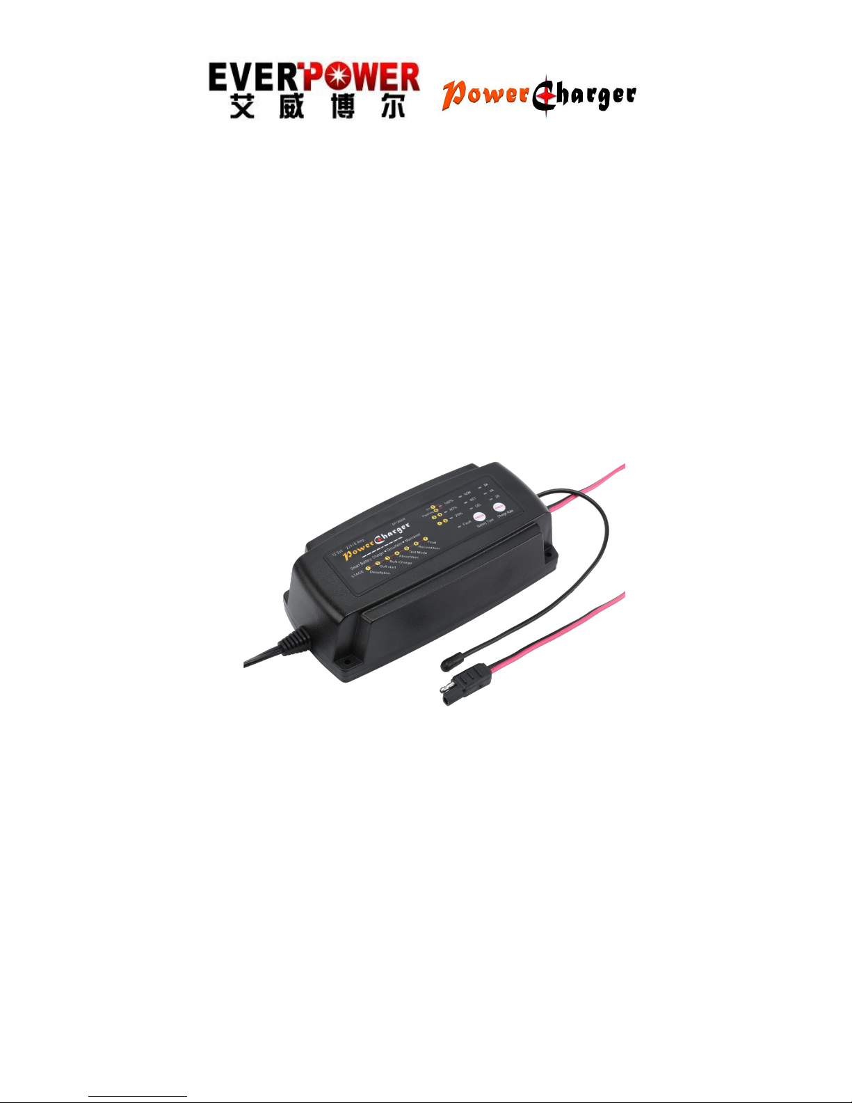
EP12M248
7 Stage
Automatic Smart Battery
Charger, Desulphuration& Maintainer
12V, 2 / 4 / 8A
FOR AGM, GEL ANDWET BATTERIES
USER MANUAL
THIS MANUAL CONTAINS IMPORTANT
SAFETY AND OPERATING INSTRUCTIONS

2
IMPORTANT SAFETY INSTRUCTIONS
Please read this manual and follow the instructions carefully
before using the charger
.
WARNING:
。The EP12M248 charger is designed to charge 12V lead-acid
batteries from 6Ah to 160Ah and maintain batteries up to 200Ah.
.
。
Checkbatte
rymanuf
acturerspec
ifi
ca
t
ion
s before us
in
g
t
hi
s cha
r
g
e
r.
。
Explosiv
egasesmayescapefro
mth
e batte
r
y
du
rin
g
cha
rging.
Provideventil
a
t
ion
t
o
p
reventflam
es and sparks
.
。
Don
ote
x
p
ose cha
r
g
e
r
t
ora
in
,
snowo
r li
q
uids
.
。
B
atte
r
y
acidis corrosive
. Rinseimmedi
ate
lywith w
ate
r i faci
d comes
in
t
o co
n
tactwit
hskinor
eyes
.
。
Don
otcha
r
g
e afrozenordamaged batte
ry.
。
Don
otcha
r
g
eno
n-rechar
g
eable batteries
.
。
Don
o
t
p
l
ace
t
h
e cha
r
g
ero
nth
e batte
rywhil
e cha
rging.
。
B
e e
xtr
a cau
t
i
oustoreduceriskofdro
pp
in
g
ameta
l
t
oolo
n
t
o
batte
ry. Itmigh
t
sparkorsho
r
t
-
circu
i
tbatt
e
r
y
oro
t
herel
ec
t
rical
p
a
r
t
t
h
a
t
m
aycause e
xplosion.
。
When workingwithal
ead-acid batte
r
y
,
remov
epersona
l m
eta
l i
t
ems
suchas
rin
g
s,bracelets
,
neckl
aces
,
w
atc
h…
。
Don
otsmoke orallowa sparko
r flamewhil
e cha
rging.
。
Inorder
t
oreduceriskofelec
t
ri
c shoc
k
,
u
npl
ugcha
r
g
e
r from A
C
ou
t
l
etbefore do
in
g
a
nymain
t
enance orclea
ning.
。
N
o
t
for
use byc
hildrenor
bya
n
y
onewhois unabletofollo
w
in
s
t
r
uc
t
ion
s o
fthismanual
,
unless
t
h
eyare supe
rv i
sed byanadu
l
t
t
o ensure
t
h
e
p
r
operuse ofcha
r
g
e
r.
MAIN FEATURES:
。
Highefficien
c
y (
>
85
%
)
.
。
Selectable cha
rgingr
atesto su
i
tbatt
e
r
y
capac
i
t
y
.
。
Selectable batte
r
yty
p
e
.
。
Tem
p
erature se
lf
-
co
m
p
ensa
t
ion:Chargingvol
t
age ada
p
tst
o
t
e
m
p
eratureto
p
reven
t
overorunderbatte
r
y
cha
rging.
。
Capable o
f rechargin
g
severe
l
y
discha
r
g
ed o
r heavil
y
sulfated
batte
ry.
。
Rever
sepola
ri
t
y
p
r
otec
t
ion
,
sho
r
t
circu
i
t
p
r
otec
t
ion
,
sparksfree
co
n
tact
.
。
U
ltralow in
p
u
t
p
owerconsu
m
p
t
ion whilein
standb
y
m
ode
.
。
E
ase ofuse.Clearcha
rgin
g
status dis
p
l
a
y
.
。
Full micr
o
p
r
ocessorco
ntrolled.
。
D
oesnotovercha
r
gey
ourbatte
r
y
eve
n if itisk
e
p
t
connected
in
main
t
enancefloa
t
m
ode
.
.naicinh
cetde
ifil
au
q
aybdec
ivr
esebtsu
mr
e
g
rah
ce
h
t
,
egamad
laci
s
y
h
p
f
os
ngi
s
y
n
aeraere
htfir
o,degamadsidrocrewo
p
e
htfI
.gninaelcelihw
rew
o
p
e
h
t
morf
t
ce
nn
ocs
iD.yllanoi
saccodenaelcebdluohsesace
hT
:E
C
NANETNIAM

3
。 Multi Charge Stages:
o Battery desulphation charging
o Soft start charging
o Bulk charging
o Absorption charging
o Battery analysis
o Recondition charging
o Float & maintenance charging
Temperature sensor
Temperature & SafetyProtection:
。 INTERNAL OVERHEAT PROTECTION: The charger is equipped
with built-in overheat and overload electronic circuit protection
。 TIMER PROTECTION: Charger provides the maximum charging
time for each charging stage. In the event it is wired to recharge a
larger than recommended battery, charger will stop charging after
maximum stage recommended time and the RED LED will be FLASH
slowly. At this point, Battery must be disconnected.
。REVERSE POLARITY: Charger has reverse battery protection. (Red
LED ON, while output leads are connected backwards), Disconnect
and correct connection to battery.
。
SHORTCIRCU
IT PROTECTION:Char
g
e
r will
t
urnoffupo
n
detec
t
in
g
a sho
r
t
circu
i
t
(
RedLEDON.
RECOMMENDEDSETTIN
G
S
:
Cha
r
g
eRate
:
Cha
r
g
e Curre
n
t
2A 4A
8
A
B
atte
r
y
Capac
i
t
y
:
Cha
rgin
g
(AH)
6
--
4
0
1
0--80
4
0
--
1
60
00
2
--
0
4
00
1
--
0
1
06--6
)
HA
(
g
nini
a
t
niaM
:
y
t
i
capaC
y
r
etta
B

4
B
atte
r
yty
p
e
:
B
atte
r
yty
p
e
A
bso
r
p
t
ion
Vol
t
age
Fl
oa
t
Vol
t
age
MAX
G
EL
ForChargin
g
GELbatteries
14.1V 13.4V
14.4V
WET
ForChargingFLOODEDor
WET B
atteries
14.4 V 13.5V
14.7V
AGM
ForChargingAGM
,
Sealed
,
VRLA
,
Calciumbatteries
14.7V 13.6V
15V
TECHNICALSPECIFICATIONS:
M
ode
l
EP12M24
8
T
y
p
e
Sma
r
t
&
A
utoma
t
i
c
In
p
u
t
(
ULVersio
n
)
115V
ac
50/60
Hz
In
p
u
t
(
C
E
12V
2/4
/ 8
A
<
0.5
V
>
2.0V
In
p
u
t
Power
W/L
oad
3
4-126W
In
p
u
t
Power
NoL
oad
0
.
3
-
0.8
W
Co
m
p
ensated
(
L*W*H
)
8
*
3
.
5
*
2
(in)
1.87LB
Approval
F
CC&C
E
)
noisreV

5
ELECTRICAL PARTS:
。 AC power cord: 6 feet SPT-2 with UL plug
。 Output lead: 6 feet SPT-1 2X18AWG with insulated battery clamps.
ENVIRONMENTAL CHARACTERISTICS:
。 Operating temperature range: 32 to 104° F
。 Storage temperature range: 10 to 170°F
。 Operating humidity range: 90% RH Max
ECO MODE:
If AC power is connected, and the battery is not connected, the charger
will automatically go into ECO mode. Input power draw in ECO mode is
less than 1.5W (0.04kWh per day).
Power consumption in maintenance mode is 0.05kWh per day.
CHARGING INSTRUCTIONS:
STEP 1 - Pre Charge:
Battery & Electrolyte Level Check
。 Check the battery electrolyte level (Only for Flooded or WET
battery).
If necessary, remove the vent caps and add distilled water so the
levels are halfway between the upper and lower fill lines.
。
STEP 2 - Connect Charger to Battery
。 If the battery is out of the vehicle:
。 Connect the Red lead from the charger to the positive (+) battery
terminal.
。 Connect the Black lead from the charger to the negative (-) battery
terminal.
。 If battery is still in the vehicle, determine if the vehicle is positively
or negatively earthed.
。 If Negatively earthed (Most Common) – First connect the Red (+)
battery charger lead to the Positive (+) battery post and then connect
the Black (-) battery charger lead to the vehicle’s chassis and away
from the fuel line.
。 If Positively earthed – First connect the Black (-) battery charger
lead to the Negative (-) battery post and then connect the Red (+)
battery charger lead to the Vehicle’s chassis and far away from the fuel
line.
STEP 3 – Connect Charger to Power (115Vac / 230Vac)
。 Connect the battery charger to AC mains powered socket.
。 The Charger will automatically start when AC power is connected
and switched on.
(Note: If the Fault Indicator LED illuminates Red, please check your
connections as it’s likely that the Positive and Negative leads are
reversed. Refer to Trouble Shooting page for further information)

6
STEP 4 – Disconnect Charger from Battery
。 If the battery is out of the vehicle:
。Switch OFF and remove the AC power socket from the outlet.
。Remove the black lead and then the red lead.
。Check electrolyte levels if possible.
(As they may need topping up with distilled water after charging)
。If the battery is in the vehicle:
。Switch OFF and remove the AC power socket from the outlet.
。Remove the lead from the vehicle chassis.
。Remove the lead from the battery.
。Check electrolyte levels if possible.
(As they may need topping up with distilled water after charging)
THE CHARGING PROCESS:
The charging stages and performance are as follows:
Battery initial condition check
After all connections are made, the charger will automatically diagnose
battery condition.
If battery voltage is above 9V, charger will go into soft start stage.
Otherwise, charger will go into desulphation mode. If the battery voltage
does not exceed 9V after 6 hours of rejuvenation, you will need to
disconnect the battery and check its condition, voltage rating or if it is
connected to a load while charging.
Smart Charging Stages
。
Desulphation:
。20% charging LED: ON.
。Engage high peak pulse for deep-discharge or sulphated battery
。dissolve the lead sulphated crystal bring the electrolyte fluid to
well-distributed state
。The battery voltage will increase slowly.
。
Soft start:
。20% charging LED: ON.
。The battery voltage will increase slowly.
。
Bulk :
。80% charging LED: ON.
。The battery can be charged about 80%.
。The charger delivers an almost constant current 2000mA until the
battery voltage reaches the set value.
。
Absorption :
。80% charging LED: ON.
。The battery can charge up to almost 95%.
。The charging current tapers and the charging voltage are kept
constant at the set value.
。
Test Mode
。The charging is interrupted for a short period while battery voltage
is measured.
。If the battery voltage falls too quickly, the battery could be faulty.

7
。FULL LED: Flashing.
。 Recondition charging
。Charger will go into this stage if battery fails Test Mode due to its
condition, age or being under charged.
。This stage can recover batteries from deeply discharged state
increasing performance and battery life.
。FULL LED: Flashing.
。
Float mode
。Full LED: ON.
。The float mode allows the charger to effectively be left connected
to your batteries; it works at a safe level and ready for use.
。
Maintenance mode
。Full LED: ON.
。The program engages a special charging waveform and monitors
the battery voltage variety, if the battery voltage sinks, the special
pulses will keep the battery in optimal state, if the battery voltage
drops even lower, the battery charger will switch into bulk charging .
The maintenance mode allows the charger to be connected to the
battery over the course of a season; If possible, check the
electrolyte liquid level in the battery.
LED status indication table:

8
TROUBLESHOOTING
:
LED Status Description
GEL Green GEL BatteryCharging
WET Green
Flooded, WET battery Charging
AGM Green
Sealed, AGM, VRLA & Calcium Battery
Charging.
20%
Green 20% capacitycharging.
80%
Green 80% capacitycharging.
100%
Flash TestModeorreconditioncharging.
100%
ON Fully charged, maintainingthe battery.
Fault ON Output short –circuit or reversepolarity.
Fault Flash Battery is Defective or capacityis too large
100%
ON
2 LEDsare lightingtogether. Battery is overvoltage.
Fault Flash
Problem Error
Code
Possible
Causes
Suggested Solution
Charger
Does Not
Work?
No
Indicator
lights on
-No AC
Power
- Check AC connections
and make sure Power
Point is switched ON
No DC
Output?
Fault
RED LED
is ON.
-Output is
short
circuited
-Reverse
polarity
connection
to Battery
- Check DC connection
between charger and
battery and make sure
they are not short
circuiting.
- Check that the crocodile
clips / ring terminals are
connected to the correct
polarity.
No
Charging
Current?
Fault
RED LED
is
flashing
-Battery is
severely
sulphated
-Overheat
protection
mode
- Move battery & Charger
to cooler environment
No
Charging
Current?
FULL &
Fault
RED LED
are
flashing
-Battery
voltage is
higher
than
charger
rate
voltage
- Check the battery
condition.
Battery may need
replacement.
Long
Charging
Time,
Full LED
Does Not
Turn On?
Fault
RED LED
is
Flashing
-Battery
capacity
too large
-Battery is
defective
- Check the charger
specification to match the
battery capacity.
- Battery cannot be
charged and must be
replaced.
 Loading...