

Page 1
USER INSTRUCTION
REFRIGERATED CABINET
xPRO
VERS. 0517
Page 2

Page 3

ENGLISH
Content
8 USER INSTRUCTIONS
Ver. 0517
8.1 CONTROLS
8.1.1 DESCRIPTION OF CONTROLS AND TOUCH-BUTTONS OF THE xPRO CONTROL PANEL ................................................
8.1.2 THE DISPLAY AND THE FUNCTIONING INDICATIONS ..........................................................................................................
8.1.3 AUTOMATIC/MANUAL TOUCH-BUTTONS SAFETY LOCKING PROTECTION AND UNLOCKING CODE .............................
8.2 OPERATION OF THE xPRO CONTROL PANEL
8.2.1 START-UP...................................................................................................................................................................................
8.2.2 SEQUENCE AND ON/OFF CODE .............................................................................................................................................
8.2.3 STOPPING THE UNIT ................................................................................................................................................................
8.2.4 DATE AND TIME SETTING ........................................................................................................................................................
8.2.5 GENERAL INFORMATION OF THE xPRO CONTROL PANEL FUNCTIONING .......................................................................
8.3 THE MAIN MENU
8.3.1 SETPOINT MENU ......................................................................................................................................................................
8.3.2 DATAS MENU ............................................................................................................................................................................
8.3.2.1 Temperature chart ...................................................................................................................................................................
8.3.2.2 Battery level ............................................................................................................................................................................
8.3.2.3 Functioning timers ...................................................................................................................................................................
8.3.2.4 Door openings .........................................................................................................................................................................
8.3.2.5 Defrosting ................................................................................................................................................................................
8.3.2.6 Sensors ....................................................................................................................................................................................
8.3.3 MANUAL DEFROST ..................................................................................................................................................................
8.3.4 ALARMS MEMORY ....................................................................................................................................................................
8.3.5 GENERAL TEST AND TEST FOR TEMPERATURES ALARM ..................................................................................................
8.3.6 SETTING MENU ........................................................................................................................................................................
8.3.6.1 Language setting ....................................................................................................................................................................
8.3.6.2 Alarm setting ...........................................................................................................................................................................
8.3.6.3 Ventilation setting ....................................................................................................................................................................
8.3.6.4 Download USB data ...............................................................................................................................................................
8.3.6.5 Reactivation alarm after muting ..............................................................................................................................................
8.3.6.6 Temperature alarm activation delay ........................................................................................................................................
8.3.6.7 Door ajar alarm activation delay .............................................................................................................................................
8.3.6.8 Codes setting ..........................................................................................................................................................................
8.3.6.9 Calibration ...............................................................................................................................................................................
5
5
5
6
6
6
6
6
6
7
7
7
8
8
8
8
8
9
9
9
9
9
10
10
11
12
12
12
12
13
13
13
8.4 OPERATION OF THE TEMPERATURE CHART RECORDER
8.4.1 DESCRIPTION OF THE TEMPERATURE CHART RECORDER ..............................................................................................
8.4.1.1 Paper chart replacement ..........................................................................................................................................................
8.4.1.2 Ink-tip replacement ...................................................................................................................................................................
8.4.1.3 Battery replacement ................................................................................................................................................................
8.5 OPERATION OF THE DIGITAL PRINTER
8.5.1 DESCRIPTION OF THE DIGITAL PRINTER ............................................................................................................................
3
14
14
14
14
14
15
15
Page 4

Page 5
Ver. 0517
8 USER INSTRUCTIONS
The information in this section of the manual regards the user or other non-specialized personnel (see par. 1.3 in the “Instruction
and Maintenance Manual”).
After the appliance has been installed in accordance with the instructions of section 3 of the “Instruction and Maintenance Manual”,
it is ready for use.
8.1 CONTROLS
According to the models, the appliance is equipped of different types of controls:
- xPRO control panel (Fig.10)
- Temperature chart recorder (Fig.22)
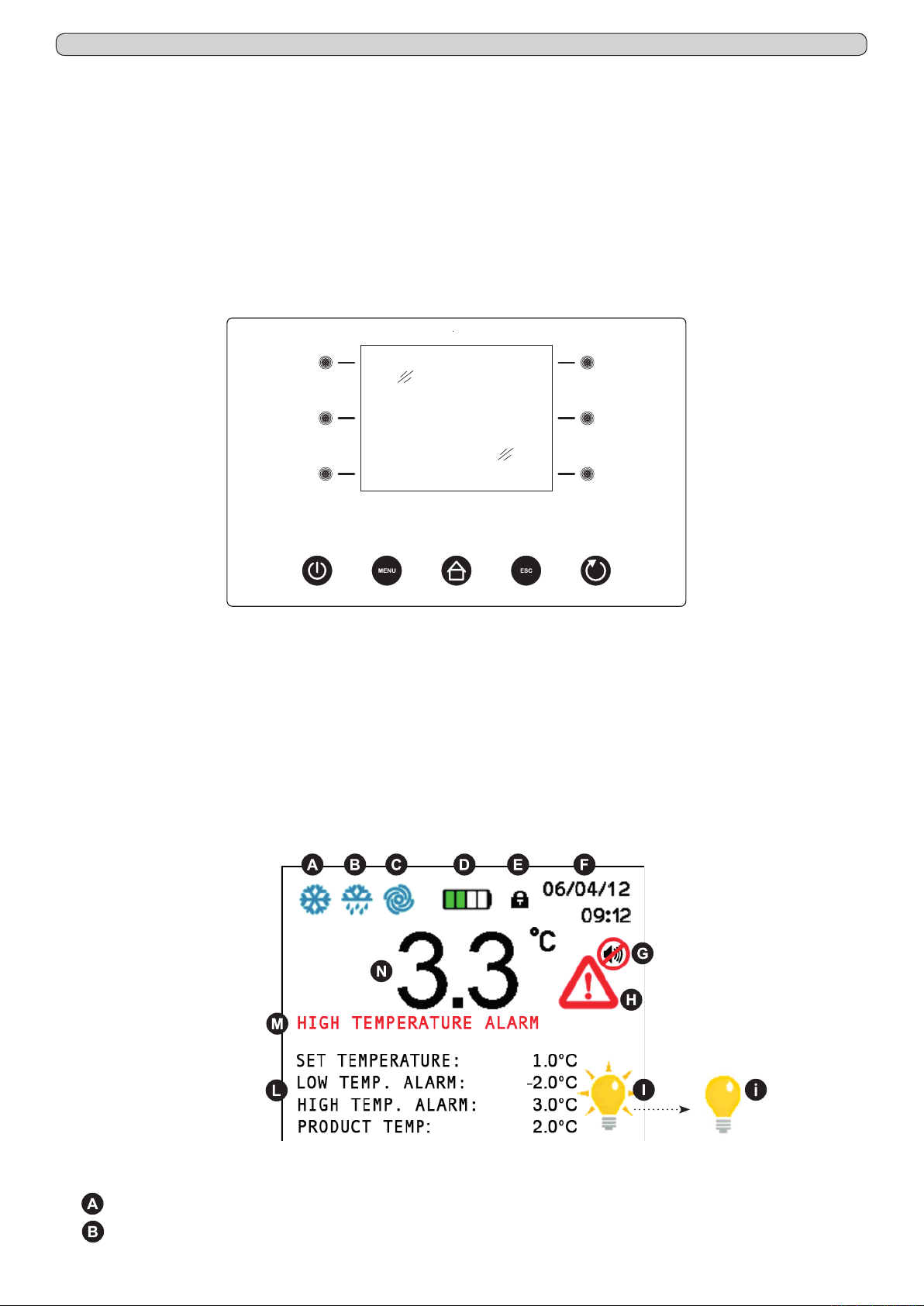
8.1.1 Description of controls and touch-buttons of the xPRO control panel (Fig.10)
(2)
(3)
(4) (7)
(8) (9) (10) (11) (12)
(1)
(5)
(6)
Fig.10
The appliance is equipped with the following controls:
- Display (1). Showing and controlling the temperature and the various machine functioning states
- Capacitive touch-buttons (2), (3), (4), (5), (6), (7). Allow various functions according to the OSD (on screen display) menu
shown on the display
- ON/OFF touch-button (8). Allows the display/appliance switching ON and OFF
- MENU touch-button (9). Allows to enter into the main menu
- HOME touch-button (10). Allows (if back-lightened) to return back to the home (main) screen-shot
- ESC touch-button (11). Allows to return back to the previous menu
- ENTER touch-button (12). Allows to enter/conrm the variations made on the function/menu shown on the display
8.1.2 The display (1) and the functioning indications (Fig.11)
Fig.11
The display shows the below listed icons/indications that, if enlightened, give indications/alert of the running functions:
COMPRESSOR: lights steadily when the compressor is running, blinks in case of starting delay or when protection is active
-
-
DEFROST: lights steadily during defrosting cycle
5
Page 6

Ver. 0517
- FAN: lights steadily when the evaporator fan is working
-
BATTERY: shows the actual charging status of the back-up battery or if a e-charging is in progress
-
TOUCH-BUTTONS LOCKING: appears and lights steadily when the touch-buttons are in protection locking mode
-
DATE/TIME: shows the actual date and time
-
BUZZER: lights steadily when acoustic alarm indication has been muted through the touch-button (6)
-
ALARM ALERT: lights steadily when an alarm is in progress. This icon is always accompanied from the relative alarm de-
scription
- INTERNAL LIGHTING: lights steadily when the internal lighting is activated. Pressing the touch-button (7), it is possible
to switch manually the internal lighting ON or OFF. When the internal lighting is not activated, it appears the icon
lighting switch also ON automatically at every door opening and switch OFF at the closing.
-
SETTINGS: show the actual appliance settings, set temperature, high and low alarm limits and if present (optionally avail-
able) the actual temperature of the stored product (simulation)
-
ACTUAL TEMPERATURE: shows the actual internal temperature of the appliance. In case the temperature is out of the
allowed limits, the indication of the temperature value pass to red colour
8.1.3 Automatic/manual touch-buttons safety locking protection and unlocking code
The xPRO control panel touch-buttons are provided with a safety locking protection to avoid tampering from unauthorized personnel.
The key locking protection has an automatic activation after 5 minutes from the last operation executed with the touch-buttons. The
key locking condition is signalled on the display, top part, with the icon of the lock-pad (
press any touch-button and enter the unlocking code 0010. To activate manually the touch-buttons safety locking protection, press
the ESC touch-button (11) and the HOME touch-button (10) even if not enlightened.
). To re-enable the use of the touch-buttons,
. The internal
8.2 OPERATION OF THE xPRO CONTROL PANEL
8.2.1 Start-up
Before starting up the unit check that the electrical connections have been made correctly as indicated in headings 3.3 and 3.4 ”Instruction and Maintenance Manual”.
Perform preliminary cleaning of the unit as described in sub-heading 5.2.1 “Instruction and Maintenance Manual”.
At the starting, when the xPRO control panel is powered, it will appear a screen-shot with the EVERmed logo for approx. 10 seconds.
Immediately after, the display will show the STAND-BY condition with the date and time with white indications on a black back-ground.
8.2.2 Sequence and ON/OFF code (Fig.10)
- if the appliance is switched OFF, but connected to the electrical network, the display shows the STAND-BY condition with the
date and time with write indications on a black back-ground
- press the ON/OFF touch-button (8) to switch the appliance ON; the display shows the screen-shot to insert the ON/OFF code
- enter the ON/OFF code 0050 through the touch-buttons (3) (6) and (4) (7)
- the touch-buttons (3)ç and (6)è have to be used to select the position where to enter the numerical value indicated from the
cursor that can be moved right and left
- the touch-buttons (4)- and (7)+ have to be used to lower and/or increase the highlighted numerical value
- having inserted the correct code, press the ENTER touch-button (12) to conrm, the appliance switch-on and the access to all
touch-buttons is enabled
At every appliance starting, it will appear the indication “Battery level low” which has to be reset pressing the enlightened touch-button (6). The battery low level alarm that appear at the starting will not be memorized in the alarms memory as it is not a real alarm,
but it is only the indication of the battery-charger starting.
8.2.3 Stopping the unit (Fig.10)
- deactivate the eventual keyboard touch-buttons locking protection (see par. 8.1.3)
- with control panel on, press the ON/OFF touch-button (8) to switch the appliance OFF
- the display shows the screen-shot to insert the ON/OFF code
- enter the ON/OFF code 0050 through the touch-buttons (3) (6) and (4) (7)
- the touch-buttons (3)ç and (6)è have to be used to select the position where to enter the numerical value indicated from the
cursor that can be moved right and left
- the touch-buttons (4)- and (7)+ have to be used to lower and/or increase the highlighted numerical value
- having inserted the correct code, press the ENTER touch-button (12) to conrm, the appliance switch-off
For further information about codes, see the menu CODE SETTING (par. 8.3.6.8).
8.2.4 Date and time setting (Fig.10)
To set the calendar and clock proceed as follow:
- deactivate the eventual touch-buttons locking protection (see par. 8.1.3)
6
Page 7
Ver. 0517
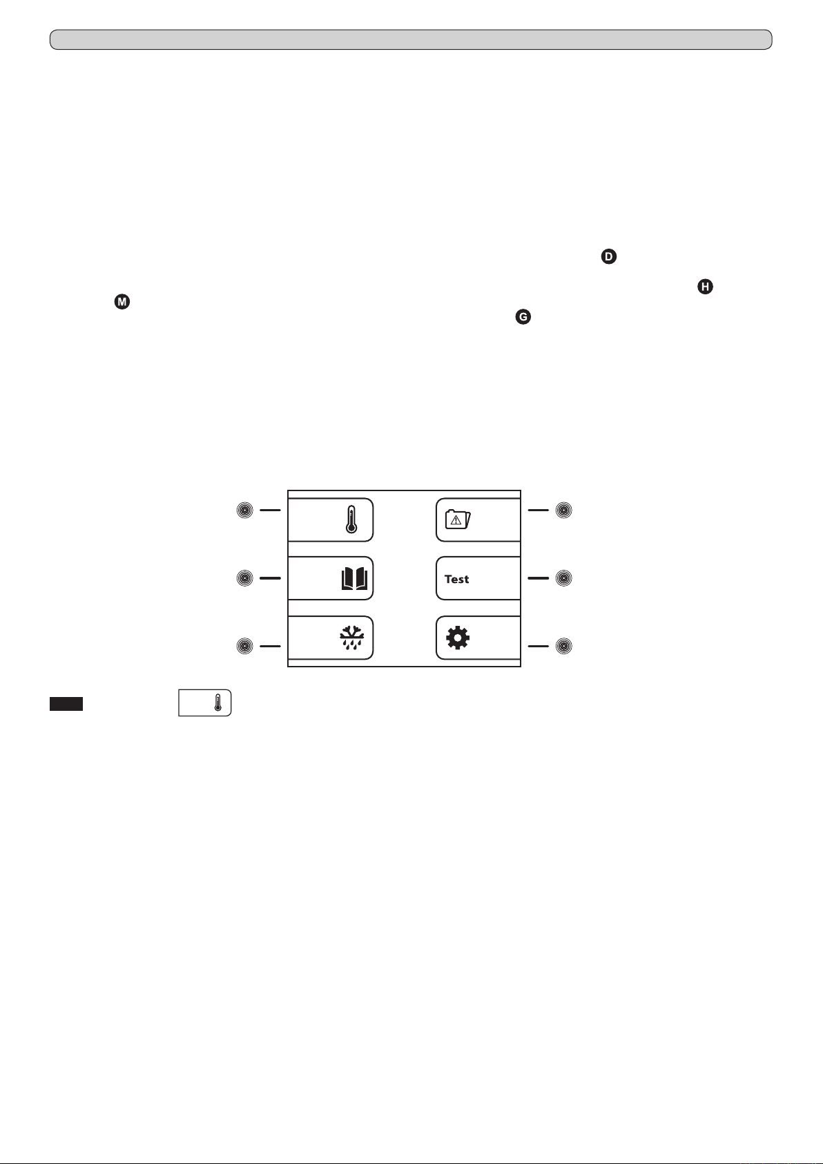
- press the MENU touch-button (9) to access to the main menu (Fig.12)
- press the touch-button (7) to access to the setting menu (Fig.15)
- press the touch-button (2) to select the menu “Date and time”
- using the touch-buttons (3)ç and (6)è highlight the position in the calendar or in the clock that should be modied
- using the touch-buttons (4)- and (7)+ to set the desired value
- repeat the last 2 operations for all the numerical values in both calendar and clock, then press the ENTER touch-button (12)
to conrm the new settings
8.2.5 General information of the xPRO control panel functioning
The xPRO control panel surveys and has the control of all the appliance functioning parameters and devices. The PRO control panel
is provided with a back-up battery that grants its operations even in case of power failure, for about 48 (depending from the charge
status). The battery charge status is automatically controlled through a special battery charging module in order to grant constantly
the maximum battery efciency. In the top part of the main screen-shot, it is always present an icon indicating the battery status
(showing charging in progress or the actual status of charge through the number of green colour charging steps).
The xPRO control panel alerts in case of abnormal functioning status with a both a visual indication (red colour icon and alarm
description ) and an acoustic signalling through a buzzer.
The acoustic alarm has muting facilities, pressing the touch-button (6) (with icon on display) and it is provided of automatic
re-activation facilities once passed the pre-set time programmable through the specic menu “Reactivation alarm after muting” in
case the alarm condition persists.
For further information about the alarms and their functioning check the paragraphs describing every single signalled alarm condition. Par. 8.3.4 and Par. 8.3.5.
8.3 THE MAIN MENU
To access to the Main Menu (Fig.12) press the MENU touch-button (9) (Fig.10). (enter the touch-buttons unlocking protection code
0010 if needed)
(2)
(3)
(5)
(6)
(4) (7)
Fig.12
8.3.1 Setpoint Menu
The appliance is factory set for operation at the following temperature:
- serie MPR xPRO: +2°C / +15°C
- serie LR xPRO: 0°C / +15°C
- serie BBR xPRO: +4C
- serie LFG xPRO: -5°C / -20°C
- serie LF xPRO: -5°C / -20°C ~ -25°C
- serie LDF xPRO: -15°C / -30°C
- serie PDF xPRO: -25°C / -40°C
- serie LCRR xPRO: 0°C / +15°C (refrigerator compartment), 0°C / +15° (refrigerator compartment)
- serie MPRR xPRO: 2°C / +15°C (refrigerator compartment), 2°C / +15°C (refrigerator compartment)
- serie LCRF xPRO: 0°C / +15°C (refrigerator compartment), -5°C / -20°C ~ -25°C (freezer compartment)
(touch-button (2) Fig.12)
To set the desired working temperature, proceed as follow:
- from the main menu screen-shot, press the touch-button (2) to access to the SETPOINT menu
- using the touch-buttons (4)- and (7)+ to set the desired value
- press the ENTER touch-button (12) to conrm the new setting and the ESC touch-button (11) to return back to the previous
menu
Press the MENU touch-button to return back to the main menu screen-shot without making any modication to the Setpoint value.
If no touch-buttons are pressed for 50 seconds, automatically, the xPRO control panel return to the main screen-shot.
7
Page 8

Ver. 0517
8.3.2 Datas Menu
(touch-button (3) Fig.12)
From the main menu screen-shot (Fig.12), press the touch-button (3) to access to the Datas Menu.
The Datas Menu appears as follow (Fig.13)
(2)
(3)
(4) (7)
Temperature
chart
Battery
level
Functioning
timers
Door
openings
Defrosting
Sensors
(5)
(6)
Fig.13
8.3.2.1 Temperature chart (touch-button (2) Fig.13)
The chart shows, in a graphical form, the temperature trend of the last operating period of the appliance.
- from the datas menu, press the touch-button (2) to access to the TEMPERATURE CHART menu
It is possible to operate on the chart displaying using the following touch-buttons:
- press the touch-button (2)Y+ and the touch-button (4)Y-, the chart moves on the vertical ordinate axis, the temperature range,
granting a wider view of the temperatures
- press the touch-button (5)X+ and the touch-button (7)X-, the chart moves on the horizontal x-axis, allowing a more detailed
monitoring of the chart trend in the time (till 600 minutes) and then in hours (till 46 hours)
- press the touch-button (3)IN and the touch-button (6)OUT, the chart zoom in and out for a enlarged or dwarfed view of the
chart in its totality
- press the ESC touch-button (11) to return back to the previous menu or HOME touch-button (10) to return back to the main
screen-shot
8.3.2.2 Battery level (touch-button (3) Fig.13)
To display the actual status of charge of the back-up battery, proceed as follow:
- from the datas menu, press the touch-button (3) to access to the BATTERY LEVEL screen-shot
- the display will show the word "CHARGING" if the battery is being charged or the number "100%" if the battery is fully charged
- press the ESC touch-button (11) to return back to the previous menu or HOME touch-button (10) to return back to the main
screen-shot
8.3.2.3 Functioning timers (touch-button (4) Fig.13)
The functioning timers show important information about the appliance life and its working. This details can not be erased.
- from the datas menu, press the touch-button (4) to access to the FUNCTIONING TIMERS menu
- press the touch-button (5)é and the touch-button (7)ê, it is possible to display the following timers:
• Time Comp ON (average functioning times with compressor ON)
• Time Comp OFF (average times with compressor OFF)
• Time Comp2 ON (average functioning times with back-up compressor ON - if present)
• Time Comp2 OFF (average times with back-up compressor OFF - if present)
• % Comp ON per day (daily percentage of compressor functioning)
• % Comp ON per hour (hourly percentage of compressor functioning)
• % Comp2 ON per day (daily percentage of back-up compressor functioning - if present)
• % Comp2 ON per hour (hourly percentage of back-up compressor functioning - if present)
• Total hours Comp ON (total hours of compressor functioning)
• Total hours Comp2 ON (total hours of back-up compressor functioning - if present)
• Total hours appliance (appliance life)
- press the ESC touch-button (11) to return back to the previous menu or HOME touch-button (10) to return back to the main
screen-shot
8.3.2.4 Door openings (touch-button (5) Fig.13)
It is possible to check the door events of the latest 50 days of the appliance functioning. For each day of functioning of the appliance,
it is dedicated a page in the door log in which are indicated the total number of the door openings, how many of this have given an
alarm and the total time that the door has been left opened.
To check the door opening log, proceed as follow:
- from the datas menu, press the touch-button (5) to access to the DOOR OPENINGS menu
- press the touch-button (5)é and the touch-button (7)ê to scroll the daily reports of the door openings
- press the ESC touch-button (11) to return back to the previous menu or HOME touch-button (10) to return back to the main
screen-shot
8
Page 9
Ver. 0517
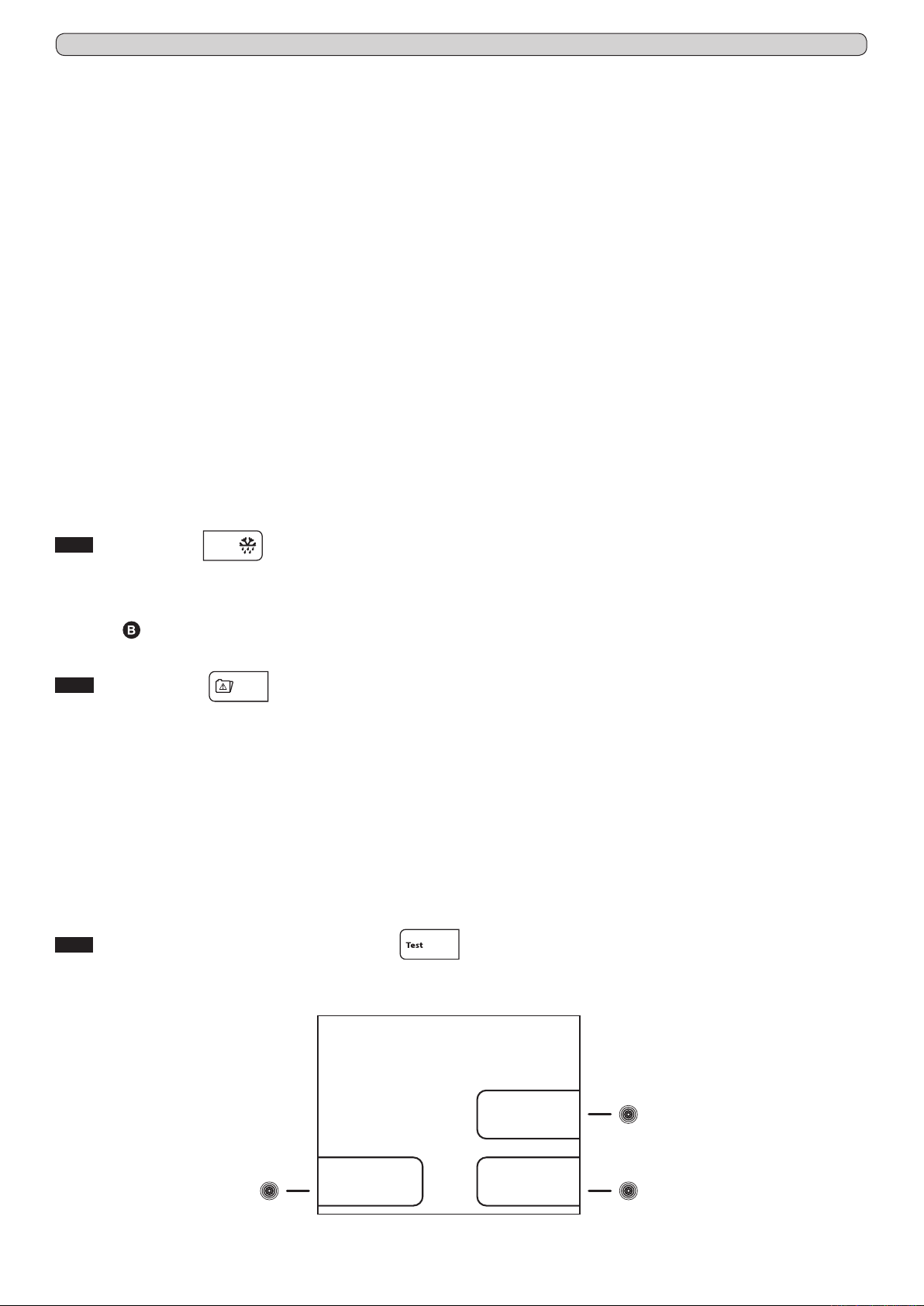
8.3.2.5 Defrosting (touch-button (6) Fig.13)
All the appliance defrosting are recorded in the defrosting log; on the display are shown the following details:
• date and time of the defrost starting
• the duration of the defrost
• the type of defrost, which is indicated from one of the following codes:
01 - defrost started manually from the specic menu
02 - defrost started after 1 hour from the appliance switch-ON
03 - defrost started after a pre-x working time of the appliance
04 - defrost started after a pre-x working time of the compressor
06 - defrost started from automatic defrost
07 - defrost started because of low evaporator temperature
09 - defrost started from an alarm
• progressive recording number of the defrost
To check the defrosting log, proceed as follow:
- from the datas menu, press the touch-button (6) to access to the DEFROSTING menu
- press the touch-button (5)é and the touch-button (7)ê, to scroll the various defrost reports
- press the ESC touch-button (11) to return back to the previous menu or HOME touch-button (10) to return back to the main
screen-shot
8.3.2.6 Sensors (touch-button (7) Fig.13)
The screen-shot sensors allows to read the actual values of the various sensors installed in the appliance (storage chamber, evaporator, condenser and product simulation if present).
To check the sensor readings, proceed as follow:
- from the datas menu, press the touch-button (7) to access to the SENSORS menu
- press the ESC touch-button (11) to return back to the previous menu or HOME touch-button (10) to return back to the main
screen-shot
8.3.3 Manual defrost
To process a manual defrost, proceed as follow:
- from the main menu screen-shot, press the touch-button (4) to access to the MANUAL DEFROST menu
- press the touch-button (4)YES, to process the manual defrost with visual indication in the main screen-shot through the related icon
- press the touch-button (7)NO, to exit without process the defrost and return back to the main screen-shot
8.3.4 Alarms memory
With this menu is possible to check the latest 30 alarm conditions (and related informations) occurred to the appliance.
To check the alarm log, proceed as follow:
- from the main menu screen-shot, press the touch-button (5) to access to the ALARMS MEMORY menu
- press the touch-button (5)é and the touch-button (7)ê to scroll the alarm log
- press the ESC touch-button (11) to return back to the previous menu or HOME touch-button (10) to return back to the main
screen-shot
NB: For the alarms “Door ajar”, “High temperature”, “Battery level low” and “Expansion Board” it will be recorded even the highest
peak of temperature reached into the appliance during the alarm condition.
For the alarms “Low temperature” it will be recorded even the lowest peak of temperature reached into the appliance during the
alarm condition.
If the alarm condition is still in progress, it appears “in progress”.
In case there are no alarms recorded, the display shows NO DATA.
8.3.5 General test and test for temperatures alarm
To process the testing, proceed as follow:
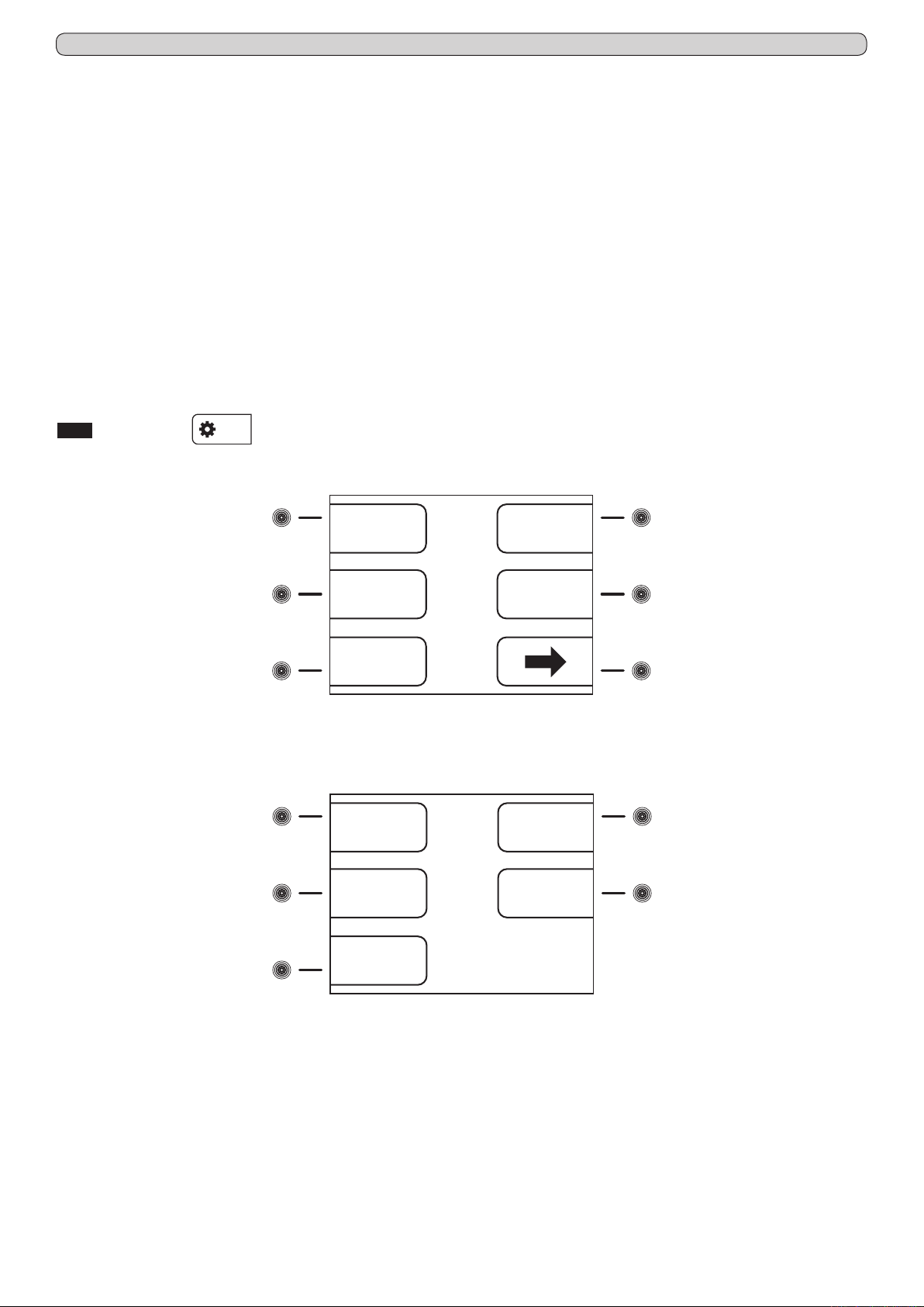
- from the main menu screen-shot, press the touch-button (6) to access to the TEST menu (Fig.14)
(touch-button (4) Fig.12)
(touch-button (5) Fig.12)
(touch-button (6) Fig.12)
TEST
Low temperature
alarm
(4) (7)
General
High temperature
alarm
Fig.14
9
(6)
Page 10
Ver. 0517
- press the touch-button (4) in the TEST screen-shot (Fig.14) to activate the GENERAL test. Through this procedure will be
checked automatically the correct functioning of the battery and battery relay. The buzzer sounds during all the test (6 seconds).
If the test has a positive result, the display shows TEST OK, otherwise the display switch off for a few seconds and automatically
re-starts. Once completed the test, automatically, the display return back to the main screen-shot.
Once the appliance has reached the set temperature, it is possible to make the test temperature. Proceed as follows:
- press the touch-button (6) in the TEST screen-shot (Fig.14) to activate the LOW ALARM TEMPERATURE TEST. The display
shows automatically the temperature that decrease and once reached the limit set for the low alarm temperature, It activates the
buzzer and on the display appears the indication of Low temperature alarm. Press the ESC touch-button (11), the test termi-
nates and the display return back to the main screen-shot.
- press the touch-button (7) in the TEST screen-shot (Fig.14) to activate the HIGH ALARM TEMPERATURE TEST. The display
shows automatically the temperature that increase and once reached the limit set for the high alarm temperature, It activates the
buzzer and on the display appears the indication of Low temperature alarm. Press the ESC touch-button (11), the test termi-
nates and the display return back to the main screen-shot.
NB: During the test, the appliance continue to work normally and the alarm indication is not recorded in the alarms memory.
NB: In case of power blackout, the power is turned by the internal battery. The display will show the red message "POWER
FAILURE ALARM" and the machine automatically shifts in the energy conservation mode. This status is recognized by the inter-
mittently lighting of the display. To silence the buzzer momentarily press the touch (6). To silence the buzzer nally set the value
"0" in the "Reactivation after muting" (Paragraph 8.3.6.5). This procedure will disable the buzzer reactivation of any subsequent
alarms.
8.3.6 Setting menu
(touch-button (7) Fig.12)
To access to the SETTING menu, press the touch-button (7) from the main menu screen-shot. The access is to the rst page of
the menu (Fig.15).
(2)
(3)
(4) (7)
Date and time
Language
Alarms setting
1/2
Ventilation
setting
Download USB
data
Fig.15
(5)
(6)
To access to the second page of the SETTING menu (Fig.16), press the touch-button (7)è from the rst page of the SETTING
menu (Fig.15).
(2)
(3)
(4)
Reactivation
alarm after
muting
Delay of
activation of
temperature
alarm
Delay of
activation of
door ajar alarm
2/2
Codes setting
Calibration
(5)
(6)
Fig.16
To set Date and time see paragraph 8.2.4.
8.3.6.1 Language setting (Fig.10)
To set the display language proceed as follow:
- deactivate the eventual touch-buttons locking protection (see par. 8.1.3)
- press the MENU touch-button (9) to access to the main menu (Fig.12)
- press the touch-button (7) to access to the setting menu (Fig.15)
- press the touch-button (3) to select the menu “Language”
- using the touch-buttons (4)é and (7)ê to set the desired language and then press the ENTER touch-button (12) to conrm
the new settings
10
Page 11
Ver. 0517
8.3.6.2 Alarm setting (touch-button (4) Fig.15)
With this menu is possible to set the desired alarm limits for both the Chamber alarm limits (air temperature into the appliance) and
the Product simulation alarm limits (temperature of the products stored into the appliance simulated with a ballasting of 250 ml of
water or anti-freezing liquid).
To access to the ALARM SETTING menu, press the touch-button (4) while the display shows the rst page of the setting menu
(Fig.15).
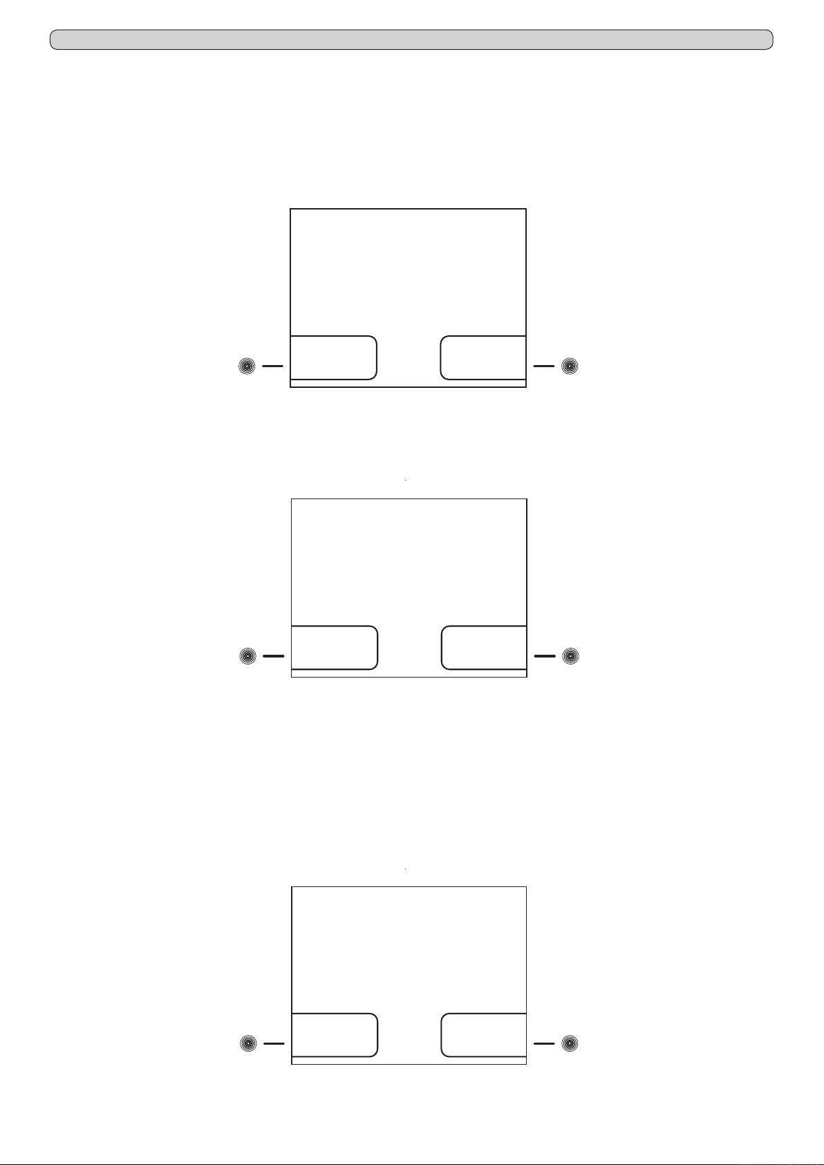
Into the ALARM SETTING menu, there are present 2 sub-menus (Fig.17) that allow to modify the alarm limits both related to the
chamber temperature and to the product simulation (if the optionally available extra sensor is installed).
ALARM SETTINGS
Product
(4) (7)
To set Chamber alarm limits, proceed as follow:
- from the sub-menu ALARM SETTINGS (Fig.17) press the touch-button (4) to access to the screen-shot CHAMBER ALARM
SETTING (Fig.18).
Chamber alarm
simulation
sensor
Fig.17
CHAMBER ALARM
SETTING
Low
(4) (7)
- press the touch-button (4) to access to the screen-shot SETTING CHAMBER LOW TEMPERATURE ALARM
- press the touch-button (4)- and (7)+ to set the desired value
or
- press the touch-button (7) to access to the screen-shot SETTING CHAMBER HIGH TEMPERATURE ALARM
- press the touch-button (4)- and (7)+ to set the desired value
- press the ENTER touch-button (12) to conrm the new setting and the ESC touch-button (11) to return back to the previous
menu or HOME touch-button (10) to return back to the main screen-shot
To set Product simulation sensor alarm limits, proceed as follow:
- from the sub-menu ALARM SETTING (Fig.17) press the touch-button (7) to access to the screen-shot PRODUCT ALARM
SETTING (Fig.19)
temperature
High
temperature
Fig.18
PRODUCT ALARM
SETTING
Low
(4) (7)
- press the touch-button (4) to access to the screen-shot SETTING PRODUCT LOW TEMPERATURE ALARM
temperature
High
temperature
Fig.19
11
Page 12

Ver. 0517
- press the touch-button (4)- and (7)+ to set the desired value
or
- press the touch-button (7) to access to the screen-shot SETTING PRODUCT HIGH TEMPERATURE ALARM
- press the touch-button (4)- and (7)+ to set the desired value
- press the ENTER touch-button (12) to conrm the new setting and the ESC touch-button (11) to return back to the previous
menu or HOME touch-button (10) to return back to the main screen-shot
8.3.6.3 Ventilation setting (touch-button (5) Fig.15)
With this menu is possible to set the desired ventilation level Into the appliance on 3 pre-x levels.
To access to the VENTILATION SETTING, press the touch-button (5) while the display shows the rst page of the setting menu
(Fig.15).
- press the touch-button (4)- and (7)+ to select among the 3 levels of ventilation available:
• LOW: fan working in parallel with the compressor (apart door openings and defrost and some alarm conditions)
• MEDIUM: fan working in parallel with the compressor and with spots functioning during the compressor OFF (apart door
openings and defrost and some alarm conditions)
• HIGH: fan working continuously (apart door openings and defrost and some alarm conditions)
- press the ENTER touch-button (12) to conrm the new setting and the ESC touch-button (11) to return back to the previous
menu or HOME touch-button (10) to return back to the main screen-shot
8.3.6.4 Download USB data (touch-button (6) Fig.15)
With this menu (optionally available) is possible download on a USB memory-stick the data-logged details of the appliance, with
the possibility to select the desired data to download. Following the instructions that will appear on the display, automatically will
be downloaded a le (with .csv extension) on the USB memory-stick, that can be opened with MICROSOFT EXCEL® or whatever
equivalent software compatible with the le extension. If present, the functionality, at the side of the xPRO control panel, there is a
USB port.
The functionality can be even retro-tted ordering the optionally available KIT USB EVERmed and become available after having
correctly installed the software upgrade and the related accessories. The installation instructions are included in the KIT USB EVERmed. Once correctly installed the KIT USB EVERmed, it is possible to access to the Download USB data screen-shot and the
subsequent functionalities.
To download the datas of interest, proceed as follow:
- To access to the DOWNLOAD USB DATA menu, press the touch-button (6) while the display shows the rst page of the setting
menu (Fig.15)
- press the touch-button (5)é and (6)ê to scroll among the list of the possible data to download
- press the touch-button (4)- to clear the data (at the right of the display in correspondence of the data appears “no”) or press the
touch-button (7)+ to select the data (at the right of the display in correspondence of the data appears “yes”)
- all the details with the indication “yes” are ready for the download
- press the ENTER touch-button (12) to conrm and enter in the Download USB screen-shot
- insert the USB memory-stick in the USB port
- the display shows DOWNLOAD HYSTORICAL DATA
- press the ENTER touch-button (12) to conrm and enter in the DATE AND TIME
Set the desired date and time from which download the datas. All the details will be automatically downloaded in the le. To set
the date and time, proceed as follow:
- using the touch-buttons (3)ç and (6)è highlight the position in the calendar or in the clock that should be modied
- using the touch-buttons (4)- and (7)+ to set the desired value
- repeat the last 2 operations for all the numerical values in both calendar and clock, then press the ENTER touch-button (12) to
conrm the details and process the download or the ESC touch-button (11) to return back to the previous menu
- as soon will be nished the download, the display shows END-REMOVE USB
- remove the USB memory-stick and check the le with a suitable PC
8.3.6.5 Reactivation alarm after muting (touch-button (2) Fig.16)
To access to the REACTIVATION ALARM AFTER MUTING, press the touch-button (2) while the display shows the second page
of the setting menu (Fig.16).
- press the touch-button (4)- and (7)+ to set the desired value (expressed in seconds, max. 900) that has to pass from the automatic reactivation of the acoustic alarm after the acoustic alarm signalling has been muted. The reactivation only works in case
the alarm condition persists. If set the value "0", the reactivation is disabled
- press the ENTER touch-button (12) to conrm the new setting and the ESC touch-button (11) to return back to the previous
menu or HOME touch-button (10) to return back to the main screen-shot
8.3.6.6 Temperature alarm activation delay (touch-button (3) Fig.16)
To access to the DELAY OF ACTIVATION OF TEMPERATURE ALARM, press the touch-button (3) while the display shows the
second page of the setting menu (Fig.16).
- press the touch-button (4)- and (7)+ to set the desired value (expressed in seconds, max. 900) that has to pass from the starting of the alarm condition of a temperature alarm till its signalling on the display and through the buzzer
- press the ENTER touch-button (12) to conrm the new setting and the ESC touch-button (11) to return back to the previous
menu or HOME touch-button (10) to return back to the main screen-shot
12
Page 13
Ver. 0517
8.3.6.7 Door ajar alarm activation delay (touch-button (4) Fig.16)
To access to the DELAY OF ACTIVATION OF DOOR AJAR ALARM, press the touch-button (4) while the display shows the second
page of the setting menu (Fig.16).
- press the touch-button (4)- and (7)+ to set the desired value (expressed In seconds, max. 600) that has to pass from the opening of the door till its signalling on the display and through the buzzer
- press the ENTER touch-button (12) to conrm the new setting and the ESC touch-button (11) to return back to the previous
menu or HOME touch-button (10) to return back to the main screen-shot
8.3.6.8 Codes setting (touch-button (5) Fig.16)
From this menu is possible to customize the 2 appliance access codes. The ON/OFF code, which is required every time that it is
needed to switch the appliance ON or OFF (factory code 0050). The Keyboard blocking code, which has to be entered every time
that the appliance has been unused for 5 minutes (factory code 0010).
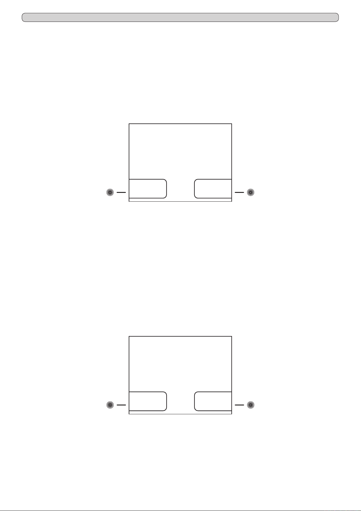
To access to the screen-shot ACCESS CODE SETTING (Fig.20), press the touch-button (5) while the display shows the second
page of the setting menu (Fig.16).
Fig.20
ACCESS CODE
SETTING
(4) (7)
To set a new ON/OFF code, proceed as follow:
- press the touch-button (4) to access to the screen-shot ON/OFF CODE
- using the touch-buttons (3)ç and (6)è highlight the position in the code that should be modied
- using the touch-buttons (4)- and (7)+ to set the desired value
- press the ENTER touch-button (12) to conrm the new setting and the ESC touch-button (11) to return back to the previous menu
To set a new Keyboard blocking code, proceed as follow:
- press the touch-button (4) to access to the screen-shot KEYBOARD BLOCKING CODE
- using the touch-buttons (3)ç and (6)è highlight the position in the code that should be modied
- using the touch-buttons (4)- and (7)+ to set the desired value
- press the ENTER touch-button (12) to conrm the new setting and the ESC touch-button (11) to return back to the previous menu
NB: Setting the value "9999" function will be disabled.
8.3.6.9 Calibration (touch-button (6) Fig.16)
From this menu is possible to manually calibrate 2 sensors of the appliance. The Chamber sensor is the one acquiring the tempera
ture into the appliance, while the Product simulation sensor (optionally available) simulate the temperature of the products stored into
the appliance with a ballasting of 250 ml of water (or anti-freezing liquid). Through this menu is possible to adjust the reading of the
sensors according to reading of external comparison thermometers, data loggers, thermocouples or personal wishes. To access to the
CALIBRATION SETTING (Fig.21), press the touch-button (6) while the display shows the second page of the setting menu (Fig.16)
ON/OFF code
Keyboard
blocking code
Fig.21
CALIBRATION
SETTING
-
Product
(4) (7)
To set a new calibration for the Chamber sensor, proceed as follow:
- press the touch-button (4) to access to the screen-shot CALIBRATION CHAMBER SENSOR
- press the touch-button (4)- and (7)+ to increase (max + 10°C) or lower (min -10°C) the calibration value highlited
- press the ENTER touch-button (12) to conrm the new setting and the ESC touch-button (11) to return back to the previous
menu or HOME touch-button (10) to return back to the main screen-shot
To set a new calibration for the Product simulation sensor (optionally available), proceed as follow:
- press the touch-button (4) to access to the screen-shot CALIBRATION PRODUCT SENSOR
- press the touch-button (4)- and (7)+ to increase (max +10°C) or lower (min -10°C) the calibration value highlited
- press the ENTER touch-button (12) to conrm the new setting and the ESC touch-button (11) to return back to the previous
menu or HOME touch-button (10) to return back to the main screen-shot
Chamber sensor
simulation
sensor
13
Page 14

Ver. 0517
8.4 OPERATION OF THE TEMPERATURE CHART RECORDER
8.4.1 Description of the temperature chart recorder (Fig.22)
The appliance may be fitted (present if ordered is some series), with the temperature chart recorder, recording on paper charts the appliance internal temperature.
The temperature recorder is available in different temperature ranges according
to the model on which it is installed:
- Range : -10°C / +40°C
- Range : -35°C / +15°C
- Range : -50°C / +50°C
The survey of the chamber temperature is done with a sensor independent
from the control panel sensor, whiles the recording, weekly operation, is on
paper charts with an ink-tip. The temperature recording is granted even during
power failure periods thanks to the battery powering of the recording device.
The battery is 1,5V, AA type. A perspex cover allows checking the diagrams but
at the same time it protects them against tampering of unauthorized personnel
thanks to the key locks safety.
8.4.1.1 Paper chart replacement
- Open the perspex cover
- Unscrew the fixing nut
- Lift gently the metal arm on which is fitted the ink-tip
- Remove the installed paper chart, paying attention at the 2 metal edges surrounding
the chart that keep it in position
- Insert the new paper chart, paying attention to insert it into the central hinge and
into the 2 metal edges surrounding the chart
- Lower gently the metal arm on which is fitted the ink-tip in order to return it in the
original position
- Drive the paper chart in order to position the ink-tip writing point in the exact point
from which it has to start to record the temperature, paying attention to do not write
on the diagram. In order to choose the exact recording start point, refer to the days
and times printed on the chart itself
- Screw the fixing nut
- Close the perspex cover
Fig.22
8.4.1.2 Ink-tip replacement
- Open the perspex cover
- Lift gently the metal arm on which is fitted the ink-tip
- Remove, pulling, the ink-tip from the metal arm
- Insert the new ink-tip on the metal arm paying attention to the guideways on the
ink-tip itself. Push until reach the limit-stop
- Lower gently the metal arm on which is fitted the ink-tip in order to return it in the
original position
- Close the perspex cover
8.4.1.3 Battery replacement
- Open the perspex cover
- Unscrew the fixing nut
- Lift gently the metal arm on which is fitted the ink-tip
- Remove the installed paper chart, paying attention at the 2 metal edges surrounding the chart
that keep it in position
- Pull the central hinge on which was screwed the nut, and at the same time moving slightly up
and down to make easier the extraction of the clockwise mechanism
- Replace the battery in the rear side of the clockwise mechanism paying attention to the battery
polarity
- Insert the clockwise mechanism in the hole left on the chart recorder, simply making pressure
on the mechanism
- Insert the paper chart, paying attention to insert it into the central hinge and into the 2 metal
edges surrounding the chart
- Lower gently the metal arm on which is fitted the ink-tip in order to return it in the original position
- Drive the paper chart in order to position the ink-tip writing point in the exact point from which it
has to start to record the temperature, paying attention to do not write on the diagram. In order
to choose the exact recording start point, refer to the days and times printed on the chart itself
- Screw the fixing nut
- Close the perspex cover
14
Page 15

Ver. 0517
8.5 OPERATION OF THE DIGITAL PRINTER
8.5.1 Description of the digital printer
The appliance may be fitted (present if ordered in some series), with the temperature digital printer.
The digital printer records the temperature in an internal non-volatile memory the temperature of the appliance. The recording periods
and intervals are fully adjustable and can be easily set through the printer soft-touchpads and the wide display (with clear written
indications). Then, the temperature trends can be printed on paper, selecting among 3 printing modes according to the need, online
(printing out at fix intervals), on daily basis (once per day) or an historical report of all the datas acquired.
The survey of the chamber temperature is done with a sensor independent from the control panel sensor. To increase the safety
level, it is included an alarm for sensor failure. The printing is ink-free on thermal paper.
For more detailed information, please refer to the specific booklet (included among the instructions if the printer is present).
15
Page 16

EVERmed Srl: Via Galileo Galilei, n° 2 - 46020 Motteggiana (MN) ITALY
Tel. +39 0376 550828 - Fax +39 0376 550831
www.evermed.it - e-mail: [email protected]
 Loading...