

Page 1
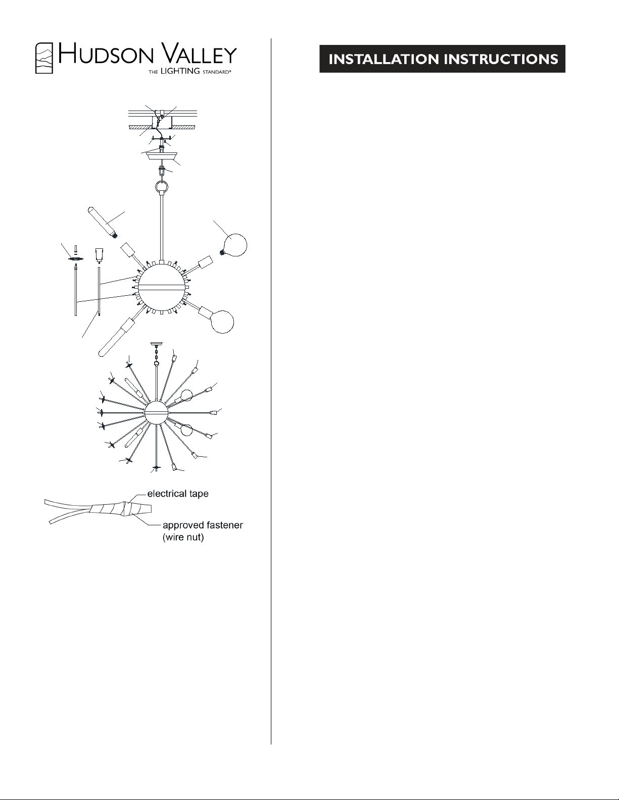
5046, 5060
G40 Lamp 60W
Ring
Canopy
Crossbar
Outlet box
Screw
Screwcollar loop
Grounding screw
Safety cable
Cable clamp
A
B
T10 Lamp 75W
A
A
A
A
A
A
A
B
B
B
B
B
B
B
Ø3.15" Round
Clear glass
37pcs
1.5" Square glass
36pcs around
A
GENERAL
Thank you for purchasing our lighting fixture.
Please clean with a soft, dry cloth ONLY! Do not
use cleansers.
www.hudsonvalleylighting.com
1. To ensure successful installation, the following instructions and diagram(s) should
be read and understood.
2. All electrical connections must be made in accordance with the National Electric
code and local codes and ordinances. If you are uncertain how to install electrical
wiring and lighting fixtures, secure the services of a qualified licensed electrician.
TOOLS NEEDED
Blade screwdriver, phillips screwdriver, slip joint pliers or small adjustable wrench,
wire cutter/stripper, electrical current tester, stepladder and electrical tape.
INSTALLATION PREPARATION
1. TURN OFF THE ENTIRE ELECTRICAL CIRCUIT TO WHICH THE
LIGHTING FIXTURE IS TO BE ATTACHED. Turn circuit breaker to the off
position or completely remove the fuse controlling the circuit.
2. If an existing fixture is being replaced, remove it and note to which of the wires in the
outlet box the fixture was attached. DO NOT SEPARATE MULTIPLE TWISTED
WIRES THAT MAY BE IN THE BOX. DO NOT DAMAGE THE
INSULATION OF OLDER WIRING. In regular circumstances the BLACK wire will
be the “Hot” lead and the WHITE wire will be the “Neutral” or “Common” lead. A
GREEN or BARE COPPER wire is the “Ground”. In older buildings it is always good
practice to reconfirm the polarity of the wiring.
3. This fixture is designed to be mounted on an octagon box. The box must be securely
mounted to the structure of the building.
FIXTURE INSTALLATION
1. Remove the outlet box from the approved support.
2. Slide crimp type cable clamp onto the safety cable. Feed the SAFETY CABLE down
through one of the holes in the top of the outlet box. Loop the SAFETY CABLE over the
approved support. Feed the SAFETY CABLE back through the top of the box and the
cable clamp. Using the crimping tool, tightly crimp the cable clamp to lock the SAFETY
CABLE in position.
3. Reinstall the outlet box to the approved support.
4. Remove the fixture and parts bag(s) from the carton. Before discarding the carton, double
check packing to make certain that all parts are found.
5. Attach the mounting bar to the outlet box. (The green screw should face out). Pull wires
out of box. Thread the nipple onto the mounting bar.
6. Open end links of chain and attach the chain to the loop. Close the top link of chain. Hang
the fixture on the chain at the desired height. Remove excess chain. Close the bottom link of
chain.
7. Measure 6" of lead wire beyond the end of the chain. Cut off excess wire.
Strip the insulation off the ends of the leads exposing approx. 1/2 " of wire.
Twist the strands of wire together. Push the leads and ground wire up through the
screwcollar loop and nipple and into the outlet box.
8. Fasten the bare ground wire to the green or bare copper wire in the outlet box or the
green screw on the crossbar. NEVER FASTEN THE GROUND WIRE TO THE
BLACK OR "HOT" WIRE ! FAILURE TO FOLLOW THIS INSTRUCTION
COULD RESULT IN SERIOUS INJURY OR DEATH !
9. This fixture has 2 neutral wire (ridges lead). Make sure you connect two fixture
leads with the ridges to the white wire in the outlet box.
Fasten the wires together with an approved fastener (wire nut) Starting about 1" below the
fastener, tightly wrap the connection with electrical tape so that the tape seals the end of the
fastener. Make sure that there is no exposed wire or strands that could cause a
dangerous short circuit !
10. This fixture has 2 live wire(smooth leads). Make sure you connect two
smooth fixture lead to the black wire in the outlet box. Fasten the joined wires as in
step 6.
11. Slide the canopy and screwcollar ring up the chain and secure the canopy to the ceiling.
12. Attached the glass to the stem then thread to the fixture, each type stem have different
thread for match different fitter, thread the stem into the right fitter. Make sure you have
stem on every fitters.
13. Install the lamp(s) The fixture is rated for 60 watt type G40 and 75W watt type T10
lamp(s). DO NOT EXCEED RECOMMENDED WATTAGE !
14. Restore power to circuit at breaker or fuse box.
Page 2
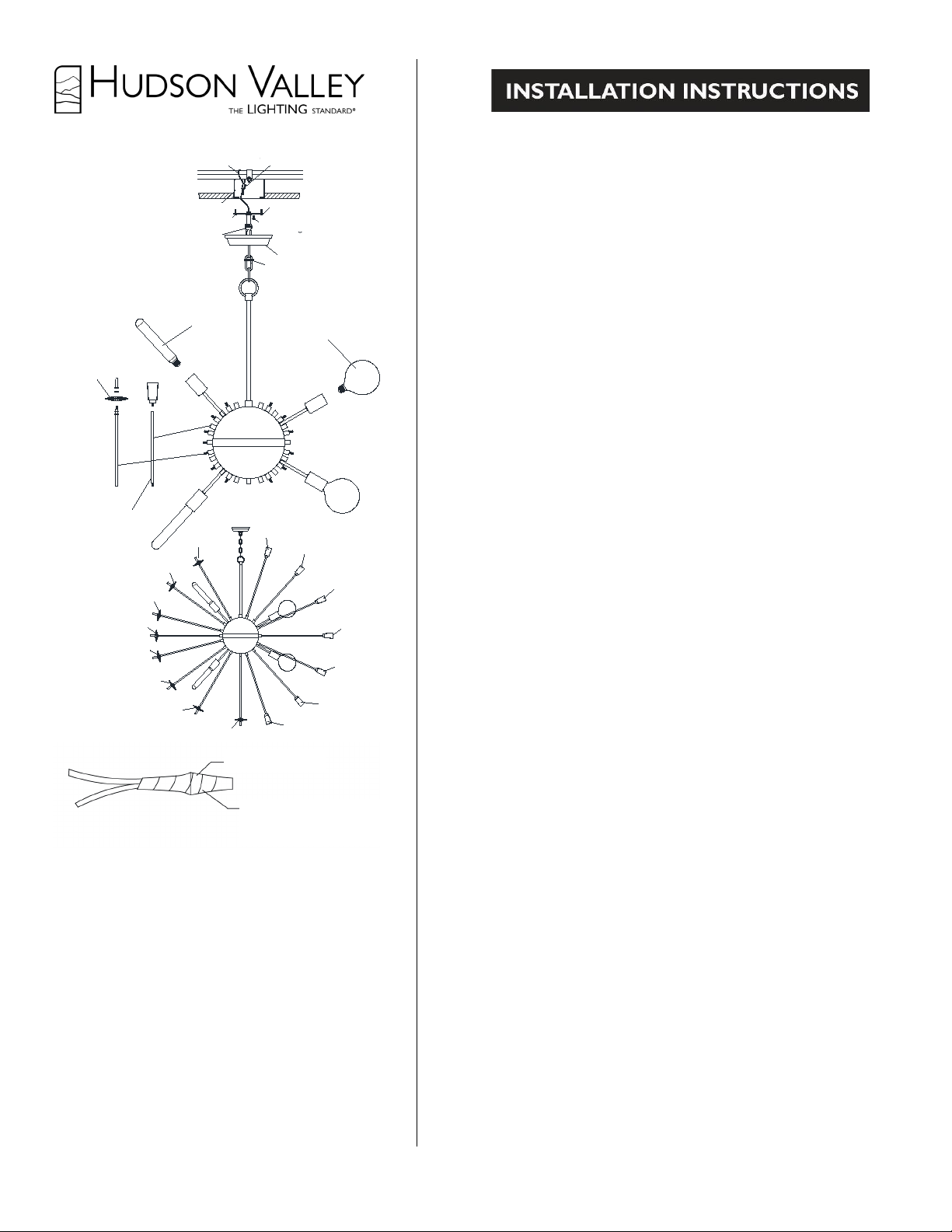
5046, 5060
G40 Lamp 60W
Ring
Canopy
Crossbar
Outlet box
Screw
Screwcollar loop
Grounding screw
Safety cable
Cable clamp
A
B
T10 Lamp 75W
A
A
A
A
A
A
A
B
B
B
B
B
B
B
Ø3.15" Round
Clear glass
37pcs
1.5" Square glass
36pcs around
A
REMARQUES GÉNÉRALES
pe existante, noter à quels fils de la boîte de connexion ladite
POURRAIENT SE TROUVER DANS LA BOÎTE. NE PAS ENDOMMAGER L'ISOLATION DE
constitue la mise à la "terre" ("Ground"). Dans les maisons plus anciennes il vaut toujours mie
nnexion du
uveau sur la boîte et l
tio
boîte de connexion. (La vis verte face au sol). Retirer les fils
maillon de la chaîne. Suspendre la lampe à la chaîne à la hauteur voulue. Enlever l’excédent de
Unir les fils entre eux. Faire passer les fils et le fil de mise à terre par la bague de serrage à ann
8. Relier le fil nu de mise à terre au fil vert ou de cuivre nu dans la boîte de connexion ou le fi
HASE
RESPECT DE CETTE RECOMMANDATION PEUT CONDUI
s’assurer de relier deux fils striés aux fils blancs dan
assurer de ne laisser aucune portion de fils ou de filaments
s tension (fils lisses). S’assurer de relier deux fils lisses au fil noir da
iculi
qui correspond à la douille appropriée, visser la tige dans la douille appropriée. S’assurer d’avo
de
T10. NE PAS DÉPASSER CETTE TENSION RECOMMANDÉE
14. Rebrancher le courant au disjoncteur ou à la boîte à fusibles.
Verre rond
incolore
8cm (3.15”)
37 pcs
Vis de mise à terre
Barre transversale
Serre-câble
Câble de retention
Vis
Boîte de connexion
Bague de serrage
Bague
Cache-piton
Ampoule
60W T10
Ampoule 60W G40
Verre carré
36pcs
Connecteur approuvé
(borne
Ruban isolant
1. Pour assurer la réussite de l'installation de ce dispositif d'éclairage, il est nécessaire de lire
et de comprendre les instructions et diagramme(s) suivants.
2. Tous les raccordements électriques doivent être réalisés conformément au code
avec boucle
3,8cm (1.5”)
électrique national ainsi qu'aux codes locaux et aux ordonnances. Si vous n'êtes pas sûr de la
manière de réaliser les raccordements électriques et d'installer le dispositif d'éclairage dans
les règles de l'art, assurez-vous les services d'un électricien qualifié autorisé.
OUTILS REQUIS
Tournevis plat, tournevis Phillips, pince multiprise ou petite clé à molette, pince à
couper/dénuder les fils, testeur de courant électrique, escabeau et ruban isolant adhésif.
PRÉPARATION DE L'INSTALLATION
1. DÉBRANCHER COMPLÈTEMENT LE CIRCUIT ÉLECTRIQUE AUQUEL LE
DISPOSITIF D'ÉCLAIRAGE DOIT ÊTRE RELIÉ. Placer le coupe-circuit approprié en
position "arrêt" ("off") ou retirer complètement le fusible contrôlant le circuit en question.
2. S'il s'agit de remplacer une lam
lampe était reliée après l'avoir démontée. NE PAS DÉCONNECTER D'AUTRES FILS QUI
VIEUX FILS. Normalement le fil NOIR conduit la "phase" ("Hot") et le fil BLANC est le
conducteur "neutre" ("Neutral") ou "commun" ("Common"). Un fil VERT ou de CUIVRE NU
vérifier la polarité du câblage.
3. Ce dispositif d'éclairage est conçu pour être monté sur une boîte de connexion standard
ronde ou octogonale. La boîte doit être fixée d'une manière sûre à la structure de la maison.
INSTALLATION DU DISPOSITIF D'ÉCLAIRAGE 1. Retirer la boîte de co
support approuvé.
2. Glisser le serre-câble sur le câble de retention. Passer le CÀBLE DE RETENTION
par un des trous sur la boîte de connexion. Passer le CÀBLE DE RETENTION par-
dessus le support approuvé. Repasser le CÀBLE DE RETENTION de no
serre-câble. Utilisant la pince à sertir, sertir fermement le serre-câble pour bloquer en posi
CÂBLE DE RETENTION.
3. Réinstaller la boîte de connexion au support approuvé.
4. Retirer le dispositif et le(s) sachet(s) du carton. Avant de jeter le carton, s'assurer de la
présence de
tous les composants.
5. Fixer la barre transversale à la
boîte. Visser le téton à la barre transversale.
6. Ouvrir le dernier maillon de la chaîne et relier la chaîne à l’anneau. Fermer le premier
chaîne. Fermer le dernier maillon de la chaîne.
7. Mesurer 15,2cm (6”) de fil conducteur au-delà de l’extremité de la chaîne. Couper
l’excédent de fil. Dénuder l’isolation à la fin des fils en exposent environ 1,3cm (1/2”) du fil.
de raccordement)
Merci d'avoir choisi notre dispositif d'éclairage.
À nettoyer UNIQUEMENT avec un chiffon doux
et sec! Ne pas utiliser de détergents.
www.hudsonvalleylighting.com
et le téton dans la boîte de connexion.
à la vis verte sur la barre transversale.
NE JAMAIS RELIER LE FIL DE MISE À LA TERRE AU FIL NOIR OU DE "P
("HOT")! LE NONÀ DE GRAVES BLESSURES OU À LA MORT!
9. Ce dispositif a 2 fils neutres (fils striés),
boîte de connexion. Unir les fils entre eux à l'aide d'un connecteur approuvé (borne de
raccordement). En commençant environ 2 ½ cm (1") en-dessous de la borne, envelopper la
connexion à l'aide de ruban isolant bien serré de manière à ce que le ruban recouvre aussi
l'extrémité de la borne. S'
découverte, qui pourrait causer un dangereux court-circuit !
10. Ce dispositif a 2 fils sou
boîte de connexion. Unir les fils entre eux comme décrit sous 9.
11. Glisser le cache-piton et la bague de serrage le long de la chaîne et sécuriser le
cache-piton au plafond.
12. Fixer le verre à la tige et visser au dispositif, chaque type de tige a un pas de visse part
une tige sur chaque douille.
13. Installer la(les) ampoule(les). Le dispositif est conçu pour une/des ampoule(s) de 60W
G40 et 75W de type
 Loading...