

Page 1
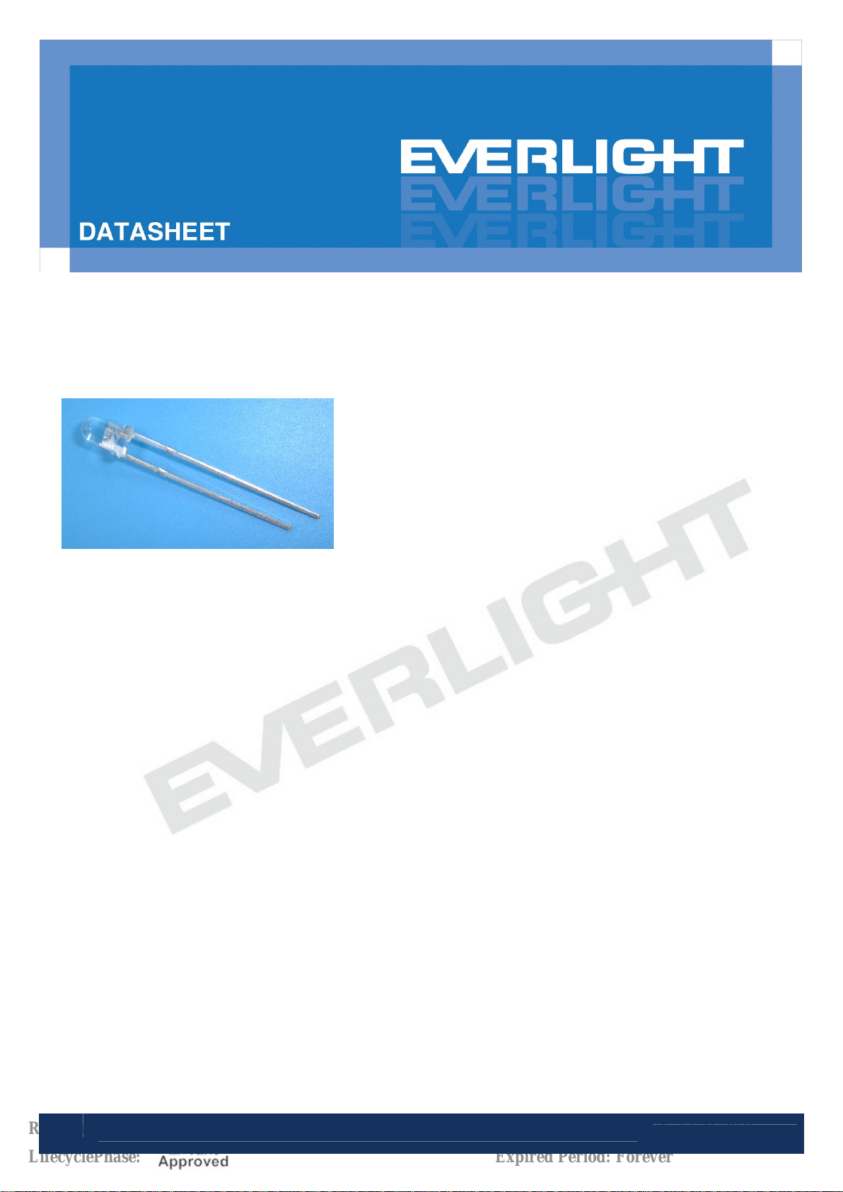
LAMP
204-15UTC/S400-X9
Features
• Popular T-1 round package
• High luminous power
• Typical chromaticity coordinates x=0.29, y=0.28
according to CIE1931
• Bulk, available taped on reel.
• ESD-withstand voltage: up to 4KV
• The product itself will remain within RoHS compliant version
Description
• The series is designed for application required high luminous intensity.
• The phosphor filled in the reflector converts the blue emission of InGaN chip to ideal white.
Applications
• Message panels
• Optical Indicators
• Backlighting
• Marker Lights
1
Revision : 3
Copyright © 2010, Everlight All Rights Reserved. Release Date : Apr.25.2012. Issue No: DLE-0001736_Rev.3
LifecyclePhase:
Release Date:2012-04-26 13:21:29.0
Expired Period: Forever
www.everlight.com
Page 2
DATASHEET
LAMP
204-15UTC/S400-X9
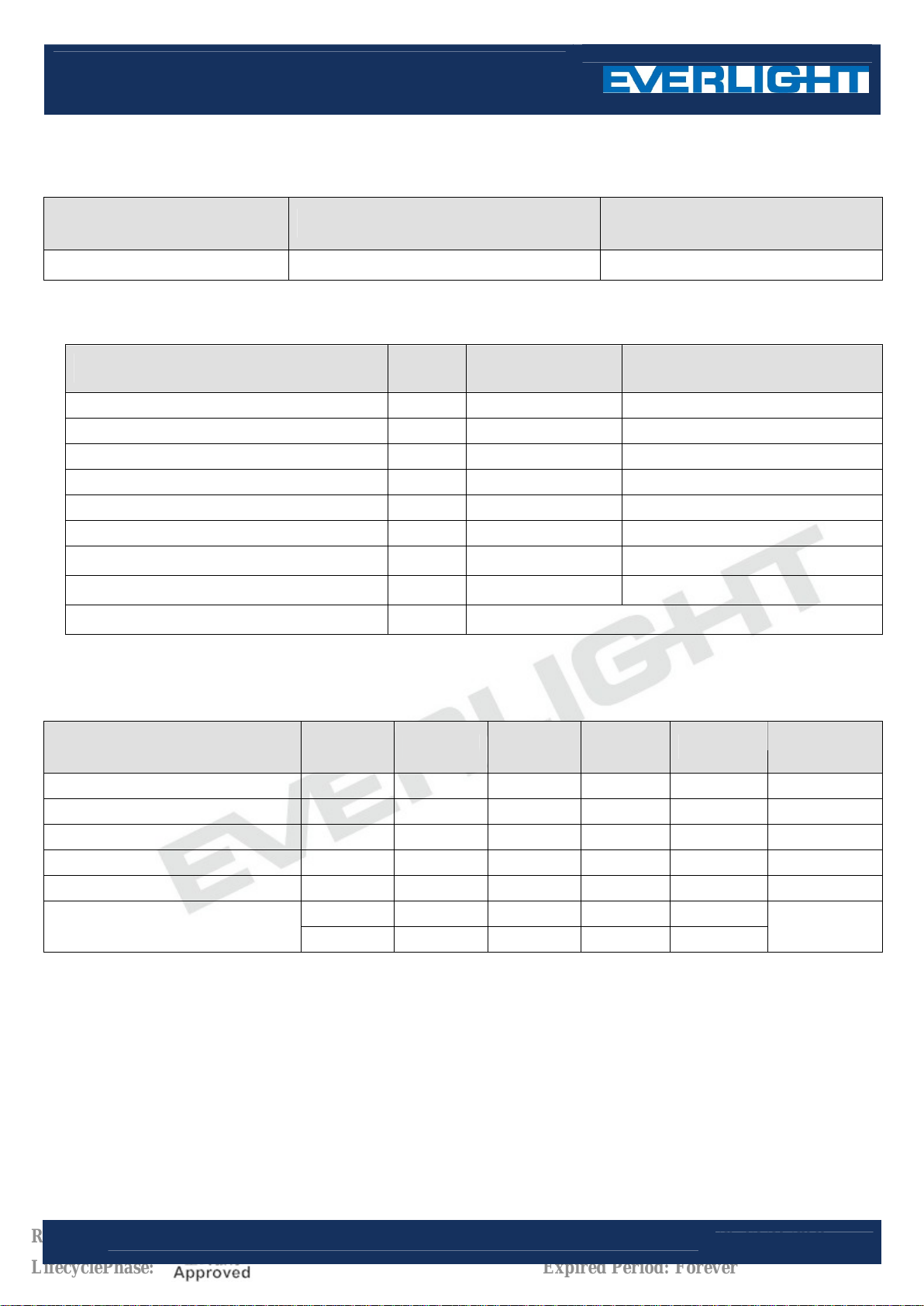
Device Selection Guide
Chip
Materials
Emitted Color Resin Color
InGaN White Water Clear
Absolute Maximum Ratings (Ta=25 )℃
Parameter Symbol Rating Unit
Continuous Forward Current I
Peak Forward Current (Duty 1/10 @ 1KHZ) I
Reverse Voltage V
Power Dissipation P
Operating Temperature Topr
Storage Temperature Tstg
ESD ESD
Zener Reverse Current I
Soldering Temperature
Tsol 260
FP
F
R
d
z
HBM
30
100
5
110
-40 ~ +85
-40 ~ +100
4K
100 mA
℃ for 5 sec.
mA
mA
V
mW
℃
℃
V
Electro-Optical Characteristics (Ta=25 )℃
Parameter Symbol Min. Typ. Max. Unit Condition
Forward Voltage
Zener Reverse Voltage
Reverse Current
Luminous Intensity
Viewing Angle
Chromaticity Coordinates
V
F
Vz
I
R
I
V
2θ1/2
x
y
2.8 ----- 3.6
5.2 ----- -----
----- ----- 50
2850 ---- 7150
---- 25 ----
---- 0.29 ----
---- 0.28 ----
V I
=20mA
F
V Iz=5mA
μA VR=5V
mcd I
deg I
----
----
=20mA
F
=20mA
F
I
=20mA
F
2
Revision : 3
Copyright © 2010, Everlight All Rights Reserved. Release Date : Apr.25.2012. Issue No: DLE-0001736_Rev.3
LifecyclePhase:
Release Date:2012-04-26 13:21:29.0
www.everlight.com
Expired Period: Forever
Page 3
DATASHEET
LAMP
204-15UTC/S400-X9
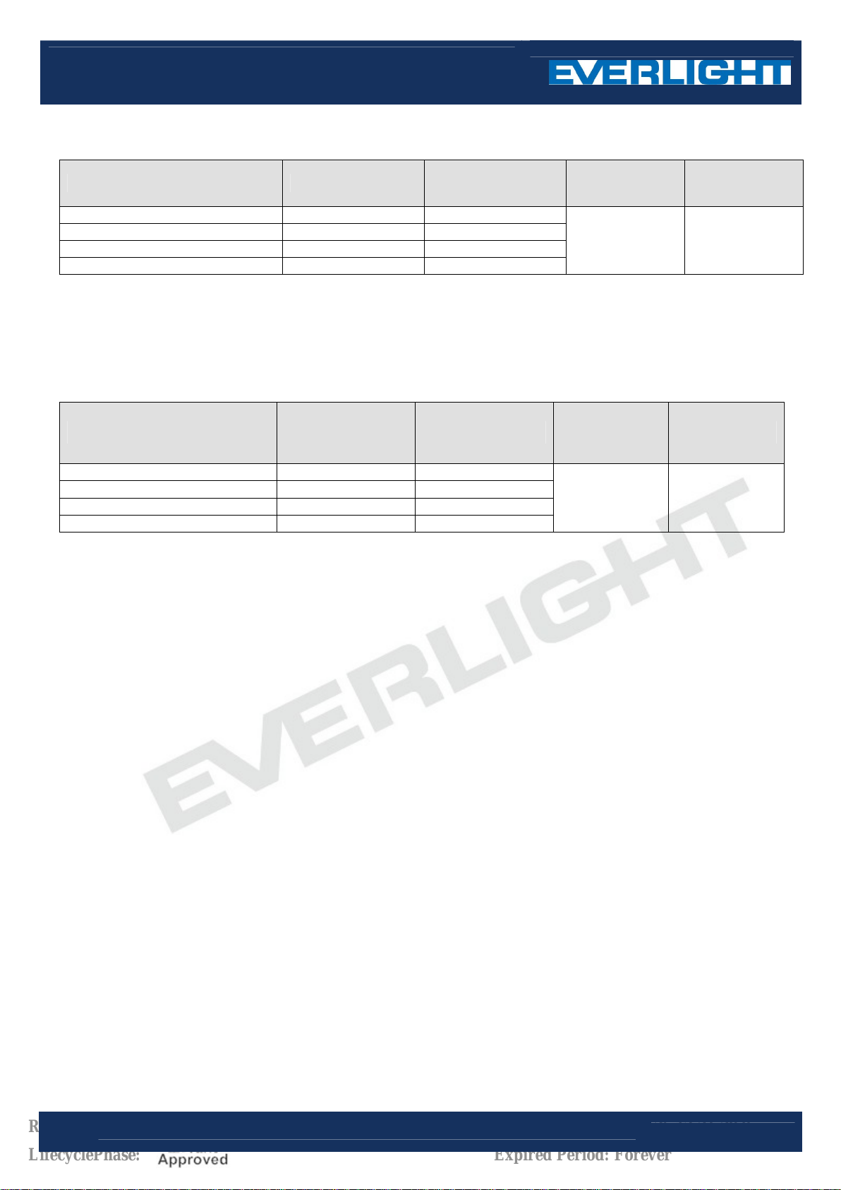
Bin Range of Luminous Intensity
Bin Code Min. Max. Unit Condition
G2 2850 3600
H1 3600 4500
H2 4500 5650
J1 5650 7150
Note:
Tolerance of Luminous Intensity: ±10%
Forward Voltage Combination
Bin Code Min. Max. Unit Condition
mcd I
=20mA
F
0 2.8 3.0
1 3.0 3.2
2 3.2 3.4
3 3.4 3.6
Note:
Measurement Uncertainty of Forward Voltage:±0.1V
V I
=20mA
F
3
Revision : 3
Copyright © 2010, Everlight All Rights Reserved. Release Date : Apr.25.2012. Issue No: DLE-0001736_Rev.3
LifecyclePhase:
Release Date:2012-04-26 13:21:29.0
www.everlight.com
Expired Period: Forever
Page 4

DATASHEET
LAMP
204-15UTC/S400-X9
CIE Chromaticity Diagram
0.90
520
0.80
0.70
0.60
550
570
500
0.50
0.40
CIE (Y)
0.30
D
600
C
0.20
480
B
A
0.10
470
0.00
0.10 0.30 0.50 0.700.00 0.20 0.40 0.60 0.80
CIE (X)
Color Ranks (IF=20mA,Ta=25℃)
Color Ranks
A1
A2
B1
B2
C1
C2
D1
D2
Note:
Measurement uncertainty of the color coordinates:±0.01
4
Revision : 3
Copyright © 2010, Everlight All Rights Reserved. Release Date : Apr.25.2012. Issue No: DLE-0001736_Rev.3
Min. Max. Min. Max.
0.215 0.245 0.155 0.215
0.245 0.260 0.185 0.245
0.260 0.275 0.215 0.275
0.275 0.290 0.245 0.295
0.290 0.305 0.275 0.315
0.305 0.320 0.295 0.335
0.320 0.340 0.315 0.355
0.340 0.360 0.335 0.385
LifecyclePhase:
CIE X
CIE Y
Release Date:2012-04-26 13:21:29.0
www.everlight.com
Expired Period: Forever
Page 5
DATASHEET
100
LAMP
204-15UTC/S400-X9
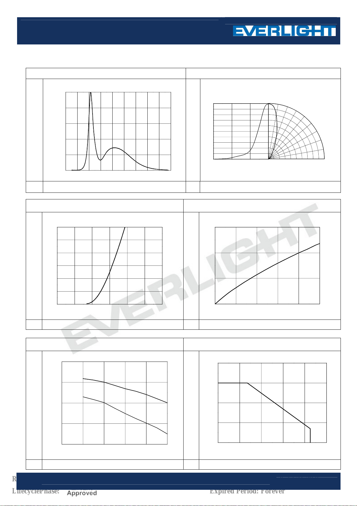
Typical Electro-Optical Characteristics Curves
Relative Intensity vs. Wavelength (Ta=25 )℃ Directivity (Ta=25 )℃
1.0
0.8
0.6
0.4
1.0
0.5
O
90
O
60
O
O
30
O
0
10
O
20
O
30
O
40
O
50
60
Radiation Angle
Relative Intensity (a.u.)
0.2
0.0
350 400 450 500 550 600 650 700 750 800
0
0
0.5
Wavelength (nm) Relative Intensity (a.u.)
Forward Current vs. Forward Voltage (Ta=25 )℃ Relative Intensity vs. Forward Current (Ta=25 )℃
30
25
20
15
1.5
1.0
O
70
1.0
O
O
80
O
90
10
5
Forward Current (mA)
0
1.5 2.0 2.5 3.0 3.5 4.0 4.5
Forward Voltage (V) Forward Current (mA)
Chromaticity Coordinate vs. Forward Current(Ta=25 )℃
0.300
0.290
x
y
0.280
0.270
Chromaticity Coordinate
0.260
0 10 20 30 40 50
0.5
Relative Intensity(a.u.)
0.0
0 5 10 15 20 25
Forward Current vs. Ambient Temp.
40
30
20
10
Forward Current (mA)
0
0 20 40 60 80
5
Revision : 3
LifecyclePhase:
Forward Current (mA)
Copyright © 2010, Everlight All Rights Reserved. Release Date : Apr.25.2012. Issue No: DLE-0001736_Rev.3
Release Date:2012-04-26 13:21:29.0
Ambient Temperature Ta(
Expired Period: Forever
℃)
www.everlight.com
Page 6
DATASHEET
LAMP
204-15UTC/S400-X9
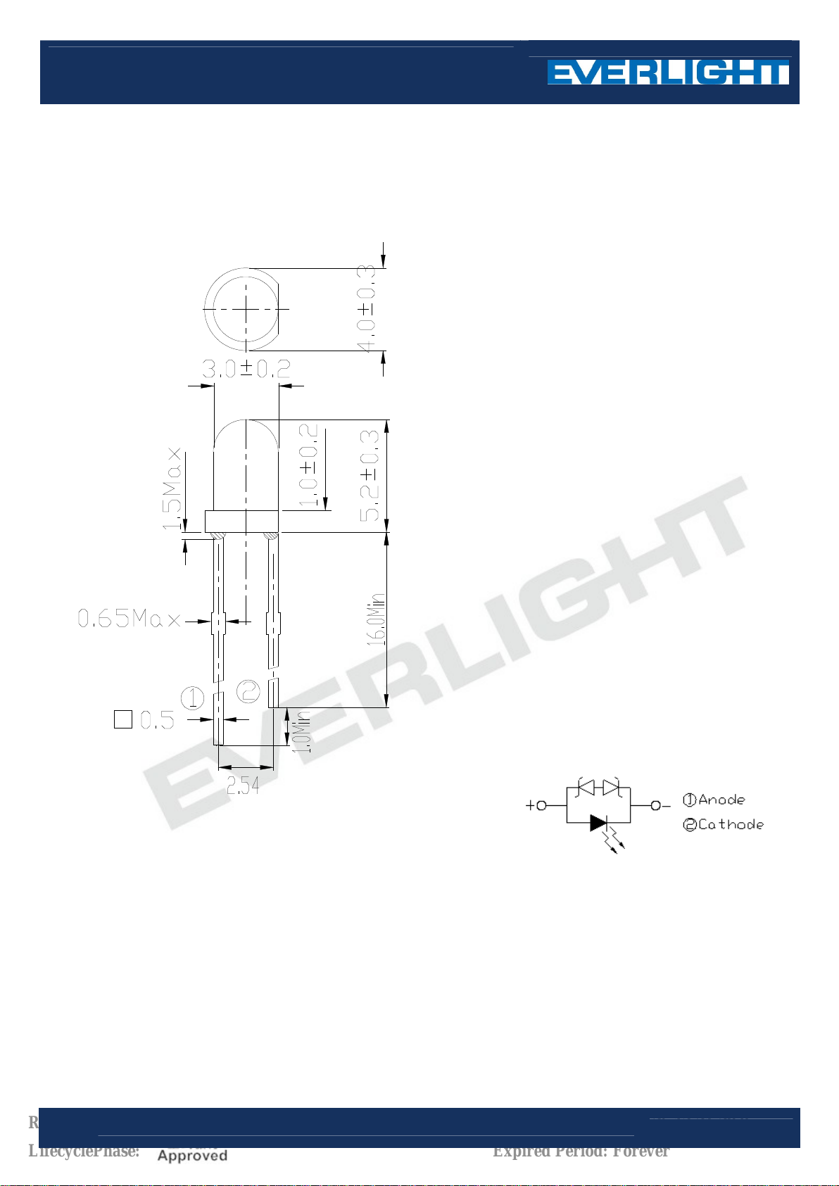
Package Dimension
Note: Note:
1.All dimensions are in millimeters, and tolerance is 0.25mm except being specified.
2.Lead spacing is measured where the lead emerges from the package.
3.Protruded resin under flange is 1.5mm Max. LED.
6
Revision : 3
Copyright © 2010, Everlight All Rights Reserved. Release Date : Apr.25.2012. Issue No: DLE-0001736_Rev.3
LifecyclePhase:
Release Date:2012-04-26 13:21:29.0
www.everlight.com
Expired Period: Forever
Page 7
DATASHEET
LAMP
204-15UTC/S400-X9
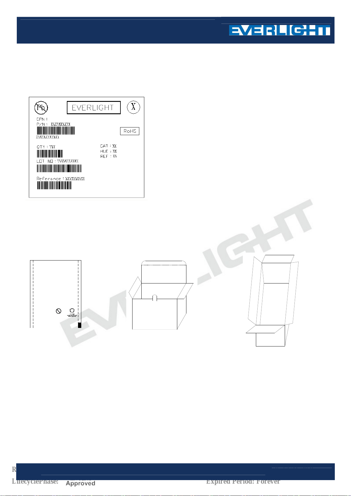
Moisture Resistant Packing Materials
Label Explanation
‧CPN: Customer’s Production Number
‧P/N : Production Number
‧QTY: Packing Quantity
‧CAT: Ranks of Luminous Intensity and Forward Voltage
‧HUE: Color Rank
‧
REF: Reference
LOT No: Lot Number‧
Packing Specification
■ Anti-electrostatic bag ■ Inner Carton ■ Outside Carton
Pb
EL ECTROSTATIC ELECTRONAGNETIC
MAGNETIC OR RADIOACTIVE RELDS
anti-static for 750
■ Packing Quantity
1. Min 200 to Max 1000 PCS/1 Bag, 5 Bags/1 Inner Carton
2. 10 Inner Cartons/1 Outside Carton
7
Revision : 3
Copyright © 2010, Everlight All Rights Reserved. Release Date : Apr.25.2012. Issue No: DLE-0001736_Rev.3
LifecyclePhase:
Release Date:2012-04-26 13:21:29.0
www.everlight.com
Expired Period: Forever
Page 8
DATASHEET
LAMP
204-15UTC/S400-X9
Notes
1. Lead Forming
During lead formation, the leads should be bent at a point at least 3mm from the base of the epoxy bulb.
Lead forming should be done before soldering.
Avoid stressing the LED package during leads forming. The stress to the base may damage the LED’s
characteristics or it may break the LEDs.
Cut the LED leadframes at room temperature. Cutting the leadframes at high temperatures may cause failure of
the LEDs.
When mounting the LEDs onto a PCB, the PCB holes must be aligned exactly with the lead position of the LED.
If the LEDs are mounted with stress at the leads, it causes deterioration of the epoxy resin and this will degrade
the LEDs.
2. Storage
The LEDs should be stored at 30°C or less and 70%RH or less after being shipped from Everlight and the
storage life limits are 3 months. If the LEDs are stored for 3 months or more, they can be stored for a year in a
sealed container with a nitrogen atmosphere and moisture absorbent material.
Please avoid rapid transitions in ambient temperature, especially, in high humidity environments where
condensation can occur.
3. Soldering
Careful attention should be paid during soldering. When soldering, leave more then 3mm from solder joint to
epoxy bulb, and soldering beyond the base of the tie bar is recommended.
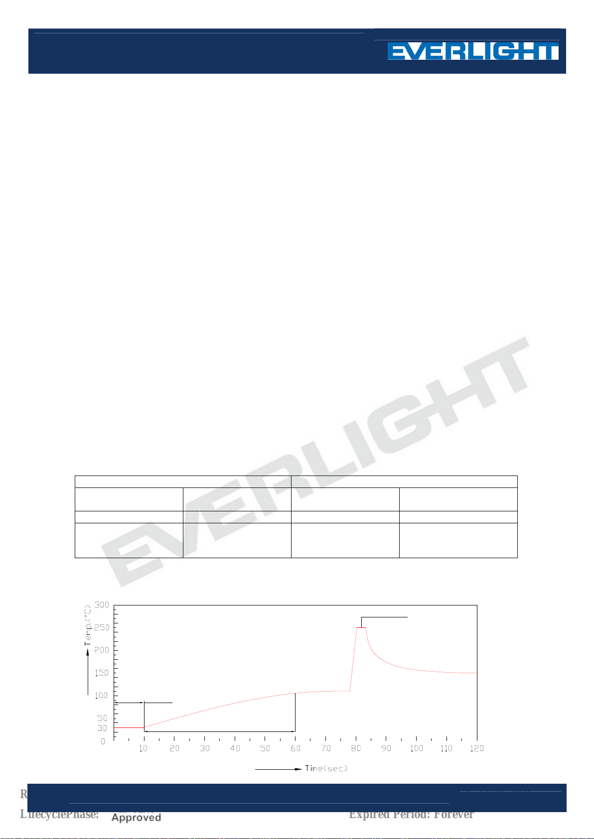
Recommended soldering conditions:
Hand Soldering DIP Soldering
300 Max. (30W
Temp. at tip of iron
Soldering time 3 sec Max. Bath temp. & time 260 Max., 5 sec Max
Distance 3mm Min.(From
Recommended soldering profile
℃
Max.)
solder joint to epoxy
bulb)
Preheat temp.
Distance 3mm Min. (From solder
laminar wave
100 Max. (60 sec
℃
Max.)
joint to epoxy bulb)
8
Revision : 3
Copyright © 2010, Everlight All Rights Reserved. Release Date : Apr.25.2012. Issue No: DLE-0001736_Rev.3
LifecyclePhase:
Fluxing
Prehead
Release Date:2012-04-26 13:21:29.0
www.everlight.com
Expired Period: Forever
Page 9
DATASHEET
LAMP
204-15UTC/S400-X9
Avoiding applying any stress to the lead frame while the LEDs are at high temperature particularly when
soldering.
Dip and hand soldering should not be done more than one time
After soldering the LEDs, the epoxy bulb should be protected from mechanical shock or vibration until the
LEDs return to room temperature.
A rapid-rate process is not recommended for cooling the LEDs down from the peak temperature.
Although the recommended soldering conditions are specified in the above table, dip or handsoldering at the
lowest possible temperature is desirable for the LEDs.
Wave soldering parameter must be set and maintain according to recommended temperature and dwell time
in the solder wave.
4. Cleaning
When necessary, cleaning should occur only with isopropyl alcohol at room temperature for a duration of no
more than one minute. Dry at room temperature before use.
Do not clean the LEDs by the ultrasonic. When it is absolutely necessary, the influence of ultrasonic cleaning
on the LEDs depends on factors such as ultrasonic power and the assembled condition. Ultrasonic cleaning
shall be pre-qualified to ensure this will not cause damage to the LED
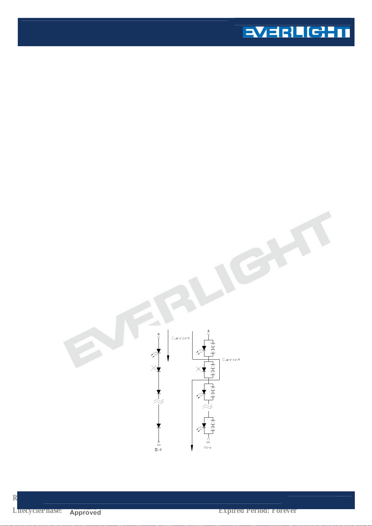
5. Circuit Protection
Below the zener reference voltage Vz, all the current flows through LED and as the voltage rises to Vz, the
zener diode “breakdown." If the voltage tries to rise above Vz current flows through the zener branch to keep
the voltage at exactly Vz.
When the LED is connected using serial circuit, if either piece of LED is no light up but current can’t flow through
causing others to light down. In new design, the LED is parallel with zener diode. if either piece of LED is no
light up but current can flow through causing others to light up.
9
Revision : 3
Copyright © 2010, Everlight All Rights Reserved. Release Date : Apr.25.2012. Issue No: DLE-0001736_Rev.3
LifecyclePhase:
Release Date:2012-04-26 13:21:29.0
www.everlight.com
Expired Period: Forever
Page 10
DATASHEET
LAMP
204-15UTC/S400-X9
6. Heat Management
Heat management of LEDs must be taken into consideration during the design stage of LED application. The
current should be de-rated appropriately by referring to the de-rating curve found in each product
specification.
The temperature surrounding the LED in the application should be controlled. Please refer to the data sheet
de-rating curve.
7. ESD (Electrostatic Discharge)
Electrostatic discharge (ESD) or surge current (EOS) can damage LEDs.
An ESD wrist strap, ESD shoe strap or antistatic gloves must be worn whenever handling LEDs.
All devices, equipment and machinery must be properly grounded.
Use ion blower to neutralize the static charge which might have built up on surface of the LEDs plastic lens as
a result of friction between LEDs during storage and handing.
8. Other
Above specification may be changed without notice. EVERLIGHT will reserve authority on material change for
above specification.
When using this product, please observe the absolute maximum ratings and the instructions for using outlined
in these specification sheets. EVERLIGHT assumes no responsibility for any damage resulting from use of
the product which does not comply
with the absolute maximum ratings and the instructions included in these specification sheets.
These specification sheets include materials protected under copyright of EVERLIGHT corporation. Please
don’t reproduce or cause anyone to reproduce them without EVERLIGHT’s consent.
10
Revision : 3
Copyright © 2010, Everlight All Rights Reserved. Release Date : Apr.25.2012. Issue No: DLE-0001736_Rev.3
LifecyclePhase:
Release Date:2012-04-26 13:21:29.0
www.everlight.com
Expired Period: Forever
 Loading...