

Page 1

EVERLIGHT ELECTRONICS CO.,LTD.
Technical Data Sheet
1206 Package Chip LED (1.1 mm Height)
15-21/G6C-FP1Q1L/2T
Features
․Package in 8mm tape on 7〞diameter reel.
․Compatible with automatic placement equipment.
․Compatible with infrared and vapor phase reflow
solder process.
․Mono-color type.
․Pb-free.
Descriptions
․The 15-21 SMD Taping is much smaller than lead frame
type components, thus enable smaller board
size, higher packing density, reduced
storage space and finally smaller equipment
to be obtained.
․Besides, lightweight makes them ideal for
miniature applications. etc.
Applications
․Automotive: backlighting in dashboard and switch.
․Telecommunication: indicator and backlighting in
telephone and fax.
․Flat backlight for LCD, switch and symbol.
․General use.
Device Selection Guide
Part No.
Material Emitted Color
15-21/G6C-FP1Q1L/2T AlGaInP Brilliant Yellow Green Water Clear
Chip
Lens Color
Everlight Electronics Co., Ltd. http://www.everlight.com Rev 1 Page: 1 of 10
Device No:SZDSE-151-G06 Prepared date:23-Mar-2005 Prepared by: Zhang huali
Page 2
EVERLIGHT ELECTRONICS CO.,LTD.
15-21/G6C-FP1Q1L/2T
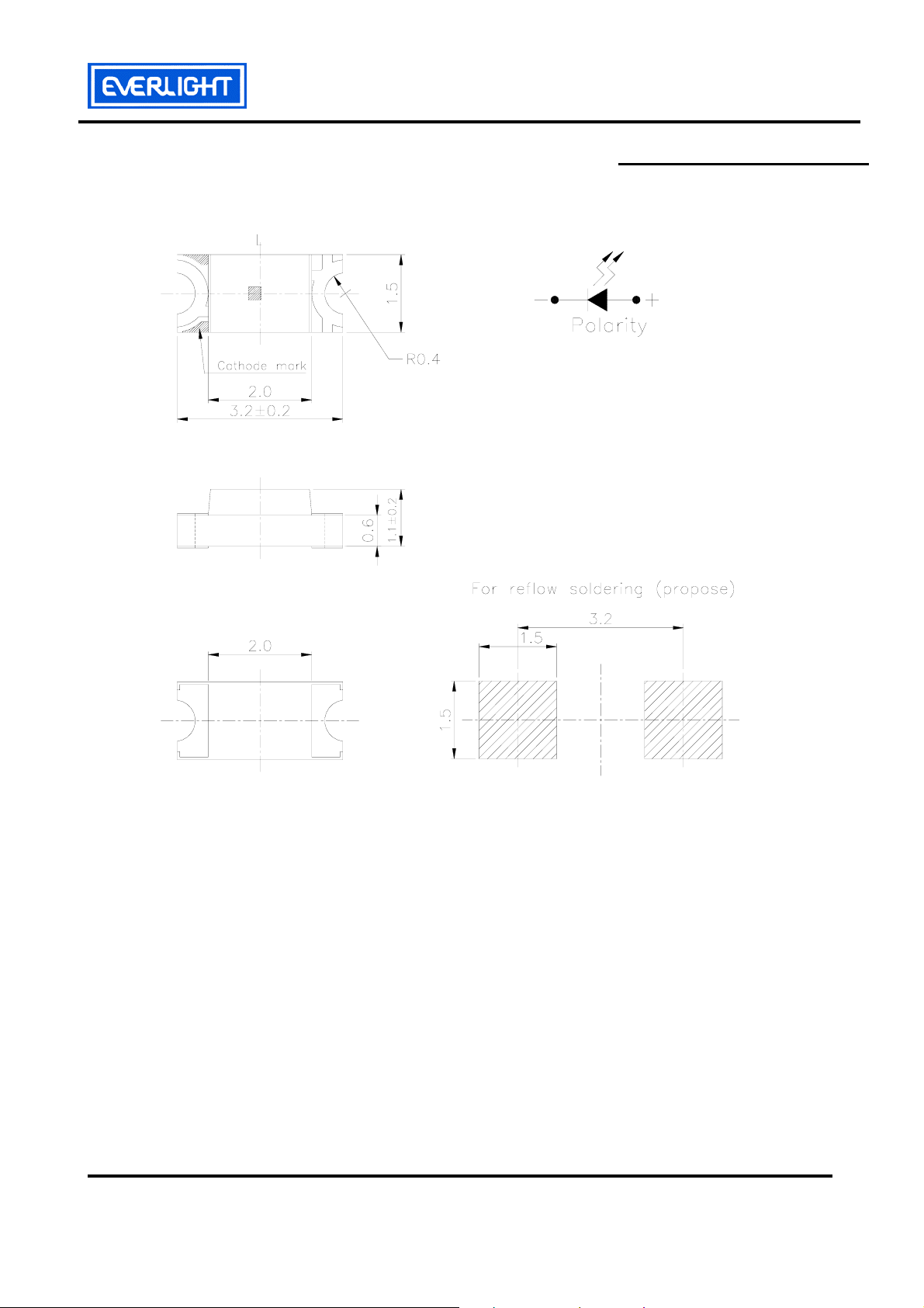
Package Outline Dimensions
Note: Tolerances Unless Dimension ±0.1mm , Unit = mm
Everlight Electronics Co., Ltd. http://www.everlight.com Rev 1 Page: 2 of 10
Device No:SZDSE-151-G06 Prepared date:23-Mar-2005 Prepared by: Zhang huali
Page 3

EVERLIGHT ELECTRONICS CO.,LTD.
15-21/G6C-FP1Q1L/2T
Absolute Maximum Ratings (Ta=25℃)
Parameter Symbol Rating Unit
Reverse Voltage V
Forward Current I
R
F
5 V
25 mA
Operating Temperature Topr -40 ~ +85 ℃
Storage Temperature Tstg -40 ~ +90 ℃
Electrostatic Discharge ESD 2000 V
Power Dissipation Pd 60 mW
Peak Forward Current
I
FP 60 mA
(Duty 1/10 @1KHz)
Reflow Soldering : 260℃ for 10sec.
Soldering Temperature Tsol
Hand Soldering : 350℃ for 3 sec.
Electro-Optical Characteristics (Ta=25℃)
Parameter Symbol Min. Typ. Max. Unit Condition
Luminous Intensity Iv 45.0 ----- 90.0 mcd
Viewing Angle 2θ1/2 ----- 140 ----- deg
Peak Wavelength λp ----- 575 ----- nm
I
=20mA
F
Dominant Wavelength
λd
570.0 ----- 574.5
nm
Spectrum Radiation
Bandwidth
△λ
Forward Voltage V
Reverse Current I
F 1.70 ----- 2.30
R
----- 20 -----
nm
V
----- ----- 10 μA
V
=5V
R
Notes:
1.Tolerance of Luminous Intensity ±10%
2.Tolerance of Dominant Wavelength ±1nm
3.Tolerance of Forward Voltage ±0.05V
Everlight Electronics Co., Ltd. http://www.everlight.com Rev 1 Page: 3 of 10
Device No:SZDSE-151-G06 Prepared date:23-Mar-2005 Prepared by: Zhang huali
Page 4
EVERLIGHT ELECTRONICS CO.,LTD.
15-21/G6C-FP1Q1L/2T
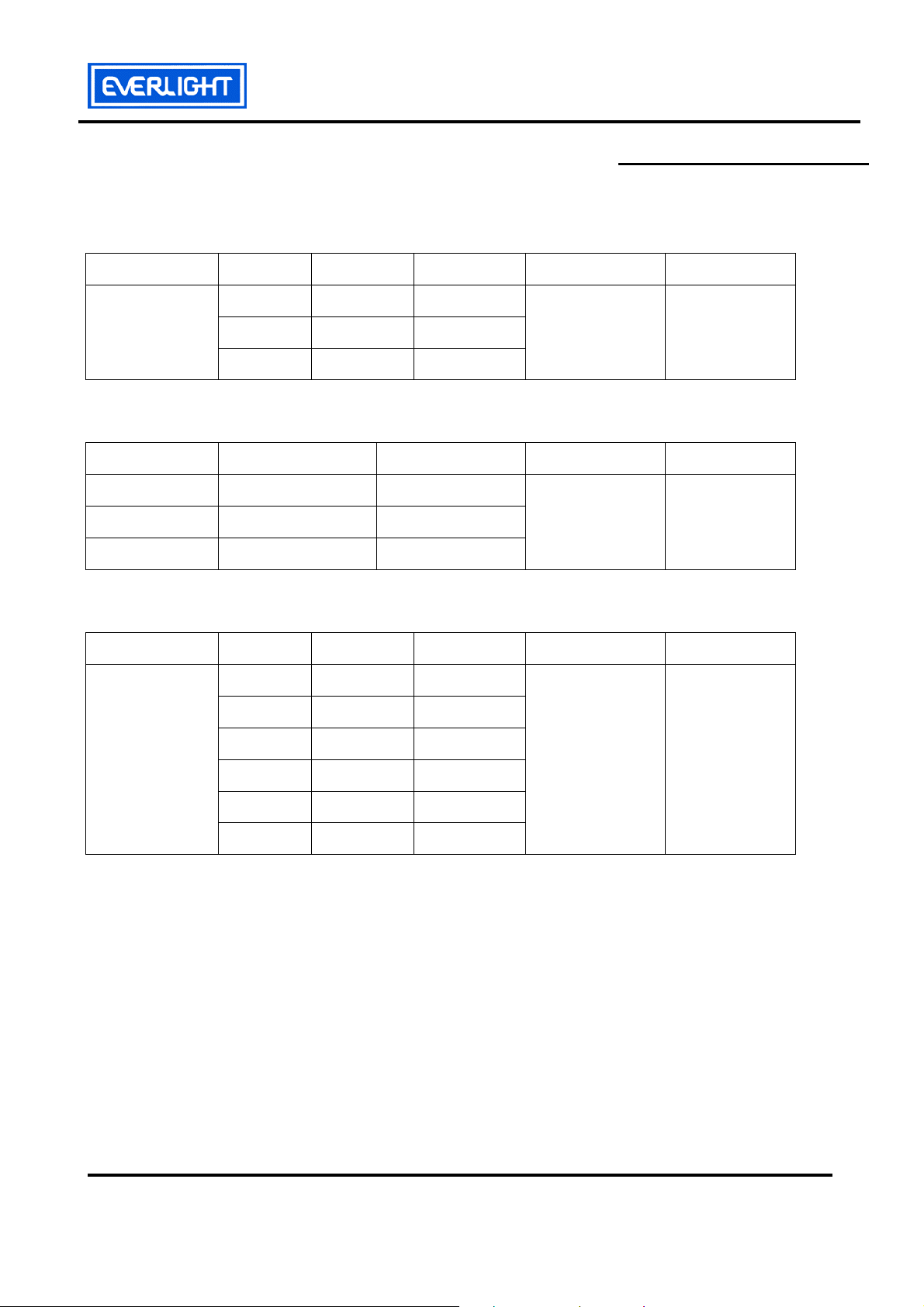
Bin Range Of Dom. Wavelength
Group Bin Min Max Unit Condition
CC2 570.0 571.5
F
CC3 571.5 573.0
CC4 573.0 574.5
nm IF=20mA
Bin Range Of Luminous Intensity
Bin Min Max Unit Condition
P1 45.0 57.0
P2 57.0 72.0
Q1 72.0 90.0
mcd I
Bin Range Of Forward Voltage
Group Bin Min Max Unit Condition
19
20
21
L
22
1.70 1.80
1.80 1.90
1.90 2.00
V IF=20mA
2.00 2.10
=20mA
F
23
24
2.10 2.20
2.20 2.30
Notes:
1.Tolerance of Luminous Intensity ±10%
2.Tolerance of Dominant Wavelength ±1nm
3.Tolerance of Forward Voltage ±0.05V
Everlight Electronics Co., Ltd. http://www.everlight.com Rev 1 Page: 4 of 10
Device No:SZDSE-151-G06 Prepared date:23-Mar-2005 Prepared by: Zhang huali
Page 5

EVERLIGHT ELECTRONICS CO.,LTD.
15-21/G6C-FP1Q1L/2T
Typical Electro-Optical Characteristics Curves
Everlight Electronics Co., Ltd. http://www.everlight.com Rev 1 Page: 5 of 10
Device No:SZDSE-151-G06 Prepared date:23-Mar-2005 Prepared by: Zhang huali
Page 6

EVERLIGHT ELECTRONICS CO.,LTD.
15-21/G6C-FP1Q1L/2T
Label explanation
CAT: Luminous Intensity Rank
HUE: Dom. Wavelength Rank
REF: Forward Voltage Rank
Reel Dimensions
Note: Tolerances Unless Dimension ±0.1mm , Unit = mm
Everlight Electronics Co., Ltd. http://www.everlight.com Rev 1 Page: 6 of 10
Device No:SZDSE-151-G06 Prepared date:23-Mar-2005 Prepared by: Zhang huali
Page 7

EVERLIGHT ELECTRONICS CO.,LTD.
15-21/G6C-FP1Q1L/2T
Carrier Tape Dimensions: Loaded quantity 2000 PCS per reel
Note: Tolerances Unless Dimension ±0.1mm , Unit = mm
Moisture Resistant Packaging
Label
Aluminum moisture-proof bag
Desiccant Label
Everlight Electronics Co., Ltd. http://www.everlight.com Rev 1 Page: 7 of 10
Device No:SZDSE-151-G06 Prepared date:23-Mar-2005 Prepared by: Zhang huali
Page 8

EVERLIGHT ELECTRONICS CO.,LTD.
15-21/G6C-FP1Q1L/2T
Reliability Test Items And Conditions
The reliability of products shall be satisfied with items listed below.
Confidence level:90%
LTPD:10%
No. Items Test Condition
Test
Hours/Cycles
Temp. : 260℃±5℃
1 Reflow Soldering
Min 5 sec.
6 Min.
H : +100℃ 15min
2 Temperature Cycle
∫ 5 min
300 Cycles
L : -40℃ 15min
H : +100℃ 5min
3 Thermal Shock
∫ 10 sec
300 Cycles
L : -10℃ 5min
4
High Temperature
Temp. : 100℃
1000 Hrs.
Storage
5
Low Temperature
Storage
6 DC Operating Life IF = 20 mA
Temp. : -40℃
1000 Hrs.
1000 Hrs.
Sample
Ac/Re
Size
22 Pcs. 0/1
22 PCS. 0/1
22 PCS. 0/1
22 PCS. 0/1
22 PCS. 0/1
22 PCS. 0/1
7
High Temperature /
85℃/85% RH
1000 Hrs.
22 PCS. 0/1
High Humidity
Everlight Electronics Co., Ltd. http://www.everlight.com Rev 1 Page: 8 of 10
Device No:SZDSE-151-G06 Prepared date:23-Mar-2005 Prepared by: Zhang huali
Page 9

EVERLIGHT ELECTRONICS CO.,LTD.
15-21/G6C-FP1Q1L/2T
Precautions For Use
1. Over-current-proof
Customer must apply resistors for protection , otherwise slight voltage shift will cause big
current change ( Burn out will happen ).
2. Storage
2.1 Do not open moisture proof bag before the products are ready to use.
2.2 Before opening the package, the LEDs should be kept at 30℃ or less and 90%RH or less.
2.3After opening the package, the LEDs should be kept at 30℃ or less and 70%RH or less(Floor life).
However,it’s recommended that The LEDs should be used within 168 hours (7 days) after opening
the package.If unused LED remain, it should be stored in moisture proof packages.
2.4 If the moisture absorbent material (silica gel) has faded away or the LEDs have exceeded the
storage time, baking treatment should be performed using the following conditions.
Baking treatment : 60±5℃ for 24 hours.
3. Soldering Condition
3.1 Pb-free solder temperature profile
3.2 Reflow soldering should not be done more than two times.
3.3 When soldering, do not put stress on the LEDs during heating.
3.4 After soldering, do not warp the circuit board.
4.Soldering Iron
Each terminal is to go to the tip of soldering iron temperature less than 350℃ for 3 seconds
within once in less than the soldering iron capacity 25W. Leave two seconds and more intervals, and do
soldering of each terminal. Be careful because the damage of the product is often started at the time of
the hand solder.
Everlight Electronics Co., Ltd. http://www.everlight.com Rev 1 Page: 9 of 10
Device No:SZDSE-151-G06 Prepared date:23-Mar-2005 Prepared by: Zhang huali
Page 10

EVERLIGHT ELECTRONICS CO.,LTD.
E
15-21/G6C-FP1Q1L/2T
5.Repairing
Repair should not be done after the LEDs have been soldered. When repairing is unavoidable, a
double-head soldering iron should be used (as below figure). It should be confirmed beforehand whether
the characteristics of the LEDs will or will not be damaged by repairing.
VERLIGHT ELECTRONICS CO., LTD. Tel: 0512-63409123-1603
Office: No 355,Zhong Shan North Rd ,WuJiang, Fax: 0512-63409123-1510
Economy Development Zone(YunXi Area), http://www.everlight.com
SongLing Town,WuJiang City,JiangSu PRC, China.
Everlight Electronics Co., Ltd. http://www.everlight.com Rev 1 Page: 10 of 10
Device No:SZDSE-151-G06 Prepared date:23-Mar-2005 Prepared by: Zhang huali
 Loading...