

EVERLIGHT ELECTRONICS CO.,LTD.
Technical Data Sheet
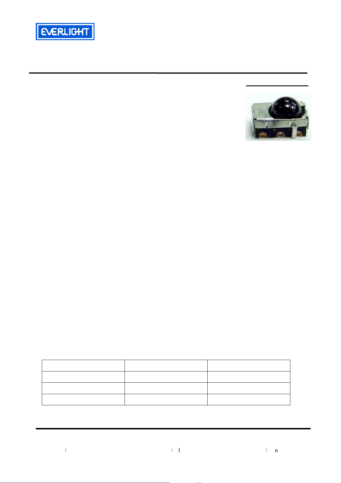
Infrared Remote-control Receiver Module
Features
‧High shielding against electric field disturbance.
‧Circular lens to improve the receive characteristic.
‧Line-up for various center carrier frequencies.
‧Low voltage and low power consumption.
‧High immunity against ambient light.
‧Photodiode with integrated circuit.
‧TTL and CMOS compatibility.
‧Top-received SMD.
‧Suitable burst length ≧
‧This product itself will remain within RoHS compliant version.
‧Pb free.
‧ External dimensions 5.3(L)*2.9(W)*3.65(H)mm.
10 pulses/burst.
Descriptions
The device is a miniature SMD type infrared remote
control system receiver that has been developed and
designed by utilizing the most updated IC technology. The
PIN diode and preamplifier are assembled on PCB, the
epoxy package is designed as an IR filter. The demodulated
output signal can directly be decoded by a microprocessor.
Applications
1. Light detecting portion of remote control
․AV instruments such as Audio, TV, VCR, CD, MD, etc.
․Home appliances such as Air-conditioner, Fan , etc.
․The other equipments with wireless remote control.
․CATV set top boxes
․Multi-media Equipment
Device Selection Guide
IRM-H538/TR2
PART MATERIAL COLOR
Chip Silicon ---
Package Epoxy Black
Metal case SPCC Silver white
Everlight Electronics Co., Ltd. http:\\www.everlight.com Rev 1 Page: 1 of 12
Device No
:
DMO-538-400 Prepared date:11-24-2006 Prepared by:Cindy Lin
EVERLIGHT ELECTRONICS CO.,LTD.
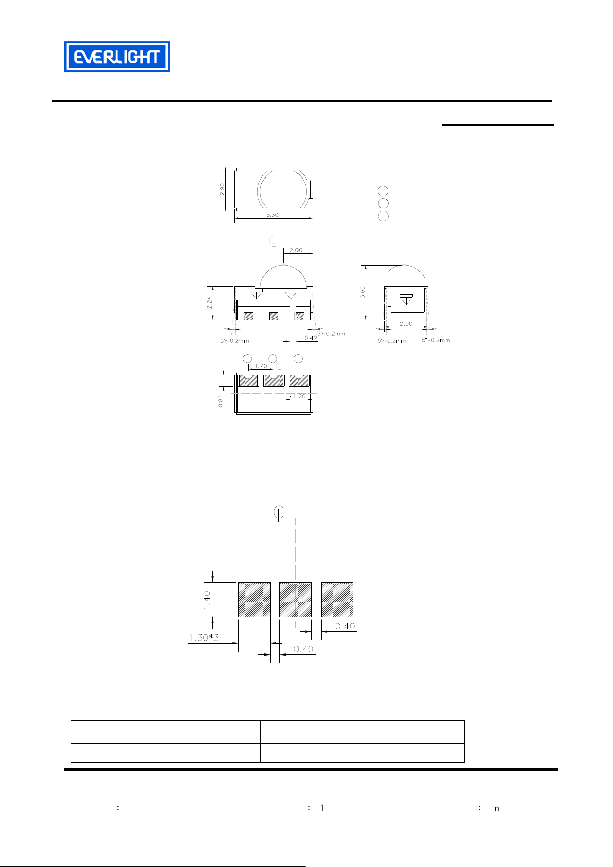
Package Dimensions
Notes::::1.All dimensions are in millimeters.
1
IRM-H538/TR2
Pin Function
1 :V
out
2 :V
cc
3 :GND
3
2
2.Tolerances unless dimensions ±0.2mm.
Soldering patterns
The following soldering patterns are recommended for reflow-soldering :
Unit: mm
Available Types For Different Carrier Frequencies
Type Carrier Frequencies (Typ)
IRM-H538/TR2 38 kHz
Everlight Electronics Co., Ltd. http:\\www.everlight.com Rev 1 Page: 2 of 12
Device No
:
DMO-538-400 Prepared date:11-24-2006 Prepared by:Cindy Lin
EVERLIGHT ELECTRONICS CO.,LTD.
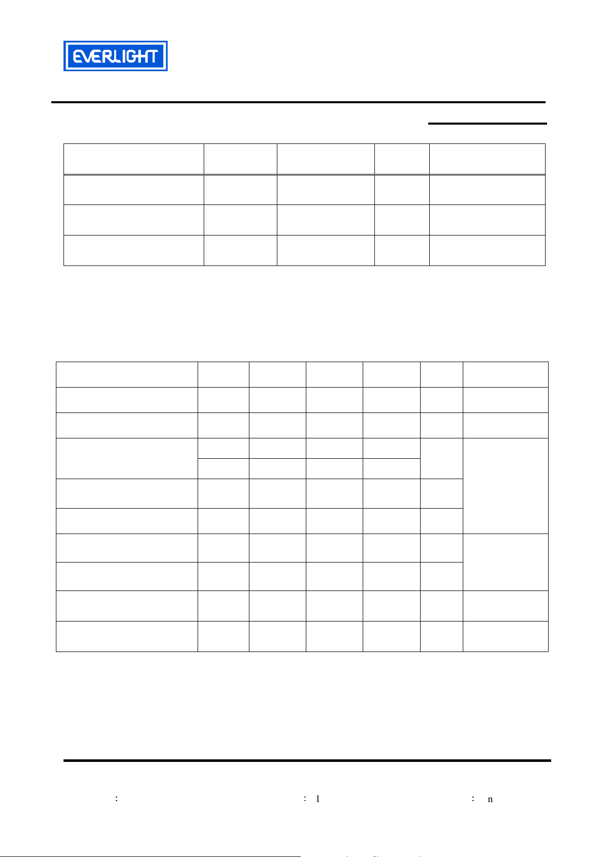
Absolute Maximum Ratings (Ta=25℃℃℃℃)
Parameter Symbol Rating Unit
Supply Voltage Vcc
Operating Temperature Topr
Storage Temperature Tstg
0~6
-25 ~ +85
-40 ~ +85
V
℃
℃
Recommended Operating Condition
Supply Voltage Rating: Vcc 2.7V to 5.5V
Electro-Optical Characteristics (Ta=25℃℃℃℃, and Vcc=3.0V)
Parameter Symbol
Supply Current Icc
MIN. TYP. MAX. Unit
--- --- 1.2
IRM-H538/TR2
Notice
Condition
mA No signal input
Peak Wavelength
Reception Distance
Half Angle(Horizontal)
Half Angle(Vertical)
High Level Pulse Width TH
Low Level Pulse Width TL
High Level Output Voltage
Low Level Output Voltage
Notes:
*1:The ray receiving surface at a vertex and relation to the ray axis in the range of θ= 0° and θ=45°.
*2:A range from 30cm to the arrival distance. Average value of 50 pulses.
λp
L0
L45
Θh
Θv
VH
VL
--- 940 ---
8 --- ---
5 --- ---
--- 45 ---
--- 45 ---
400 --- 800
400 --- 800
2.7 --- ---
--- 0.2 0.5
nm
m
deg
deg
μs
μs
V
V
At the ray axis
*1
At the ray axis
*2
Everlight Electronics Co., Ltd. http:\\www.everlight.com Rev 1 Page: 3 of 12
Device No
:
DMO-538-400 Prepared date:11-24-2006 Prepared by:Cindy Lin
EVERLIGHT ELECTRONICS CO.,LTD.
IRM-H538/TR2
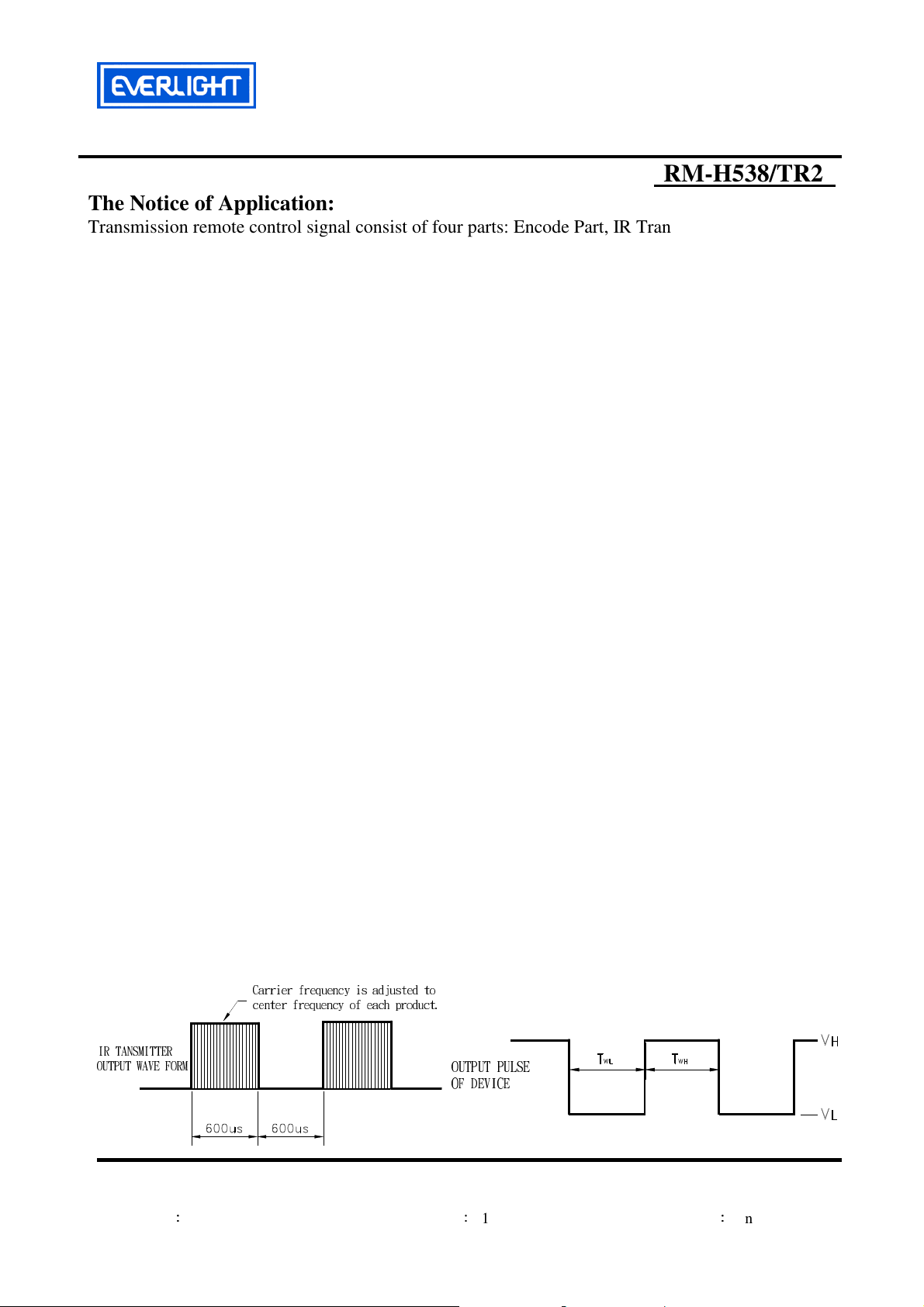
The Notice of Application:
Transmission remote control signal consist of four parts: Encode Part, IR Transmitter Source, IRM
device, Decode Part
1. When IRM-H538 code select frequency, it need to well understand the center system of
encode part.
2. Strong or weak light of IR Transmitter can affect distance of transmission.
3. Minimum Burst Length T
4. It needs to ensure the translation range of decode part if it is applied to the pulse-width range.
If the above items hardly assure of its application, it’ll cause NG(no good) message from the edge of
signal.
Test Method::::
The specified electro-optical characteristics is satisfied under the following
Conditions at the controllable distance.
Measurement place
A place that is nothing of extreme light reflected in the room.
External light
Project the light of ordinary white fluorescent lamps which are not high
Frequency lamps and must be less then 10 Lux at the module surface.
(Ee≦10Lux)
Standard transmitter
A transmitter whose output is so adjusted as to Vo=400mVp-p and the output
Wave form shown in Fig.-1.According to the measurement method shown in
Fig.-2 the standard transmitter is specified.
However , the infrared photodiode to be used for the transmitter should be
λp=940nm,∆λ=50nm. Also, photodiode is used of PD438B(Vr=5V).
(Standard light / Light source temperature 2856°K).
Measuring system
According to the measuring system shown in Fig.-3
Fig.-1 Transmitter Wave Form D.U.T output Pulse
IR TANSMITTER
OUTPUT WAVE FORM
Carrier frequency is adjusted to
center frequency of each product.
burst
(number of pulses per burst) : 10 cycles
OUTPUT PULSE
OF DEVICE
Duty=0.5
Everlight Electronics Co., Ltd. http:\\www.everlight.com Rev 1 Page: 4 of 12
Device No
:
DMO-538-400 Prepared date:11-24-2006 Prepared by:Cindy Lin

EVERLIGHT ELECTRONICS CO.,LTD.
IRM-H538/TR2
Fig.-2 Measuring Method Fig.-3 Measuring System
Standard Transmitter
Block Diagram:
20cm
10k
+5.0± 0.1V
10uF
k
0
0
1
Oscilloscope
Vout
Standard Transmitter
Vs
Input CGA & filter Demodulator
L: Transmission Distance
θ
θ
D.U.T
θ: Angle Of Horizontal & Vertical Direction
OUT
GND
OUT IN
Vcc
Vout
µC
Oscillator AGC/ATC & digital control
Carrier frequency f0
Modulated IR signal
min 10 pulses
GND
Application Circuit:
RC Filter should be connected closely between Vcc pin and GND pin.
Everlight Electronics Co., Ltd. http:\\www.everlight.com Rev 1 Page: 5 of 12
Device No
:
DMO-538-400 Prepared date:11-24-2006 Prepared by:Cindy Lin

EVERLIGHT ELECTRONICS CO.,LTD.
Typical Electro-Optical Characteristics Curves
Fig.-4 Relative Spectral Sensitivity vs.
Wavelength
Fig.-5 Relative Transmission Distance vs.
Direction
IRM-H538/TR2
θ
Fig.-6 Output Pulse Length vs. Arrival Distance Fig.-7 Arrival Distance vs. Supply Voltage
µ
10
8
6
4
2
Everlight Electronics Co., Ltd. http:\\www.everlight.com Rev 1 Page: 6 of 12
Device No
:
DMO-538-400 Prepared date:11-24-2006 Prepared by:Cindy Lin

EVERLIGHT ELECTRONICS CO.,LTD.
IRM-H538/TR2
Typical Electro-Optical Characteristics Curves
Fig.-8 Relative Transmission Distance
vs. Center Carrier Frequency
Fig.-9 Arrival Distance vs. Ambient Temperature
8
6
4
Everlight Electronics Co., Ltd. http:\\www.everlight.com Rev 1 Page: 7 of 12
Device No
:
DMO-538-400 Prepared date:11-24-2006 Prepared by:Cindy Lin

EVERLIGHT ELECTRONICS CO.,LTD.
1000hrs
IRM-H538/TR2
Reliability Test Item And Condition
The reliability of products shall be satisfied with items listed below.
Confidence level:90%
LTPD:10%
Reflow Terms: JEDEC Level 4 Specification
Drying; Temp.:125℃ 24hrs Moisture 30℃ / 60% RH 96hrs Reflow Temp.: 260℃±5℃
10sec, 3 times
Note:
1. Not sooner than 15 minutes and not longer than 4 hours after removal from the
temperature/humidity chamber.
2. The time between reflow shall be 5 minutes minimum and 60 minutes maximum.
Test Items Test Conditions
Failure Judgement
Criteria
Samples(n)
Defective(c)
Temperature cycle
High temperature test
Low temperature
storage
High temperature
High humidity
1 cycle:-25℃ +85℃
(30min)(5min)(30min)
300 cycle test
Temp:+85℃
Vcc:5V
Temp:-40℃
1000hrs
Ta:85℃,RH:85%
1000hrs
L0≦ L×0.8
L45≦ L×0.8
L: Lower
specification limit
*Icc : Operate
Current (mA)
Variation≦±20%:
n=76,c=0
n=76,c=0
n=76,c=0
n=76,c=0
Everlight Electronics Co., Ltd. http:\\www.everlight.com Rev 1 Page: 8 of 12
Device No
:
DMO-538-400 Prepared date:11-24-2006 Prepared by:Cindy Lin

EVERLIGHT ELECTRONICS CO.,LTD.
IRM-H538/TR2
Recommended method of storage
Dry box storage is recommended as soon as the aluminum bag has been opened prevent
moisture absorption. The following conditions should be observed, if dry boxes are not available:
Storage temperature 10℃ to 30℃
Storage humidity ≦60%RH max.
After more than 72 hours under these conditions moisture content will be too high for
Reflow soldering:
In case of moisture absorption, the devices will recover to former condition by drying
under the following condition:
192 hours at 40℃+5℃/-0℃ and 5%RH (dry air / nitrogen) or
96 hours at 60℃+5℃ and < 5%RH for all device containers or
24 hours at 125℃+5℃ not suitable for reel or tubes.
ESD Precaution
Proper storage and handing procedures should be followed to prevent ESD damage to
the devices especially when they are removed from the Anti-static bag. Electro-Static Sensitive
Devices warning labels are on the packing.
Recommended Solder Profile
1~5°C/sec
60sec. Max.
Above. 220°C
1~5°C/sec.
Pre-heating
180~200°C
120sec.Max.
Notice:
(1) Reflow soldering should not be done more than two times.
(2) When soldering, do not put stress on the IRM-H538/TR1 Series devices during heating.
(3) After soldering, do not warp the circuit board.
260°C Max.
10sec Max.
Everlight Electronics Co., Ltd. http:\\www.everlight.com Rev 1 Page: 9 of 12
Device No
:
DMO-538-400 Prepared date:11-24-2006 Prepared by:Cindy Lin

EVERLIGHT ELECTRONICS CO.,LTD.
IRM-H538/TR2
Soldering Iron
seconds within once in less than the soldering iron capacity 25W. Leave two seconds and more
intervals, and do soldering of each terminal. Be careful because the damage of the product is often
started at the time of the hand solder.
Repairing
Repair should not be done after the Devices have been soldered. When repairing is
unavoidable, a double-head soldering iron should be used (as below figure). It should be confirmed
beforehand whether the characteristics of the Devices will or will not be damaged by repairing.
Each terminal is to go to the tip of soldering iron temperature less than 350℃ for 3
Everlight Electronics Co., Ltd. http:\\www.everlight.com Rev 1 Page: 10 of 12
Device No
:
DMO-538-400 Prepared date:11-24-2006 Prepared by:Cindy Lin

EVERLIGHT ELECTRONICS CO.,LTD.
IRM-H538/TR2
Packing Quantity Specification
1. 2000 PCS/1 Reel
2. 5 Reel /1Carton
Carrier Tape Dimensions: Loaded quantity 2000 PCS per reel
Progressive Direction
Cover Trap
Packing process
Bar Code Label
Everlight Electronics Co., Ltd. http:\\www.everlight.com Rev 1 Page: 11 of 12
Device No
:
DMO-538-400 Prepared date:11-24-2006 Prepared by:Cindy Lin

EVERLIGHT ELECTRONICS CO.,LTD.
IRM-H538/TR2
Label Form Specification
CPN: Customer’s Production Number
P/N : Production Number
QTY: Packing Quantity
CAT: None
HUE: None
REF: Reference
LOT No: Lot Number
MADE IN TAIWAN: Production Place
Notes
1. Above specification may be changed without notice. EVERLIGHT will reserve authority on
material change for above specification.
2. When using this product, please observe the absolute maximum ratings and the instructions
for using outlined in these specification sheets. EVERLIGHT assumes no responsibility for
any damage resulting from use of the product which does not comply with the absolute
maximum ratings and the instructions included in these specification sheets.
3. These specification sheets include materials protected under copyright of EVERLIGHT
corporation. Please don’t reproduce or cause anyone to reproduce them without
EVERLIGHT’s consent.
EVERLIGHT ELECTRONICS CO., LTD. Tel: 886-2-2267-2000, 2267-9936
Office: No 25, Lane 76, Sec 3, Chung Yang Rd, Fax: 886-2267-6244, 2267-6189, 2267-6306
Tucheng, Taipei 236, Taiwan, R.O.C http:\\www.everlight.com
Everlight Electronics Co., Ltd. http:\\www.everlight.com Rev 1 Page: 12 of 12
Device No
:
DMO-538-400 Prepared date:11-24-2006 Prepared by:Cindy Lin
 Loading...