

Page 1

IP PBX Installation guide
MUC1004/2008/2016
IP PBX
Installation guide
Version V1.0
Date: 20th July, 2016
1 / 20
Page 2

IP PBX Installation guide
2 / 20
Page 3

IP PBX Installation guide
Table of Contents
1.
Preparation before installation .............. 4
2.
Hardware specifications ........................ 4
2.1 overview ................................................................................................ 4
2.2 Specifications and Operating Environment ................................................ 8
3.
MUC Series IP-PBX Installation ............. 8
3.1 Placement Instructions ......................................................................... 8
3.2 Installation Instructions ........................................................................ 8
3.2.1 Connection of Ethernet Ports ...................................................... 9
3.2.2 Connection of FXO/GSM/UMTS/BRI Ports ..................................... 9
3.2.3 Connection of FXS Ports ........................................................... 11
3.2.4 Power Connection .................................................................... 12
3.2.5 Overall Flow Chart ................................................................... 12
4.
MUC series Basic Configurations ......... 15
4.1 Factory Defaults ................................................................................... 15
4.2 Web Interface Configuration .................................................................. 15
4.3 Network Settings .................................................................................. 17
4.4 Reset to Factory Defaults ...................................................................... 19
5.
Conclusion ............................................ 19
3 / 20
Page 4
Input of 100
-
240V AC
power, Output
For wireless module (
optional, according
IP PBX Installation guide
1. Preparation before installation
Please make sure the following devices are available before
installation:
Contents of box
Upon receiving MUC series PBX gift box, please open the package and check if all the
items are supplied as Packing List (see Table1-1).If there is any problem, please
contact your provider.
Item Unit QTY Description
MUC1004/2008/2016 PC 1 MUC1004/2008/2016 main box
AC adapter PC 1
DC12V/1A(Only for MUC1004);
Input of 100-240V AC power, Output
DC12V/3A(for MUC2008/2016);
Power cord PC 1 For the input of 100-240V AC power(only
for MUC2008/2016)
Phone line PC 2
Network cable PC 1
Antenna
to the number of GSM/UMTS module)
Table1-1 Packing List
2. Hardware specifications
2.1 overview
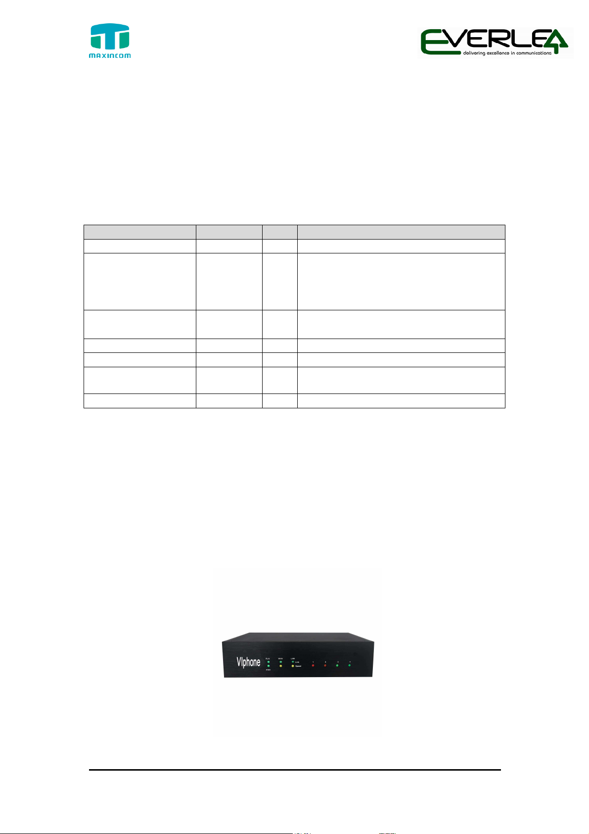
Figure 2-1 Front view of MUC1004
4 / 20
Page 5
On: Starting
IP PBX Installation guide
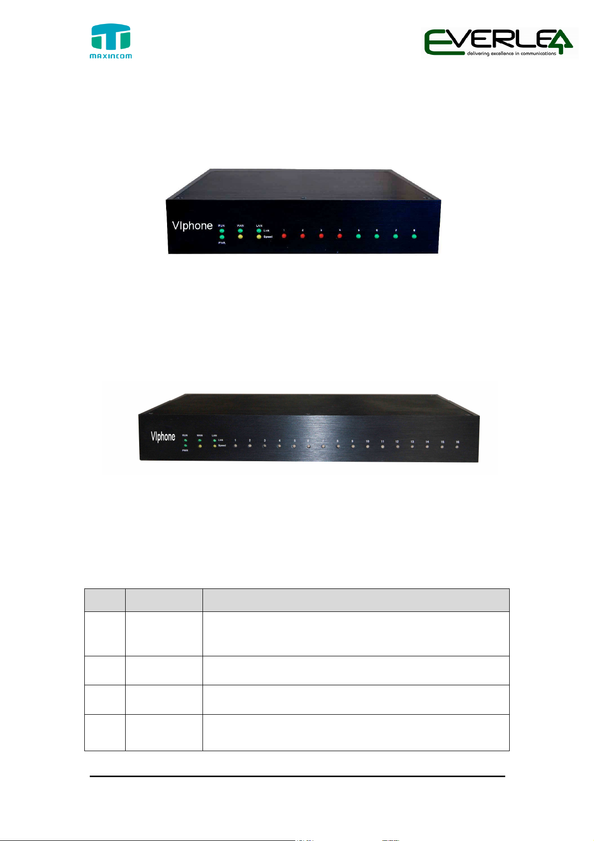
Figure 2-2 Front view of MUC2008
Figure 2-3 Front view of MUC2016
Table 2-1 Description of Front view
Index Indicators Description
1 RUN
Off: Abnormal
Blinking every 0.5s: Normal status
2 PWR
3 WAN,LAN
4
5 / 20
1~4,(5~8),
(9~16)
On: Power on
Off: Power off
Green LED: indicates the Internet interface is in Link.
Yellow LED: ON is indicates 100MBps Ethernet port.
Red LED stands for FXO port
Orange LED indicates presence of a BRI port.
Page 6
IP PBX Installation guide
Green LED stands for FXS port
Red LED blinks: FXO port isn’t connected to PSTN line.
Alternately blinks Red and Green: FXO port has an
incoming call.
Alternately blinks Red and Green fast: FXO port is in a
call.
Alternately blinks Green and Red: FXS port is ringing.
Alternately blinks Green and Red fast: FXS port is in a
call.
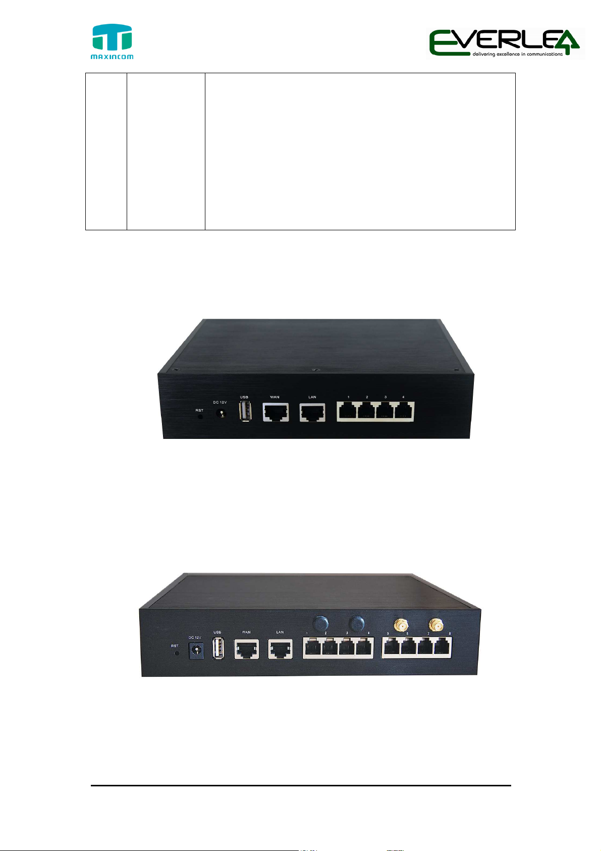
Figure 2-4 Rear view of MUC1004
Figure 2-5 Rear view of MUC2008
6 / 20
Page 7
USB
For the storage of call recording files
IP PBX Installation guide
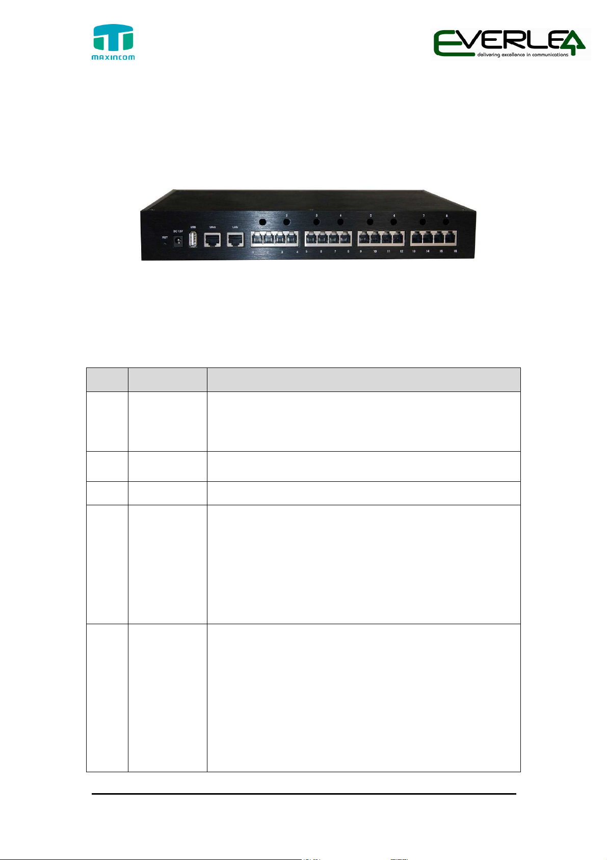
Figure 2-6 Rear view of MUC2016
Table 2-2 Description of Rear view
Index Interface Description
Reset button to restore default IP and password or
1 RST
restore factory setting.
Hold RST button 8 seconds, RUN LED being ON during
this time
2
DC 12V Power connector of DC power. Input: DC12V 3A/DC12
1A(MUC1004 only)
3
4
WAN,LAN
MUC2008 provides two 10/100 adaptive RJ45 Ethernet
ports, marked as LAN and WAN.
-LAN port :LAN port is for the connection to Local Area
Network
-WAN port: WAN port is the network port for the
connection to internet. It supports “DHCP
server”,”PPPoE/dynamic DNS”, and “static IP”for IP
address assignment.
5
1~4,(5~8),
(9~16)
FXO port (red light): For the connection of PSTN lines
or FXS port of traditional PBX.MU2008 users could make
or receive calls via FXO port.
FXS port (green light): For the connection of analog
phones.
BRI port (orange port): For the connection of ISDN BRI
lines. MU2008 users could make or receive calls via BRI
port.
Note: The sequence number of the port corresponds to
that of the indicator lights in the front panel.
7 / 20
Page 8

185*152*45mm(MUC1004);220*197*45mm(
MUC2008);
323*197*45mm(MUC2016)
Power supply
MUC1004: AC100~240V,50/60Hz Input, DC 12V/1A Output
0~50
℃
-
20~80
℃
Operation
IP PBX Installation guide
2.2 Specifications and Operating Environment
Description
Size
MUC2008/2016: AC100~240V,50/60Hz Input, DC 12V/3.3A
Output
Operation
Storage
10%~90%
3. MUC Series IP-PBX Installation
To avoid unexpected accident,personal injury or device damage,please read the
following instruction before installing the device.
3.1 Placement Instructions
Ambient temperature: to avoid overheating, please do not run the device in
the place where the ambient temperature is above 50℃.
Ventilation: please make sure that the device has good ventilation
around
Anti-jamming: there may be some sources of interference that might affect
the normal running of MUC series device. It is highly recommend that the
device:
Should be placed away from high-power radio, radar transmitters and
high frequency, and high-current devices.
Is using independent power junction box and effective anti-grid
interference measures have been taken.
Mechanical load: Please make sure that the device is placed steadily to
avoid any accident that might cause damage. If places on the desktop,
Please ensure it is horizontally placed.
3.2 Installation Instructions
After placing the device in a suitable place, please connect the power adapter
and all other cables following the instructions below.
8 / 20
Page 9
IP PBX Installation guide
We use the MUC2008 device as an installation case as follows:
3.2.1 Connection of Ethernet Ports
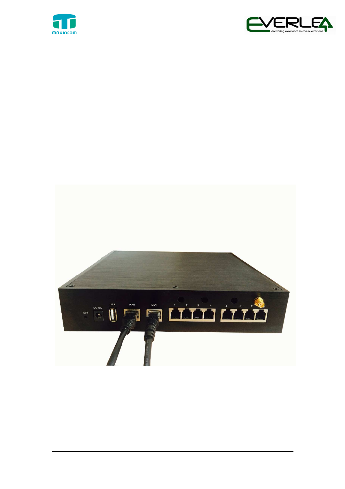
All the MUC series IP-PBX provide two standard 10/100M adaptive RJ45 Ethernet port,
LAN port and WAN port.
WAN Port Connection
Connection one end of the network cable to the WAN port of MUC series device,
and the other end to Ethernet port of a hub, switch or ADSL modem.
LAN Port Connection
Connection one end of the network cable to the LAN port of MUC series device,
and the other end to any port of LAN switch/router.
NOTE: if the LAN port is connected to a PC directly, please use cross-over
cable.
Figure 3-1 Network cable connection
3.2.2 Connection of FXO/GSM/UMTS/BRI Ports
The MUC series device support various outside lines (FXO, GSM, UMTS, and BRI).
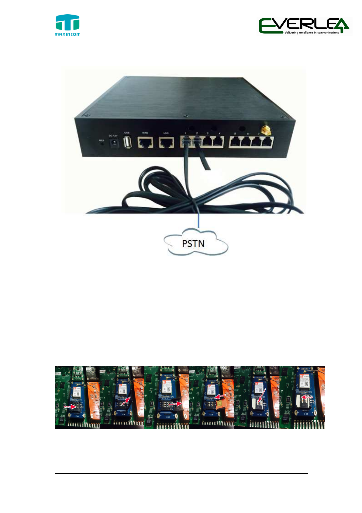
1. connection of FXO ports
The FXO port could be connected to the PSTN line or the FXS port of a traditional PBX
with a phone line.
9 / 20
Page 10
IP PBX Installation guide
For instance, if the port 1 and port 2 are FXO port, the connection could be like as
below:
Figure 3-2 PSTN connection
The other end of phone line connects to PSTN line or a FXS of traditional PBX.
2. Connection of GSM/UMTS port
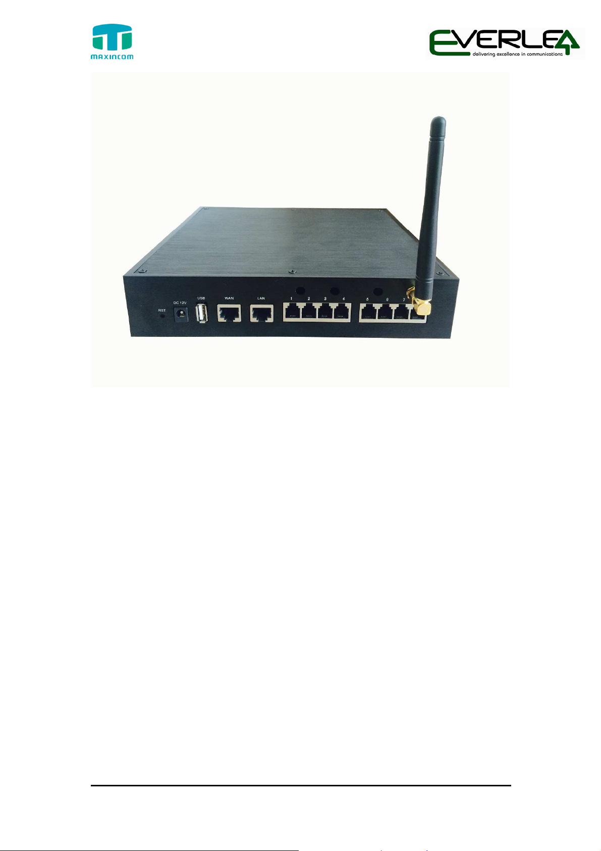
If port7 and port8 are GSM/UMTS ports, the steps of connection are as below:
Step1: Open the Upper case of MU2008
Step2: Insert the SIM card:
Figure 3-3 Inserting the SIM Card
Step3: Connect the antenna
10 / 20
Page 11
IP PBX Installation guide
Figure 3-4 Install the Antenna
3. Connection of BRI port
The BRI port could be connected to the BRI line or the BRI port of a traditional PBX
with a BRI RJ45-RJ11 cable.
3.2.3 Connection of FXS Ports
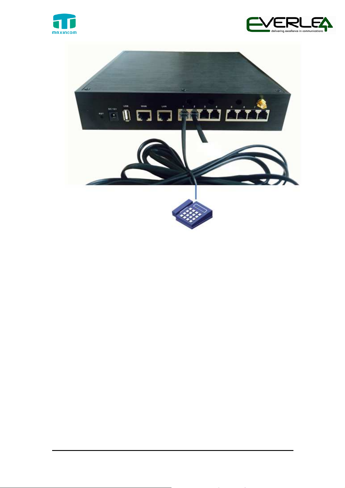
The FXS port could be connected to an analog phone or a fax with a phone line.
For instance, if the port 1 and port 2 are FXS port, the connection could be like as
below:
11 / 20
Page 12
IP PBX Installation guide
Figure 3-5 FXS Connection
The other end of the phone line connects to an analog phone.
3.2.4 Power Connection
After make sure the device has installed completed, connect the power cord.
The MUC series adapt 12VDC Power adapter, make sure AC power supply
grounded well to ensure the reliability and stability.
Notes: incorrect power connection may damage power adapter and device.
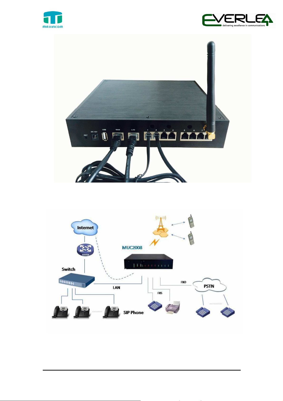
3.2.5 Overall Flow Chart
12 / 20
Page 13
IP PBX Installation guide
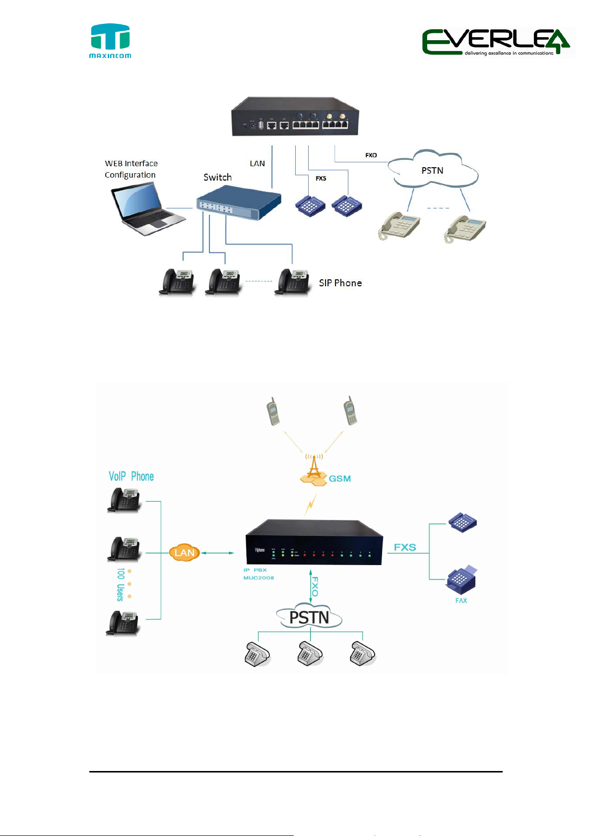
There are some typical application of the MUC series IP-PBX.
Figure 3-5 Overall Flow chat
Figure 3-6 Application1
13 / 20
Page 14
IP PBX Installation guide
Figure 3-7 Application2
Also, the MUC series can cooperate with the MWG series (VOIP GSM/UMTS
Gateway) for more flexible and powerful wireless application.
Figure 3-8 Application3
14 / 20
Page 15

IP PBX Installation guide
4. MUC series Basic Configurations
4.1 Factory Defaults
The MUC series device provide web-based configuration interface for administrator
and account user. The administrator can manage the device by log in the web
interface.
The factory default IP address:
LAN: 192.168.6.200
Access path:http://[IP address]
User name: admin
Password: password
Default SIP UDP port: 5060
There are 6 extensions set up by default. The extension numbers are
“100”-“105”and the password is generated randomly.
4.2 Web Interface Configuration
The MUC series PBX contains an embedded web server to set parameters by
using the HTTP protocol. We are strongly recommend to access device with
Google Chrome or Firefox Browser. Enter IP address of MUC2008 in IE/Google
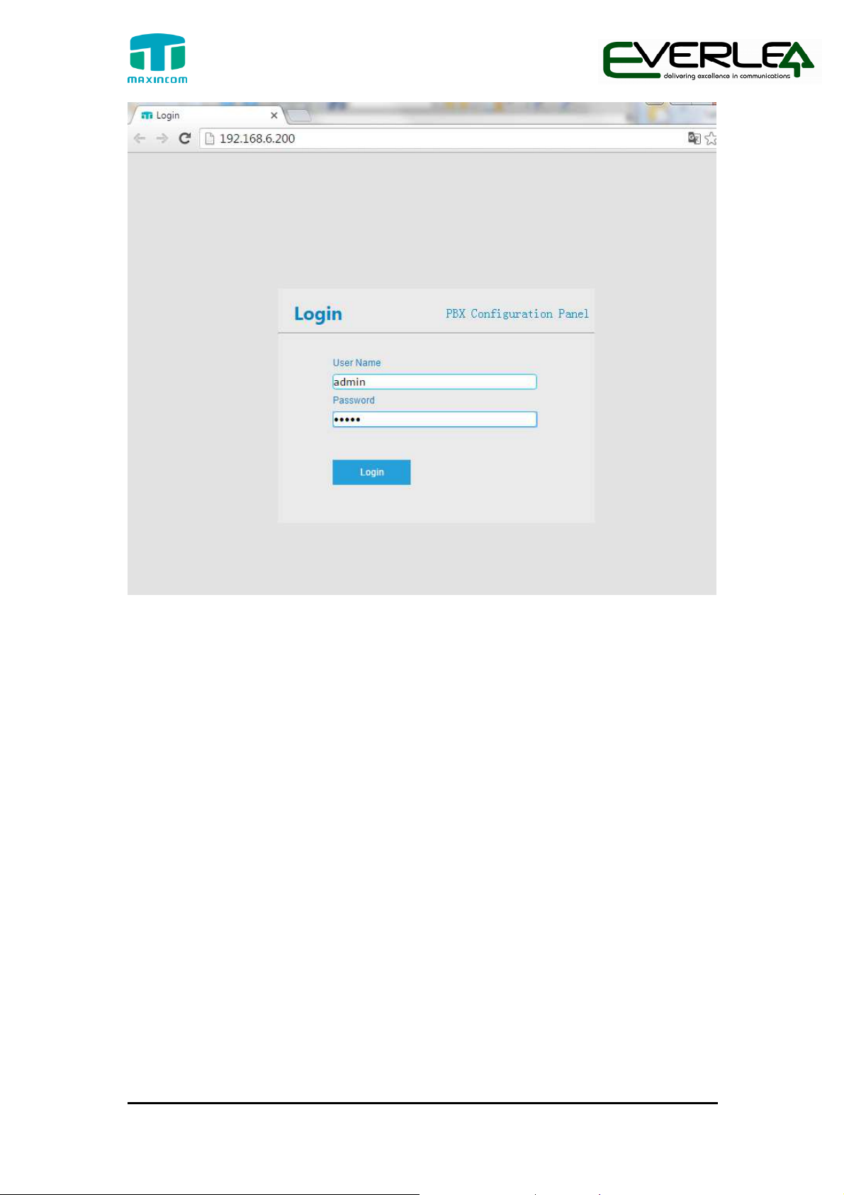
Chrome/Firefox Browser. The default IP of LAN port is 192.168.6.200. Enter
username and password and then click “Login” in configuration interface. The
default username and password are “admin/admin” and the GUI shows as
below:
15 / 20
Page 16
IP PBX Installation guide
Figure 4-1
NOTE: please check if the IP address that assigned to the network port (LAN or WAN) is in the
same segment with the PC’s IP address.
Web login interface
Via the web configuration interface, the admin can set all the system
configuration, including Network Configuration、Trunks、PBX Basic、PBX inbound
call control、PBX Advanced settings、Voice Management、System Preferences、
Phone Provisioning、Reports and System Tools.
Go through navigation tree, user can check, view, modify, and set the device
configuration on the right of configuration interface.
16 / 20
Page 17
IP PBX Installation guide
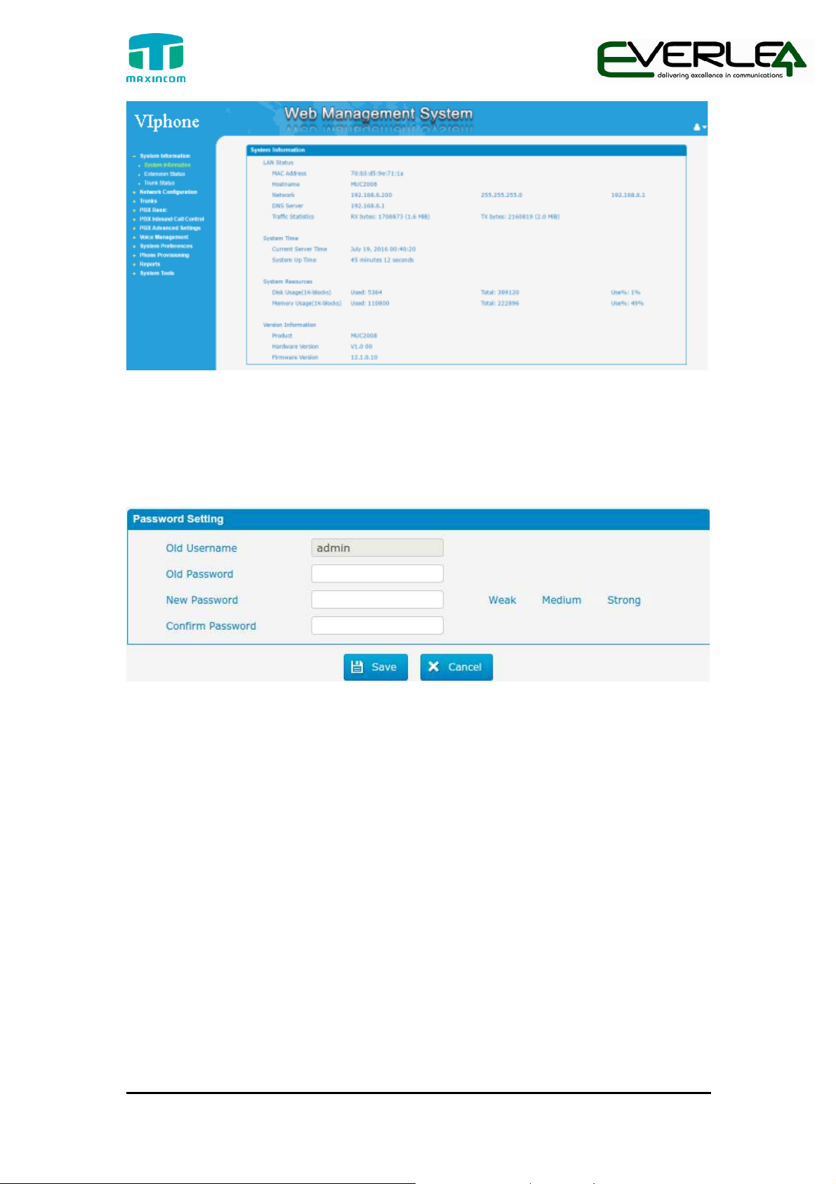
Figure 4-2
Web Management System
It is strongly recommended, change the default password to a new password
for system security .Click “System Preferences”->”Password” on the web.
Figure 4-3
4.3 Network Settings
After logging in the web configuration interface, generally the first step is to configure
the IP address. We also suggest the user to change the IP of LAN port. If the WAN port
is connected to the Internet, its IP address need to be configured.
Password Setting
WAN settings
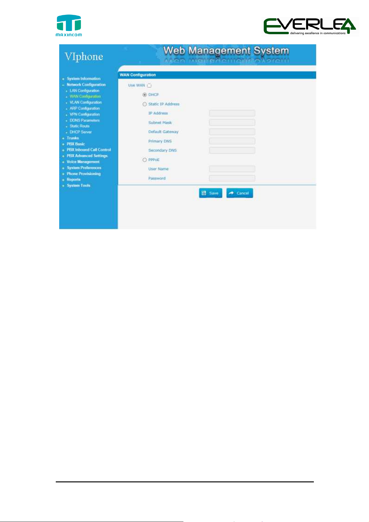
Click “Network Configuration”->”WAN Configuration” on the navigation tree.
There are three options to configuration, DHCP 、Static IP Address or PPPoE,
user can choose any one according to practical situation. For instance, use can
Choose”DHCP”, show as below:
17 / 20
Page 18
IP PBX Installation guide
Figure 4-4
WAN Setting
LAN settings
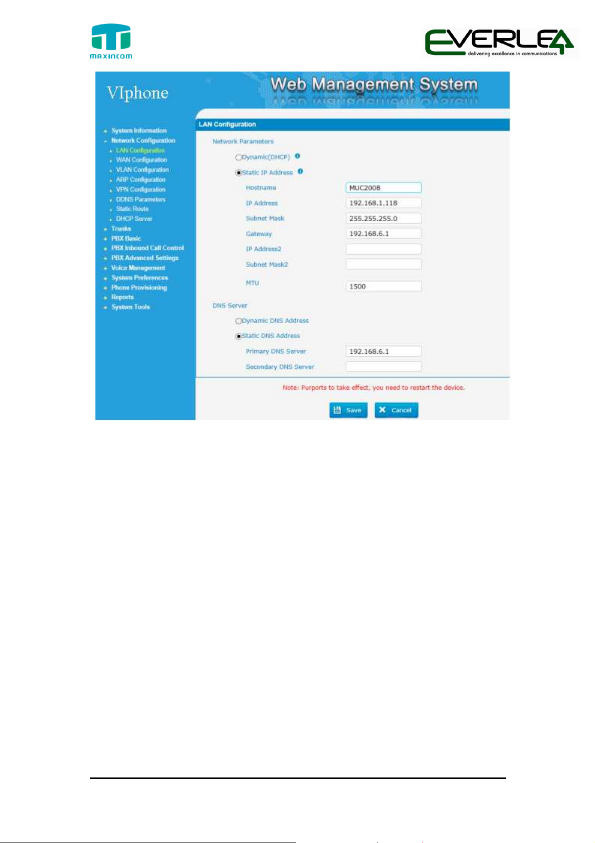
Click “Network Configuration”->”LAN Configuration” on the navigation tree.
LAN port is used for the interoperability of MUC2008.If LAN port is connected
to the company’s LAN, please configure the correct IP address and
corresponding subnet mask.
For instance, we choose the “static IP Address” and change the IP to
“192.168.1.118”
18 / 20
Page 19
IP PBX Installation guide
Figure 4-5 LAN
Note: After setting the IP address of LAN port or WAN port, you need to
Click “Save “and reboot the device to make the new setting taking effect.
4.4 Reset to Factory Defaults
If you forget the new IP address or the password of admin, or in other case you
want to restore the factory defaults. Please press the ”RST” button located in
the back panel with and hold 8 seconds with a paper clip or a pencil tip.
Setting
5. Conclusion
This Installation Guide only explains the installation and basic setting, for more detail
about functionality and setting, please refer to the relative documents as below:
“MUC1004_Datasheet_V1.0”
“MUC1004 Administrator_guide_V1.0”
“MUC2008_Datasheet_V1.0”
“MUC2008 Administrator_guide_V1.0”
19 / 20
Page 20

IP PBX Installation guide
“MUC2016_Datasheet_V1.0”
“MUC2016 Administrator_guide_V1.0”
20 / 20
 Loading...