

Page 1

ABBATTITORI / SURGELATORI RAPIDI
BLAST CHILLERS / SHOCK FREEZERS
PROFESSIONAL
TRAY
Manuale d’uso e manutenzione
Use and maintenance manual
Rev.3 10/2016
Page 2
1
ITALIANO
Grazie per aver scelto questo prodotto.
Leggere attentamente le avvertenze contenute nel presente manuale in quanto forniscono importanti
indicazioni riguardanti la sicurezza, d’uso e di manutenzione.
Conservare con cura questo manuale per ogni ulteriore consultazione dei vari operatori.
In alcune parti del manuale è presente il simbolo
indicante una avvertenza importante da
rispettare ai fini della sicurezza.
CAPITOLO 1 CARATTERISTICHE LIMITE DI FUNZIONAMENTO
L’abbattitore di temperatura è stato progettato e realizzato per poter funzionare in condizioni ottimali
in ambienti con temperature fino a +43°C, con adeguato ricircolo d’aria. In luoghi con caratteristiche
diverse da quelle previste non sarà possibile garantire le prestazioni dichiarate.
La tensione di alimentazione di serie mod. PROF ABF 05 230V/50Hz ,
mod.PROF ABF 10-15-20 400V/3N-Ph/50Hz oppure quella indicata sull’etichetta CE
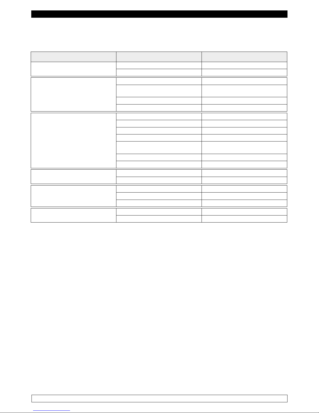
La seguente tabella riporta le capacità in Kg. di raffreddamento e/o surgelamento.
Modello Raffreddamento rapido +90°C / +3°C Surgelamento rapido +90°C / -18°C
PROF ABF 05 22 Kg. 14 Kg.
PROF ABF 10 35 Kg. 25 Kg.
PROF ABF 15 55 Kg. 35 Kg.
PROF ABF 20 75 Kg. 55 Kg.
N.B.: i tempi e le quantità in Kg. sopra indicati sono validi per prodotti con spessore massimo di 4 cm.
Tempo massimo: Raffreddamento positivo entro 90 min, Surgelazione entro 240 min
L’abbattitore di temperatura è conforme alle direttive Europee come riportato in dettaglio nell’allegato
“Dichiarazione CE di conformità”
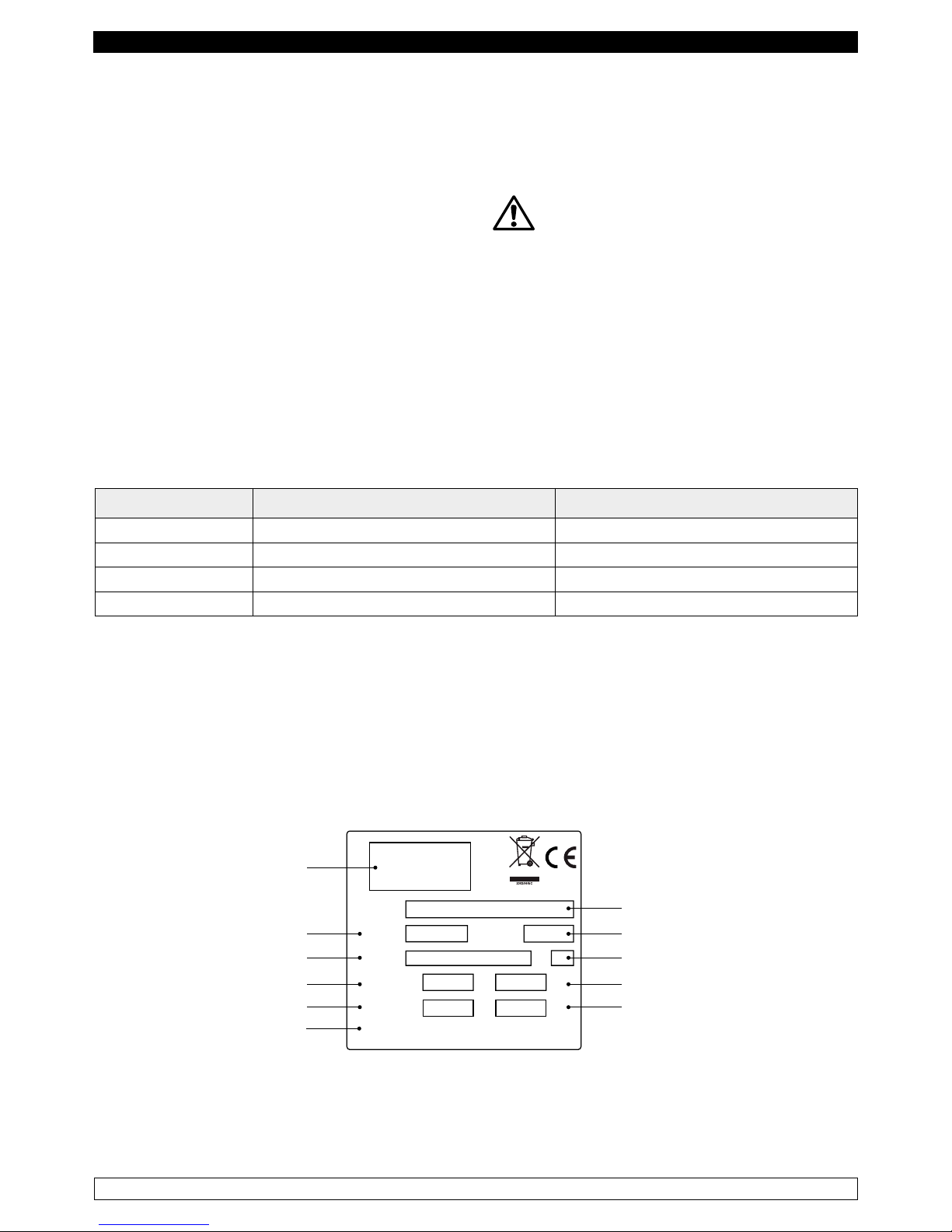
I dati sono riportati sull’etichetta CE posta nell’abbattitore di temperatura, all’interno del vano
motore.
A
Kw
Kg
CL.
Matricola
Ser. Number
Modello
Model
Cod.Art
Code
Tensione
Tension
Assorbimento
Absorption
Gas
Gaz
IP20, CLASS 1
Modello
Matricola
Classe climatica
Potenza elettrica
Quantità di uido refrigerante
Azienda costruttrice
Codice articolo
Tensione di alimentazione
Assorbimento elettrico
Tipo di uido refrigerante
Grado di protezione
Il fabbricante declina qualsiasi responsabilità per gli usi impropri e non ragionevolmente previsti
dell’abbattitore di temperatura e per tutte quelle operazioni effettuate sullo stesso trascurando le
indicazioni riportate sul manuale.
Page 3
2
ITALIANO
Di seguito sono elencate le principali norme di sicurezza generali :
- Non utilizzare o inserire apparecchi elettrici all’interno dei comparti refrigerati se non del tipo
consigliato dal produttore
- Non toccare l’abbattitore di temperatura avendo mani o piedi umidi o bagnati
- Non usare l’abbattitore di temperatura a piedi nudi
- Non inserire cacciaviti od altro tra le protezioni o le parti in movimento
- Non tirare il cavo di alimentazione per scollegare l’abbattitore di temperatura dalla rete di alimentazione
elettrica
- L’abbattitore di temperatura non è adatto all’uso da parte di persone (compresi i bambini) con
problemi fisici, mentali o con mancanza di esperienza e conoscenza a meno che esse non siano
controllate o istruite all’uso dell’apparecchio da una persona responsabile per la loro sicurezza. I
bambini devono essere sorvegliati per assicurarsi che non giochino con l’apparecchio.
- Prima di effettuare qualsiasi operazione di pulizia o manutenzione disinserire l’abbattitore di
temperatura dalla rete di alimentazione elettrica spegnendo l’interruttore generale e staccando la spina
- In caso di guasto e/o di cattivo funzionamento dell’abbattitore di temperatura, spegnerlo ed astenersi
da qualsiasi tentativo di riparazione o di intervento diretto. E’ necessario rivolgersi esclusivamente
a personale qualificato.
L’abbattitore di temperatura è costituito da una monoscocca modulare rivestita con materiali diversi
e isolata con poliuretano espanso a densità 42 kg/m3.
In fase di progettazione e realizzazione sono stati adottati tutti gli accorgimenti per ottenere un
abbattitore di temperatura conforme ai requisiti di sicurezza e igiene quali: gli angoli arrotondati interni,
imbutiture con scarico all’esterno dei liquidi di condensa, assenza di superfici rugose, protezioni fisse
su componenti mobili o pericolosi.
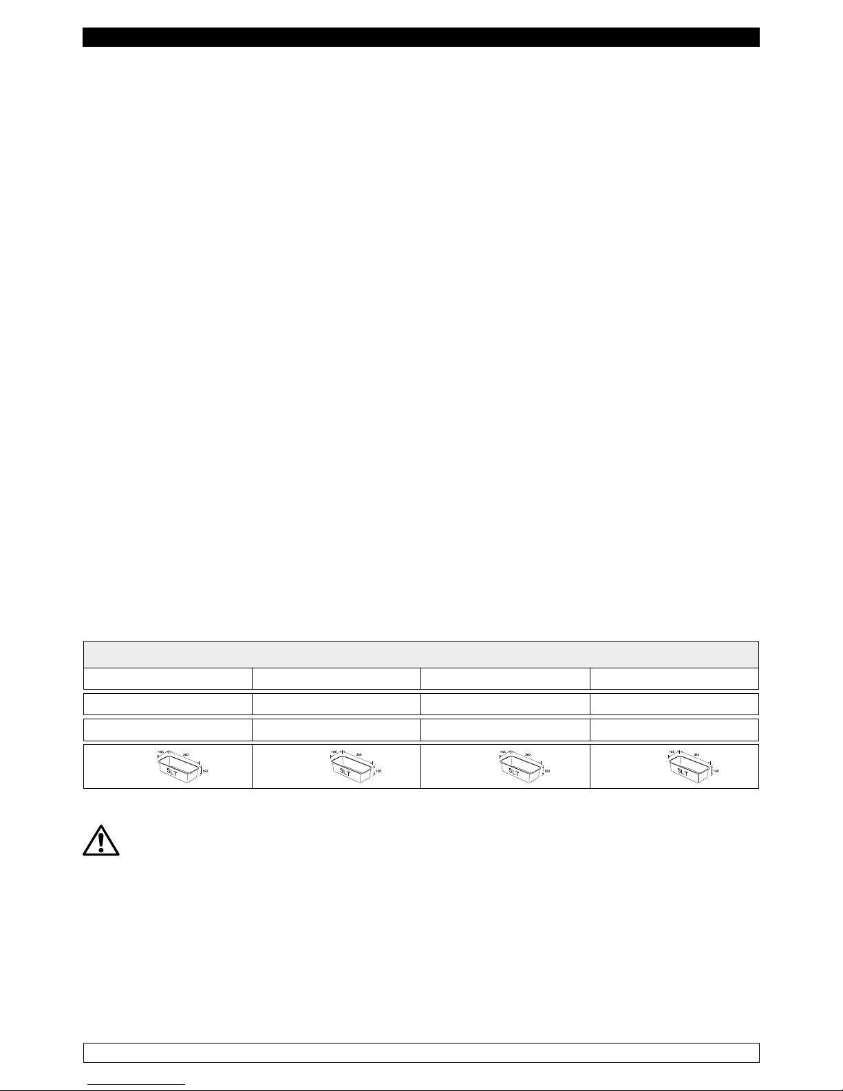
I prodotti devono essere stivati rispettando i limiti di carico riportati in tabella allo scopo di assicurare
una circolazione efficace dell’aria all’interno dell’abbattitore di temperatura.
Capacità di carico
PROF ABF 05 PROF ABF 10 PROF ABF 15 PROF ABF 20
5 x GN 1/1 10 x GN 1/1 15 x GN 1/1 20 x GN 1/1
5 x EN 60x40 10 x EN 60x40 15 x EN 60x40 20 x EN 60x40
6 x 12 x 18 x 24 x
L’installazione deve essere effettuata esclusivamente da un tecnico specializzato
1.1 Proibizione della rimozione dei ripari e dei dispositivi di sicurezza
E’ assolutamente vietata la rimozione delle protezioni di sicurezza.
Il fabbricante si esime da qualsiasi responsabilità per incidenti dovuti all’inadempienza del suddetto
obbligo.
Page 4
3
ITALIANO
1.2 Indicazioni sulle operazioni di emergenza in caso di incendio
- staccare l’abbattitore di temperatura dalla presa elettrica oppure interrompere l’alimentazione
generale
- non utilizzare getti d’acqua
- usare estintori a polvere o CO2
CAPITOLO 2 PULIZIA DELL’ABBATTITORE DI TEMPERATURA
Poiché nell’abbattitore di temperatura vanno conservati dei prodotti alimentari è necessaria l’operazione
di pulizia ai fini dell’igiene e della tutela della salute. La pulizia dell’abbattitore di temperatura è già
stata effettuata in fabbrica. Si suggerisce tuttavia di effettuare un ulteriore lavaggio delle parti interne
prima dell’uso, assicurandosi che il cavo di alimentazione sia scollegato.
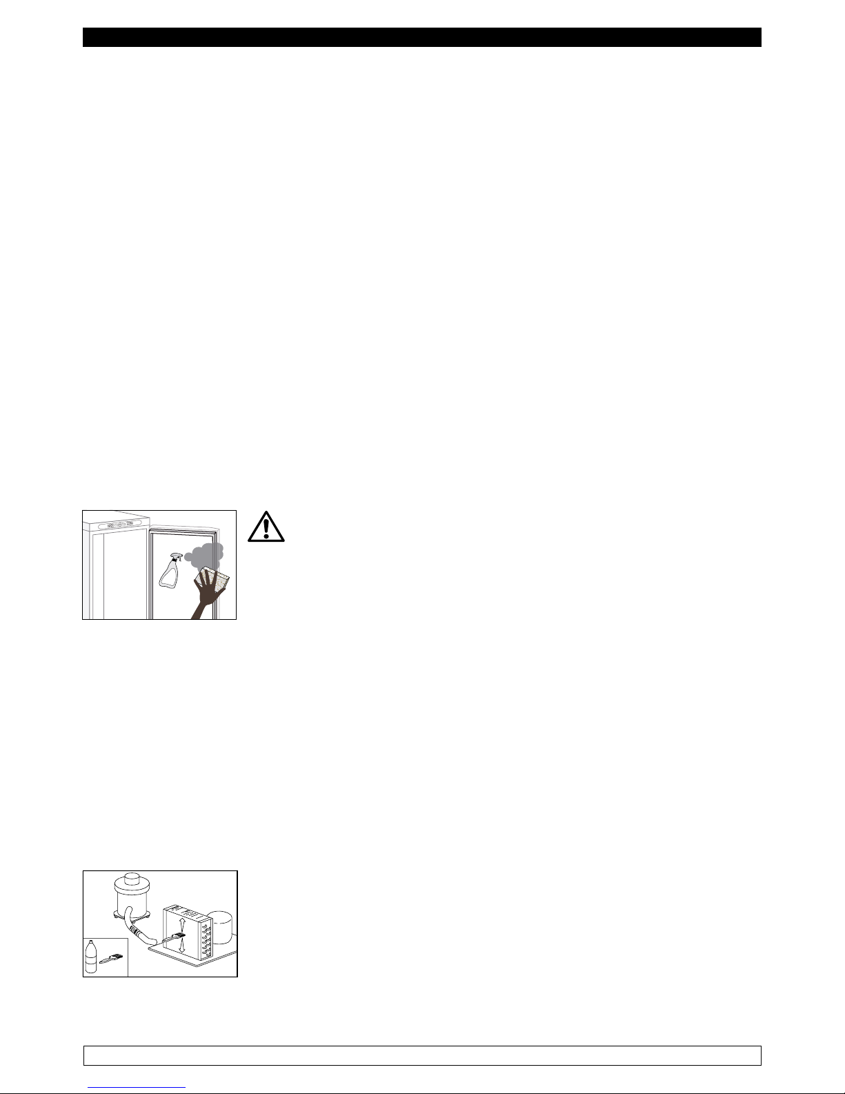
2.1 Pulizia del mobile interno ed esterno
Allo scopo vengono indicati
- i prodotti di pulizia : acqua e detergenti neutri non abrasivi. NON USARE SOLVENTI E DILUENTI
- i metodi di pulizia : lavare le parti interne ed esterne con acqua tiepida e sapone neutro o con panno
o spugna con prodotti idonei
- la disinfezione : evitare sostanze che possano alterare le caratteristiche organolettiche degli alimenti
- la risciacquatura : panno o spugna imbevuti d’acqua tiepida. NON USARE GETTI D’ACQUA
- la frequenza : si consiglia settimanale, l’utilizzatore può stabilire frequenze diverse in funzione del
tipo di alimenti conservati.
IMPORTANTE: Pulire frequentemente le guarnizioni delle porte.
Alcuni prodotti conservati protrebbero rilasciare degli enzimi che attaccano la
guarnizione deteriorandola molto velocemente. Per la pulizia utilizzare prodotti
specici disponibili a richiesta anche presso la nostra rete commerciale.
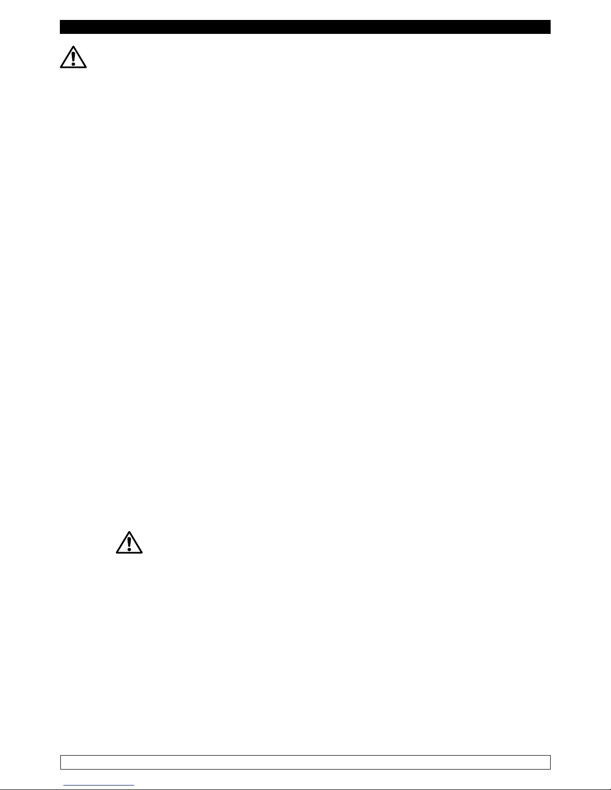
2.2 Pulizia del condensatore
L’efficienza dell’abbattitore di temperatura è compromessa dall’intasamento del condensatore per cui
è necessario provvedere alla pulizia dello stesso con frequenza mensile. Prima di effettuare questa
operazione spegnere l’abbattitore di temperatura, disinserire il cavo di alimentazione e procedere
come segue :
Motore in basso - aprire il frontale portacomandi svitando le apposite viti e facendolo ruotare sulle
cerniere poste in basso.
Motore in alto - per i modelli con frontale fisso non ribaltabile, salire su una scaletta sicura e accedere
direttamente al condensatore posto sulla parte superiore dell’abbattitore di temperatura.
Con l’ausilio di un getto d’aria o pennello asciutto eliminare, con movimento
verticale ( Fig. 1 ), la polvere e la lanuggine depositata sulle alette. Nel caso
di depositi untuosi si consiglia l’impiego di un pennello imbevuto di appositi
detergenti. Per i modelli con frontale ribaltabile, svitare la vite di blocco e
ruotare il frontale sulle cerniere poste in alto. A questo punto procedere alla
pulizia come per i modelli a frontale fisso.
Ad operazione ultimata avviare nuovamente l’abbattitore di temperatura.
A
L
C
O
O
L
Fig.1
Page 5
4
ITALIANO
Durante questa operazione usare i seguenti dispositivi di protezione individuali : occhiali,
maschera di protezione delle vie respiratorie, guanti resistenti agli agenti chimici ( benzine-alcool ).
CAPITOLO 3 VERIFICHE PERIODICHE DA ESEGUIRE
Di seguito vengono elencati i punti o i gruppi dell’abbattitore di temperatura che necessitano di
verifiche periodiche :
- integrità ed efficienza delle guarnizioni delle porte
- integrità delle griglie a contatto con gli alimenti
- integrità delle cerniere di fissaggio delle porte
- integrità del cavo di alimentazione dell’Abbattitore
3.1 PRECAUZIONI IN CASO DI LUNGA INATTIVITA’
Per lunga inattività si intende un periodo di fermo superiore a 15 giorni.
E’ necessario procedere come segue :
- spegnere l’abbattitore di temperatura e scollegarlo dall’alimentazione elettrica
- effettuare la pulizia accurata del mobile interno, ripiani, vassoi, guide e supporti con particolare
attenzione ai punti critici quali giunzioni e guarnizioni magnetiche, secondo le indicazioni riportate
al capitolo 2.
- lasciare le porte semiaperte per evitare il ristagno d’aria e umidità residua
CAPITOLO 4 MANUTENZIONE PREVENTIVA
4.1 Riavvio dopo lunga inattività
Il riavvio dopo lunga inattività è un evento che richiede un intervento di manutenzione preventiva.
E’ necessario eseguire una accurata pulizia come descritto nel capitolo 2.
4.2 Controllo dei dispositivi di avvertimento e comando
Si consiglia di richiedere al rivenditore un contratto di assistenza o manutenzione periodica che
comprenda :
- pulizia del condensatore
- verifica della carica del fluido frigorigeno
- verifica del funzionamento a ciclo completo
- sicurezza elettrica
CAPITOLO 5 MANUTENZIONE STRAORDINARIA E RIPARAZIONE
Tutti gli interventi di manutenzione che non sono stati descritti nei capitoli precedenti sono da
considerare “ Manutenzione Straordinaria “. La manutenzione straordinaria e la riparazione sono
compiti riservati esclusivamente al personale specializzato ed autorizzato dal fabbricante.
Si declina ogni responsabilità per interventi condotti dall’utilizzatore, da personale non autorizzato,
o per l’utilizzo di ricambi non originali.
Page 6
5
ITALIANO
CAPITOLO 6 DIAGNOSTICA
Possono verificarsi degli inconvenienti, nell’abbattitore di temperatura, evidenziati come esposto in tabella:
DESCRIZIONE GUASTO POSSIBILI CAUSE RIMEDIO
l’abbattitore di temperatura non si
accende
manca tensione elettrica verificare spina, presa, fusibili, linea
altro contattare assistenza tecnica
il gruppo frigorifero non parte raggiunta temperatura impostata impostare nuova temperatura
sbrinamento in corso
attendere fine ciclo / spegnere e riaccendere
pannello comando in avaria contattare assistenza tecnica
altro contattare assistenza tecnica
il gruppo frigorifero funziona continuamente ma non raggiunge la temperatura impostata
locale troppo caldo aerare maggiormente
condensatore sporco pulire il condensatore
fluido frigorigeno insufficiente contattare assistenza tecnica
arresto ventola condensatore contattare assistenza tecnica
tenuta insufficiente sportelli
verificare guarnizioni / disposizione della
merce
evaporatore brinato completamente sbrinamento manuale
altro contattare assistenza tecnica
il gruppo frigorifero non si ferma alla
temperatura impostata
pannello comando in avaria contattare assistenza tecnica
sonda temperatura cella in avaria ER0 contattare assistenza tecnica
blocco di ghiaccio sull’evaporatore
uso improprio vedi capitolo 1.
resistenza sbrinamento guasta contattare assistenza tecnica
sonda sbrinamento in avaria ER1 contattare assistenza tecnica
ristagno di acqua o ghiaccio nel gocciolatoio
scarico ostruito pulire la pipetta e lo scarico
abbattitore di temperatura non livellato verificare livellamento
CAPITOLO 7 ISTRUZIONI PER LA RICHIESTA DI INTERVENTI
Per qualsiasi problema di carattere tecnico, e le eventuali richieste di intervento o assistenza, è
necessario rivolgersi esclusivamente presso il proprio rivenditore.
CAPITOLO 8 SICUREZZA ED ANTINFORTUNISTICA
L’abbattitore di temperatura è stato realizzato con gli opportuni accorgimenti al fine di garantire la
sicurezza e la salute dell’utilizzatore.
Di seguito vengono elencate le misure adottate per la protezione contro i rischi meccanici :
- stabilità : L’abbattitore di temperatura, anche con griglie estratte, è stato progettato e costruito
in modo che nelle condizioni di funzionamento previste, la sua stabilità sia tale da consentirne
l’utilizzazione senza rischio di rovesciamento, di caduta o di spostamento intempestivo
- superfici, spigoli, angoli : gli elementi accessibili dell’abbattitore di temperatura sono privi, entro i
limiti consentiti dalle loro funzioni, di angoli acuti e spigoli vivi, nonché di superfici rugose che possano
causare lesioni
- elementi mobili : sono stati progettati, costruiti e disposti per evitare rischi. Talune parti sono munite
di protezioni fisse in modo tale da prevenire rischi di contatto che possono provocare infortuni
Page 7
6
ITALIANO
Di seguito vengono elencate le misure adottate per la protezione contro altri rischi :
- energia elettrica : L’abbattitore di temperatura è stato progettato, costruito ed equipaggiato in modo
da prevenire i rischi elettrici, nel rispetto della normativa specifica vigente
- rumore : L’abbattitore di temperatura è stato progettato e costruito in modo tale che i rischi dovuti
all’emissione di rumore aereo siano ridotti al livello minimo
8.1 dispositivi di sicurezza adottati
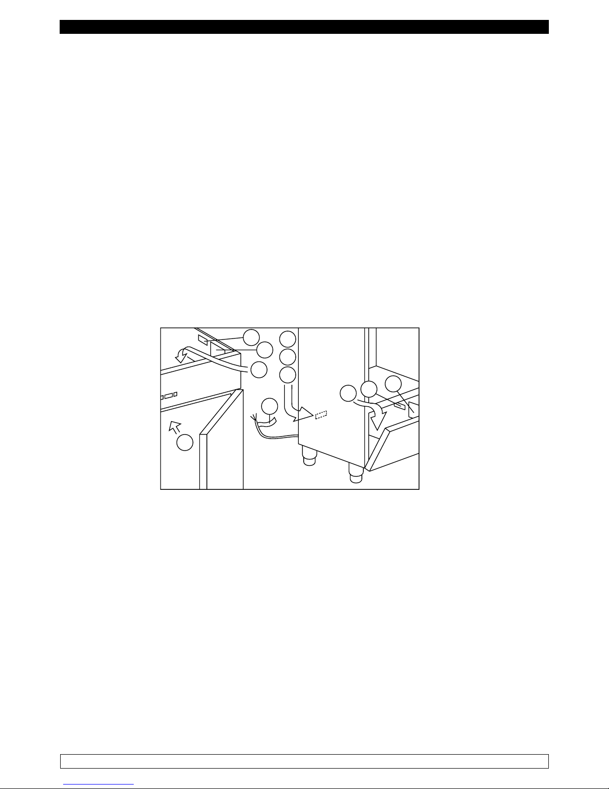
E’ assolutamente vietato ( Fig. 2 ) :
- manomettere o asportare l’involucro copri-evaporatore che protegge l’utilizzatore dal rischio di taglio
delle lamelle dell’evaporatore e dal movimento del motoventilatore interno
- rimuovere le targhette applicate in corrispondenza del bordo interno del vano-motore indicanti le
caratteristiche tecniche ( 1 ) e le avvertenze per il collegamento della messa a terra ( 2 )
- rimuovere la targhetta, applicata sulla protezione dell’evaporatore e vicino al cablaggio elettrico all’interno
del vano motore, che avverte di escludere l’alimentazione prima di intervenire sull’apparecchio ( 3 )
- rimuovere le targhette, applicate all’interno del vano-motore, indicanti la messa a terra ( 4 )
- rimuovere la targhetta, applicata sul cavo di alimentazione, indicante il tipo di alimentazione ( 5 )
Il fabbricante declina qualsiasi responsabilità sulla sicurezza dell’abbattitore di temperatura se questo
dovesse accadere.
1
2
3
4
5
4
2
3
1
2
3
Fig.2
8.2 Indicazioni per il funzionamento ottimale
- non ostruire le prese d’aria del vano-motore
- disporre le derrate alimentari sugli appositi ripiani o contenitori. Non disporle direttamente sul fondo,
né addossate alle pareti, alle porte o alle protezioni fisse
- richiudere accuratamente le porte
- tenere sempre sgombro il foro di scarico dell’acqua di sbrinamento
- limitare, per quanto possibile, la frequenza di apertura delle porte e la loro durata. Ogni apertura
provoca un cambiamento della temperatura interna
- effettuare periodicamente la manutenzione ordinaria ( vedi capitolo 3 )
Page 8
7
ITALIANO
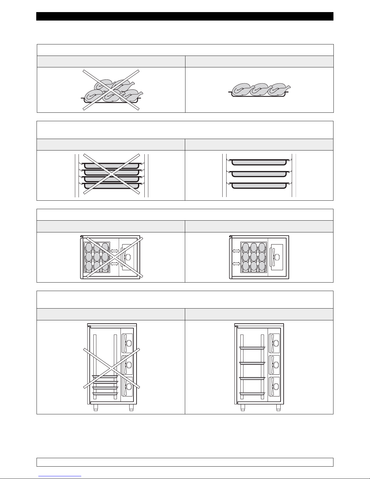
CORRETTO CARICO DELL’ABBATTITORE
Evitare di sovraccaricare l’abbattitore di temperatura oltre i limiti stabiliti indicati nella tabella
NO OK
Non disporre le teglie troppo vicine l’una dall’altra onde evitare un irregolare circolo dell’aria all’interno
dell’abbattitore di temperatura
NO OK
Non posizionare le teglie troppo lontane dall’evaporatore
NO OK
Evitare di concentrare in un unica zona dell’abbattitore di temperatura le teglie in caso il carico non
sia completo ma distribuirlo in altezza in modo omogeneo
NO OK
In caso di interruzione del circuito di alimentazione elettrica o di guasto evitare l’apertura delle porte
allo scopo di mantenere una temperatura omogenea all’interno dell’abbattitore di temperatura.
Se il problema ha una durata di più ore si consiglia lo spostamento del materiale in luogo adatto.
Page 9
8
ITALIANO
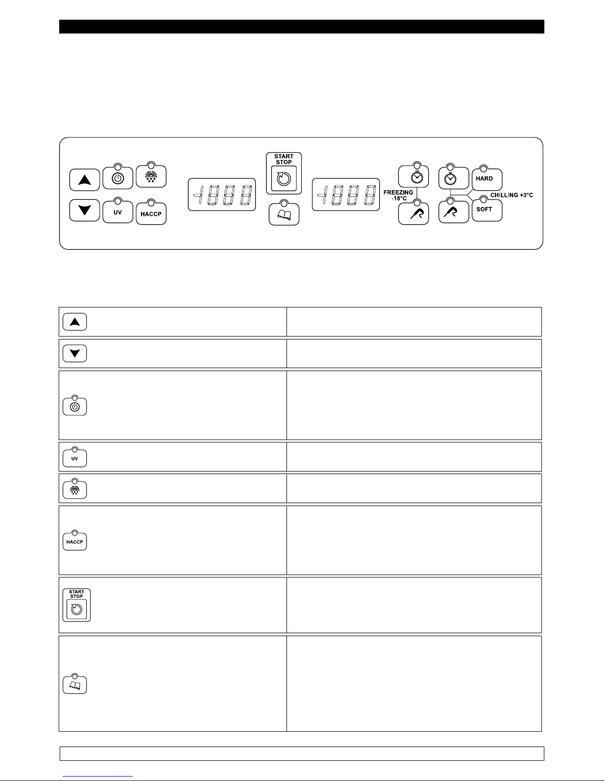
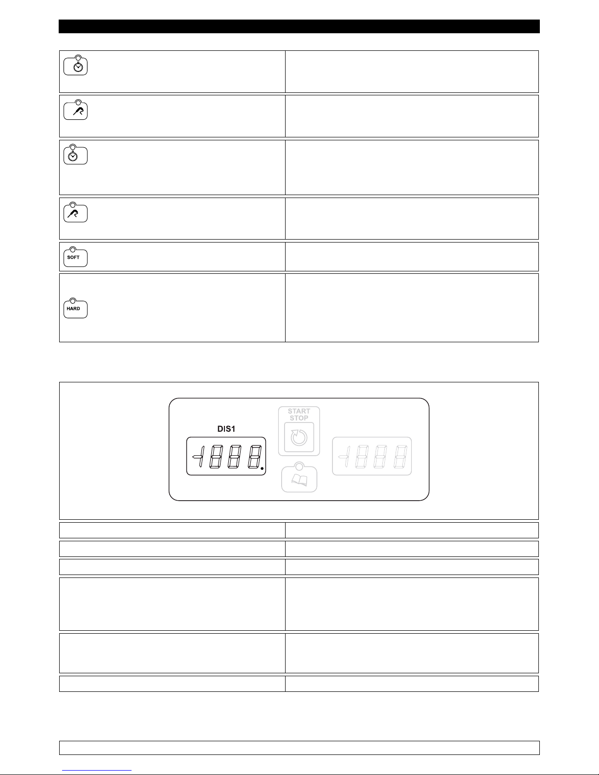
CAPITOLO 9 COMANDI
9.1 Descrizione dei comandi e pulsanti ( Fig. 3)
Il pannello di comando è un termoregolatore digitale per il freddo ed è provvisto di 14 pulsanti con
funzioni specifiche:
Fig.3
I pulsanti comando di cui è dotato l’abbattitore di temperatura sono:
INCREMENTO
Permette di incrementare il valore visualizzato sui
display.
DECREMENTO
Permette di decrementare il valore visualizzato sui
display.
ON/OFF
Con scheda in OFF: la pressione singola mette in
STANDBY la scheda.
Con scheda in STANDBY o con ciclo in corso: la
pressione continua per cinque secondi mette in
OFF la scheda.
STERILIZZAZIONE
Con scheda in STANDBY: la pressione singola
seleziona un ciclo di sterilizzazione.(Optional)
SBRINAMENTO
Con scheda in STANDBY: la pressione singola
seleziona ed avvia un ciclo di sbrinamento.
HACCP
Con scheda in OFF: la pressione continua per
cinque secondi permette di visualizzare lo storico
allarmi.
Con storico allarmi visualizzato: la pressione
singola permette di stampare lo storico.
START/STOP
Con ciclo selezionato: la pressione singola permette
di avviare l’esecuzione del ciclo.
Con ciclo in corso: la pressione singola permette di
terminare l’esecuzione del ciclo.
PROGRAMMI
Con scheda in STANDBY: la pressione singola
seleziona un programma prememorizzato.
Con ciclo selezionato: la pressione continua
per cinque secondi permette di entrare in
memorizzazione programmi.
Con visualizzazione Storico HACCP: la pressione
singola permette di scorrere i dati dello storico
Page 10
9
ITALIANO
SURGELAZIONE TEMPO
(Freezing -18°C)
Con scheda in STANDBY: la pressione singola
seleziona un ciclo di raffreddamento negativo
(surgelazione) a tempo.
SURGELAZIONE TEMPERATURA
(Freezing -18°C)
Con scheda in STANDBY: la pressione singola
seleziona un ciclo di raffreddamento negativo
(surgelazione) a temperatura.
RAFFREDDAMENTO A
TEMPERATURA POSITIVA A TEMPO
(Chilling +3°C)
Con scheda in STANDBY: la pressione singola
commuta il ciclo di raffreddamento selezionato nel
corrispondente a tempo.
RAFFREDDAMENTO A
TEMPERATURA POSITIVA (Chilling +3°C)
Con scheda in STANDBY: la pressione singola
commuta il ciclo di raffreddamento selezionato nel
corrispondente a temperatura.
SOFT
Con scheda in STANDBY: la pressione singola
seleziona un ciclo di raffreddamento positivo SOFT
HARD
Con scheda in STANDBY: la pressione singola
permette di selezionare un ciclo di raffreddamento
positivo hard. Con ciclo hard selezionato: la pressione
continua per cinque secondi permette di visualizzare
il setpoint cella della seconda fase del ciclo.
Display temperatura
► Con scheda in OFF: visualizza la label OFF.
► Con scheda in STANDBY: visualizza la temperatura in cella.
► Dopo un’interruzione elettrica: visualizza lampeggiante la label PF.
► Con ciclo selezionato:
visualizza il setpoint cella relativo al ciclo
selezionato.
In impostazione/selezione programmi:
visualizza la label relativa al programma scelto.
► Con un ciclo di sbrinamento in corso:
visualizza la label DEF.
In impostazione parametri:
visualizza la label relativa al parametro.
► Con visualizzazione Storico HACCP: visualizza le informazioni relative allo storico.
NOTA:Il puntino sul DIS1 del digit a destra si accende per segnalare l’ingresso di un nuovo
allarme nello storico.
Page 11
10
ITALIANO
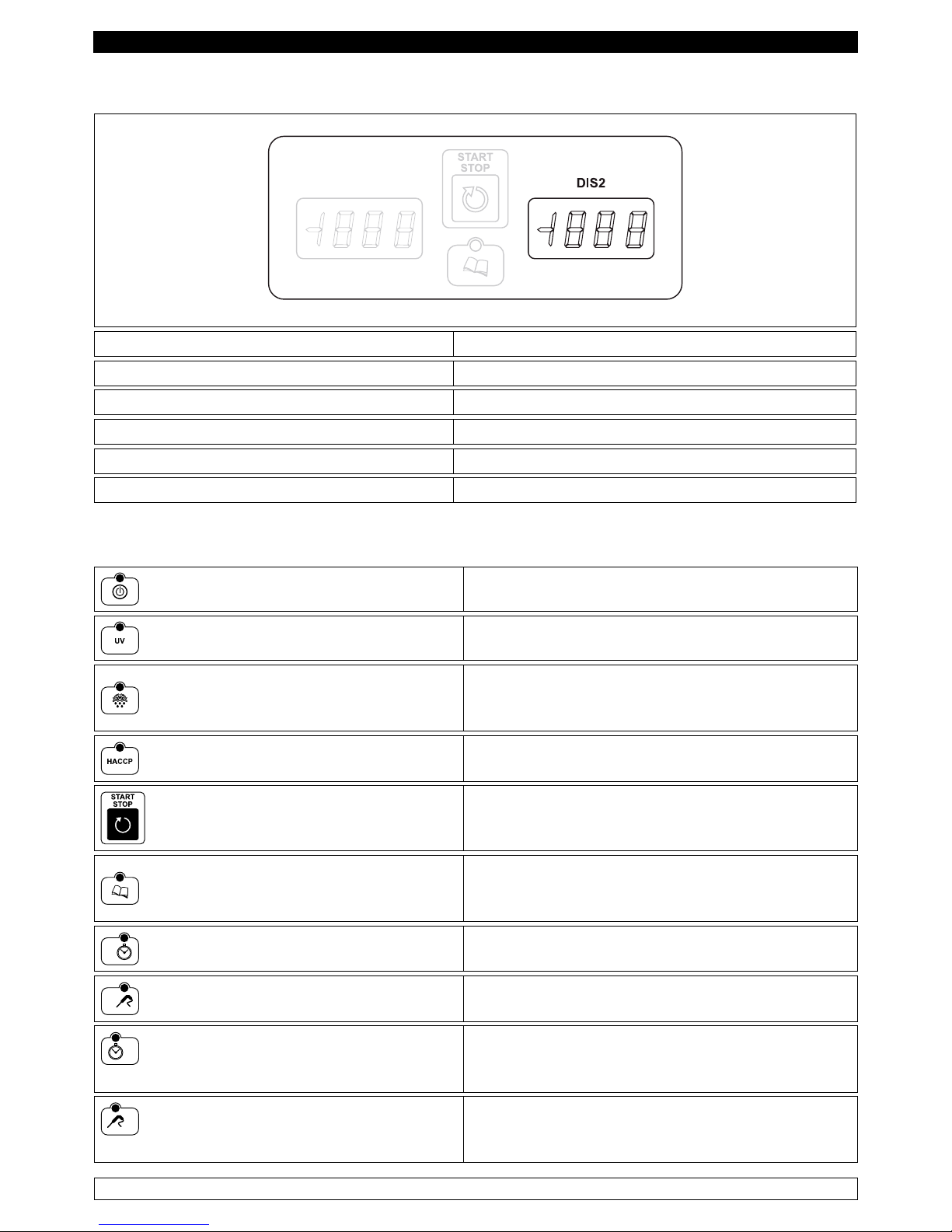
Display tempo
► Con scheda in OFF: è spento.
► Con scheda in STANDBY: visualizza tre trattini.
► Con ciclo a tempo selezionato: visualizza la durata del ciclo.
► Con ciclo a tempo in corso: visualizza il tempo in decremento.
► In impostazione parametri: visualizza il valore del parametro selezionato.
► Con visualizzazione Storico HACCP: visualizza le informazioni relative allo storico.
I Led di cui è dotato l’abbattitore di temperatura sono:
Led ON/OFF
Acceso con scheda in STANDBY o ON.
Led STERILIZZAZIONE
Acceso durante un ciclo di sterilizzazione.
Led SBRINAMENTO
Acceso durante un ciclo di sbrinamento manuale,
lampeggiante durante il conteggio dei tempi di
sgocciolamento.
Led HACCP
Acceso durante la visualizzazione dello storico
allarmi.
Led START/STOP
Acceso durante l’esecuzione di un ciclo,
lampeggiante durante la conservazione.
Led PROGRAMMI
Acceso se si è in impostazione/selezione
programmi e durante l’esecuzione di uno dei 99
programmi.
Led SURGELAZIONE TEMPO
Acceso se è selezionato un ciclo di surgelazione
a tempo.
Led SURGELAZIONE TEMPERATURA
Acceso se è selezionato un ciclo di surgelazione
a temperatura.
Led raffreddamento a temperatura
positiva a TEMPO
Acceso se è selezionato un ciclo di raffreddamento
soft o hard a tempo.
Led raffreddamento a temperatura
positiva a SPILLONE
Acceso se è selezionato un ciclo di raffreddamento
soft o hard a temperatura
Page 12
11
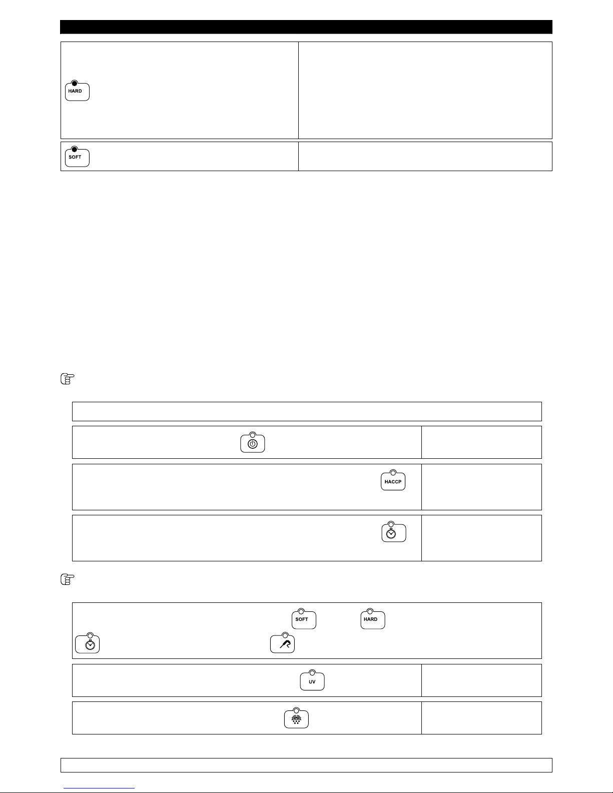
ITALIANO
Led HARD
Acceso se è selezionato un ciclo hard e si sta
visualizzando il setpoint cella della prima fase,
lampeggiante se si sta visualizzando il setpoint
della seconda fase.
Acceso se è in corso la prima fase di un ciclo hard,
lampeggiante durante l’esecuzione della seconda
fase.
Led RAFFREDDAMENTO SOFT
Acceso se è selezionato un ciclo di raffreddamento
positivo.
9.2 INDICAZIONI RELATIVE ALL’USO
9.2.1 Avviamento
Prima di effettuare l’avviamento dell’abbattitore di temperatura è necessario verificare che il
collegamento elettrico e l’allacciamento siano stati realizzati come previsto nel capitolo 15.
Quando la scheda viene alimentata, esegue un lamp-test accendendo tutti i led e display per cinque
secondi, trascorsi i quali si riporta nello stato in cui si trovava prima di essere disalimentata.
Se, prima del power down, era in corso un ciclo, questo viene ripreso dal punto in cui si era interrotto
e il display DIS1 visualizza la label “PF” lampeggiante, per indicare che si è vericata una mancanza
di tensione. Se prima della mancanza di tensione non era in corso un ciclo, il display DIS1 visualizza
la temperatura della sonda cella, mentre il display DIS2 visualizza tre trattini, in questo caso la
scheda è in STANDBY, si può selezionare un ciclo ed avviarne l’esecuzione.
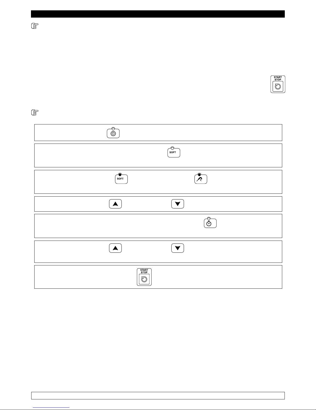
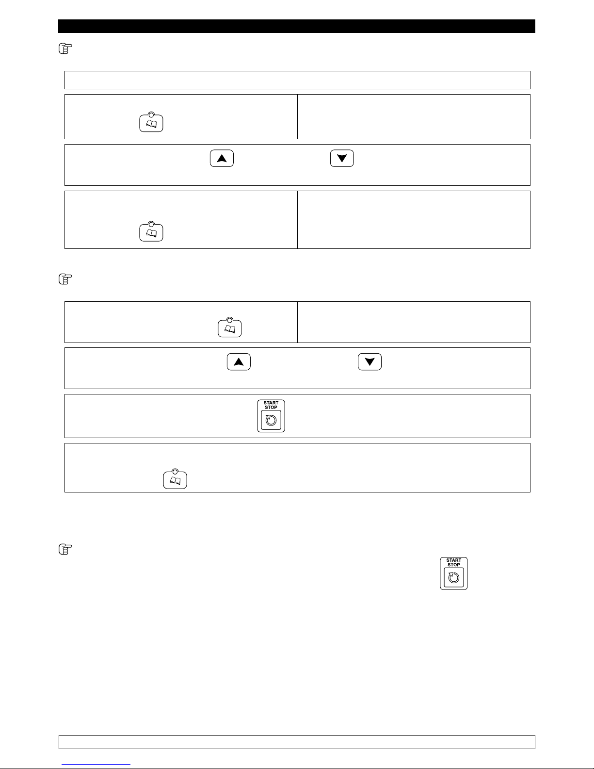
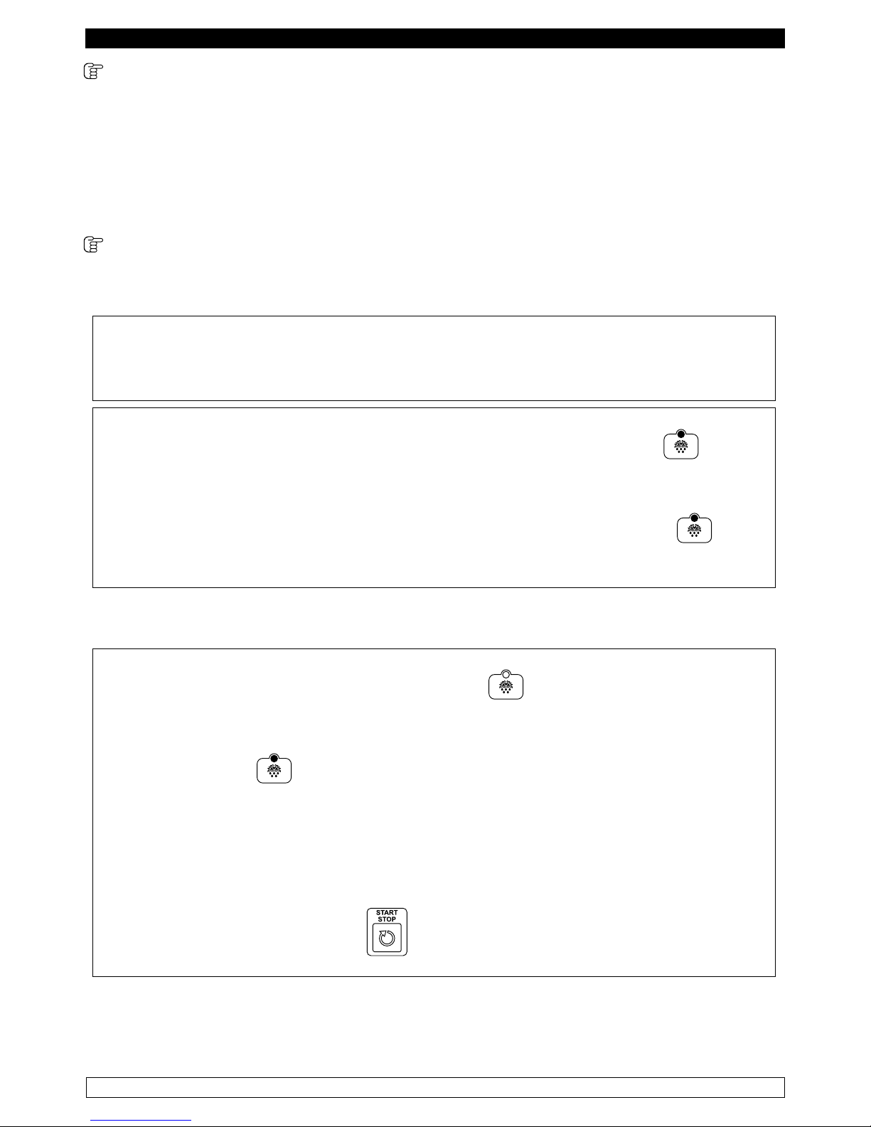
Con scheda in OFF :
il display DIS1 visualizza la label “OFF”, mentre il display DIS2 e tutti i led sono spenti.
► la pressione del tasto ON/OFF
mette la scheda in
STANDBY.
► la pressione continua per cinque secondi del tasto HACCP
permette di visualizzare
la lista allarmi presente
nello storico.
► la pressione continua per cinque secondi del tasto TEMPO
permette di attivare
l’impostazione di data
e ora.
Con scheda in STANDBY:
► La pressione dei tasti: RAFFREDDAMENTO o HARD , SURGELAZIONE TEMPO
, SURGELAZIONE TEMPERATURA permette di selezionare uno di questi cicli.
► La pressione del tasto STERILIZZAZIONE
permette di avviare un
ciclo di sterilizzazione.
► La pressione del tasto SBRINAMENTO
permette di avviare un
ciclo di sbrinamento.
Page 13
12
ITALIANO
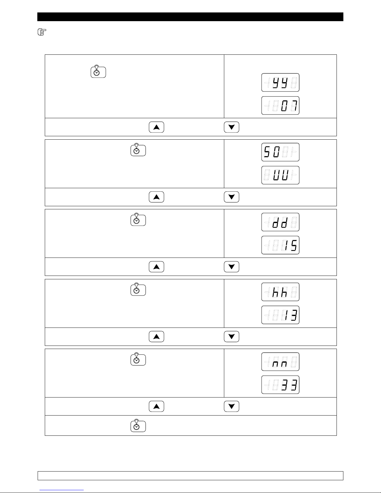
9.2.2 regolazione della data e dell’orologio interno sull’ora attuale (fig.3)
La prima operazione è la regolazione dell’orologio interno all’ora attuale così come segue:
► Con scheda in OFF premere per cinque secondi il
tasto TEMPO
Il gruppo display visualizza:
► Premere i tasti INCREMENTO e DECREMENTO per impostare l’anno.
► Premere il tasto TEMPO per passare
all’impostazione del mese:
► Premere i tasti INCREMENTO e DECREMENTO per impostare il mese.
► Premere il tasto TEMPO per passare
all’impostazione del giorno:
► Premere i tasti INCREMENTO e DECREMENTO per impostare il giorno.
► Premere il tasto TEMPO per passare
all’impostazione dell’ora:
► Premere i tasti INCREMENTO e DECREMENTO per impostare l’ora.
► Premere il tasto TEMPO per passare
all’impostazione dei minuti:
► Premere i tasti INCREMENTO e DECREMENTO per impostare i minuti.
► Premere il tasto TEMPO per tornare in OFF.
Terminata la regolazione non operare sullo strumento per 60 secondi, automaticamente uscirà dalla
procedura
Page 14
13
ITALIANO
9.2.3 Selezione cicli (fig.3)
Con scheda in STANDBY è possibile selezionare un ciclo di raffreddamento/surgelazione. I cicli
possono essere controllati dalla temperatura dello spillone o da un tempo. Qualora siano controllati
dalla temperatura dello spillone, il termine della fase di raffreddamento avviene quando la sonda
spillone raggiunge il setpoint di fine raffreddamento/surgelazione, mentre se è stata definita una
durata per la fase di raffreddamento/surgelazione, il termine avviene allo scadere del tempo
impostato. Per entrambi i tipi di ciclo, una volta terminata la fase di raffreddamento/surgelazione
inizia la fase di conservazione, il cui termine è definito dalla pressione del tasto START/STOP
, che mette la scheda in STANDBY.
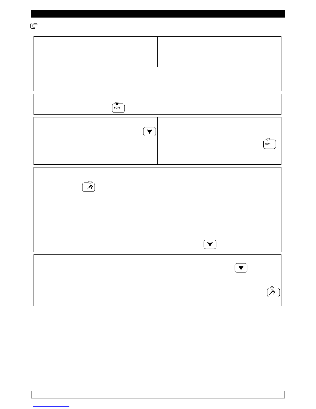
CICLO DI RAFFREDDAMENTO A TEMPERATURA POSITIVA
► Premere il tasto ON/OFF
► La pressione del tasto RAFFREDDAMENTO permette di selezionare un ciclo di
raffreddamento positivo. Di default il ciclo selezionato è controllato dalla temperatura dello spillone.
► Il led RAFFREDDAMENTO e il led
TEMPERATURA sono accesi. Il display DIS1
visualizza il setpoint cella, mentre il display DIS2 visualizza tre trattini
.
► Con i tasti INCREMENTO e DECREMENTO si può modificare il setpoint cella.
► Per commutare il ciclo in uno a tempo premere il tasto TEMPO .
Il display DIS2 visualizza il tempo.
► Con i tasti INCREMENTO e DECREMENTO si può modificare il tempo.
Le modifiche apportate sono solo temporanee e non vengono memorizzate.
► La pressione del tasto START/STOP avvia l’esecuzione del ciclo.
NOTA: Il valore minimo impostabile per il setpoint cella è -2°C ed il massimo è 99°C.
Il valore minimo impostabile per il tempo è 0 minuti, il massimo è 400 minuti.
Page 15
14
ITALIANO
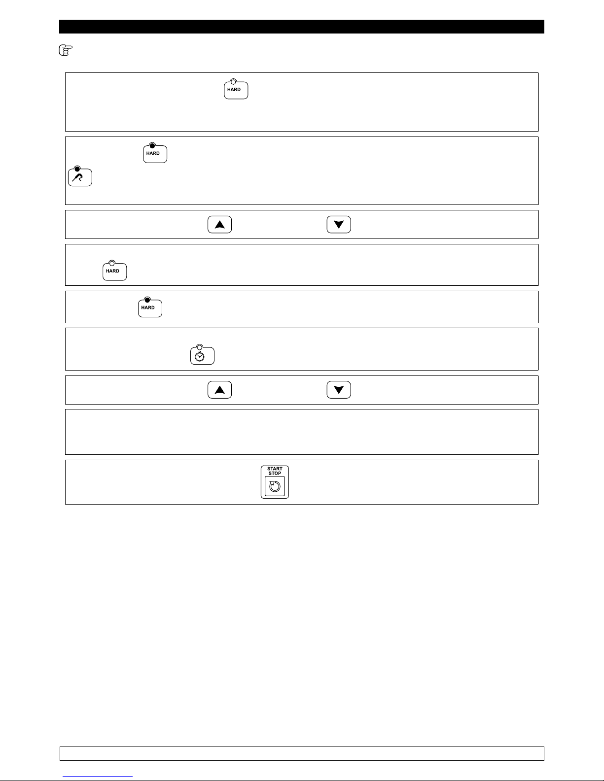
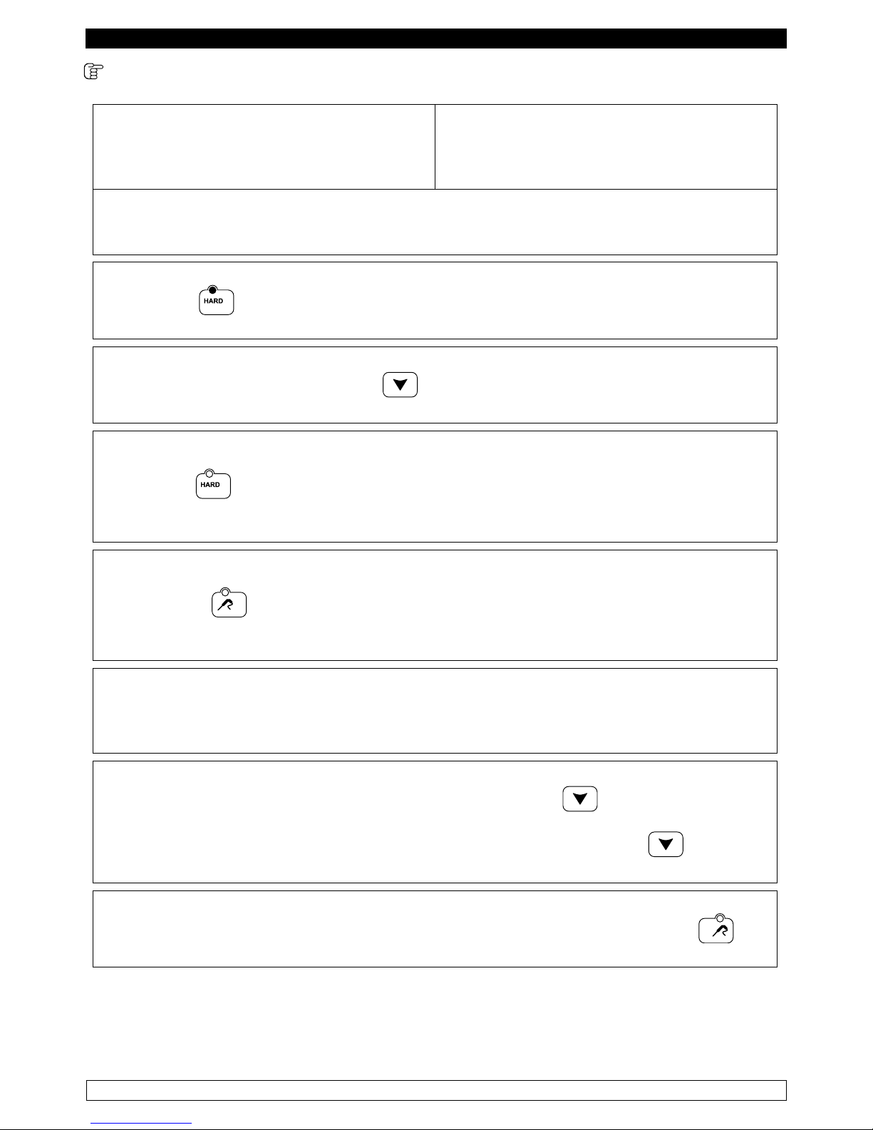
CICLO DI RAFFREDDAMENTO A TEMPERATURA POSITIVA HARD
► La pressione del tasto HARD permette di selezionare un ciclo di raffreddamento HARD.
Questo tipo di ciclo è suddiviso in due fasi, con due setpoint cella diversi.
Di default il ciclo selezionato è controllato dalla temperatura dello spillone.
► Il led HARD ed il led TEMPERATURA
sono accesi.
Il display DIS1 visualizza il setpoint cella della
prima fase, mentre il display DIS2 visualizza tre
trattini.
► Con i tasti INCREMENTO e DECREMENTO si può modificare il setpoint cella.
► Per modificare il setpoint cella della seconda fase tenere premuto per cinque secondi il tasto
HARD
► il led HARD lampeggia ed il display DIS1 visualizza il setpoint cella della seconda fase.
► Per commutare il ciclo in un ciclo a tempo
premere il tasto TEMPO
.
Il display DIS2 visualizza il tempo.
► Con i tasti INCREMENTO e DECREMENTO si può modificare il tempo.
Tale valore non può superare il valore del parametro, in quanto questo definisce la durata
complessiva di tutto il ciclo di raffreddamento hard.
Le modifiche apportate sono solo temporanee e non vengono memorizzate.
► La pressione del tasto START/STOP avvia l’esecuzione del ciclo
NOTA: Il valore minimo impostabile per il setpoint cella è -2°C ed il massimo è 99°C. Il valore
minimo impostabile per il tempo è 0 minuti.
Page 16
15
ITALIANO
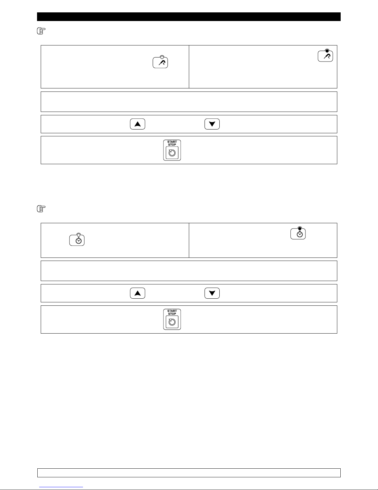
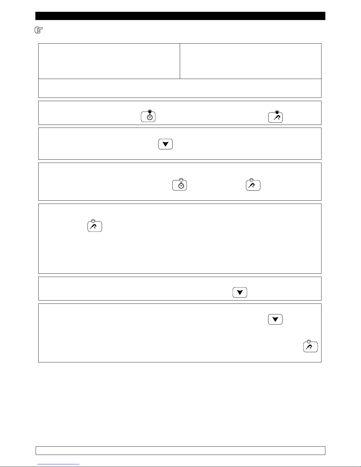
CICLO DI SURGELAZIONE A TEMPERATURA CON SONDA A SPILLONE
► La pressione del tasto
SURGELAZIONE TEMPERATURA
permette di selezionare un ciclo di
raffreddamento negativo a temperatura.
Il led SURGELAZIONE TEMPERATURA
è acceso.
► Il display DIS1 visualizza il setpoint temperatura cella, mentre il display DIS2 visualizza tre
trattini.
► Con i tasti INCREMENTO e DECREMENTO si può modificare il setpoint cella.
► La pressione del tasto START/STOP avvia l’esecuzione del ciclo.
NOTA: Il valore minimo impostabile per il setpoint cella è -40°C ed il massimo è 99°C. Il valore
minimo impostabile per il tempo è 0 minuti, il massimo è 400 minuti.
CICLO DI SURGELAZIONE A TEMPO
► La pressione del tasto SURGELAZIONE
TEMPO permette di selezionare un ciclo
di raffreddamento negativo a tempo.
Il led SURGELAZIONE TEMPO
è
acceso.
► Il display DIS1 visualizza il setpoint temperatura cella,mentre il display DIS2 visualizza il
tempo.
► Con i tasti INCREMENTO e DECREMENTO si può modificare il tempo.
► La pressione del tasto START/STOP avvia l’esecuzione del ciclo
Le modifiche apportate sono solo temporanee e non vengono memorizzate.
NOTA: Il valore minimo impostabile per il setpoint cella è -40°C ed il massimo è 99°C. Il valore
minimo impostabile per il tempo è 0 minuti, il massimo è 400 minuti.
Page 17
16
ITALIANO
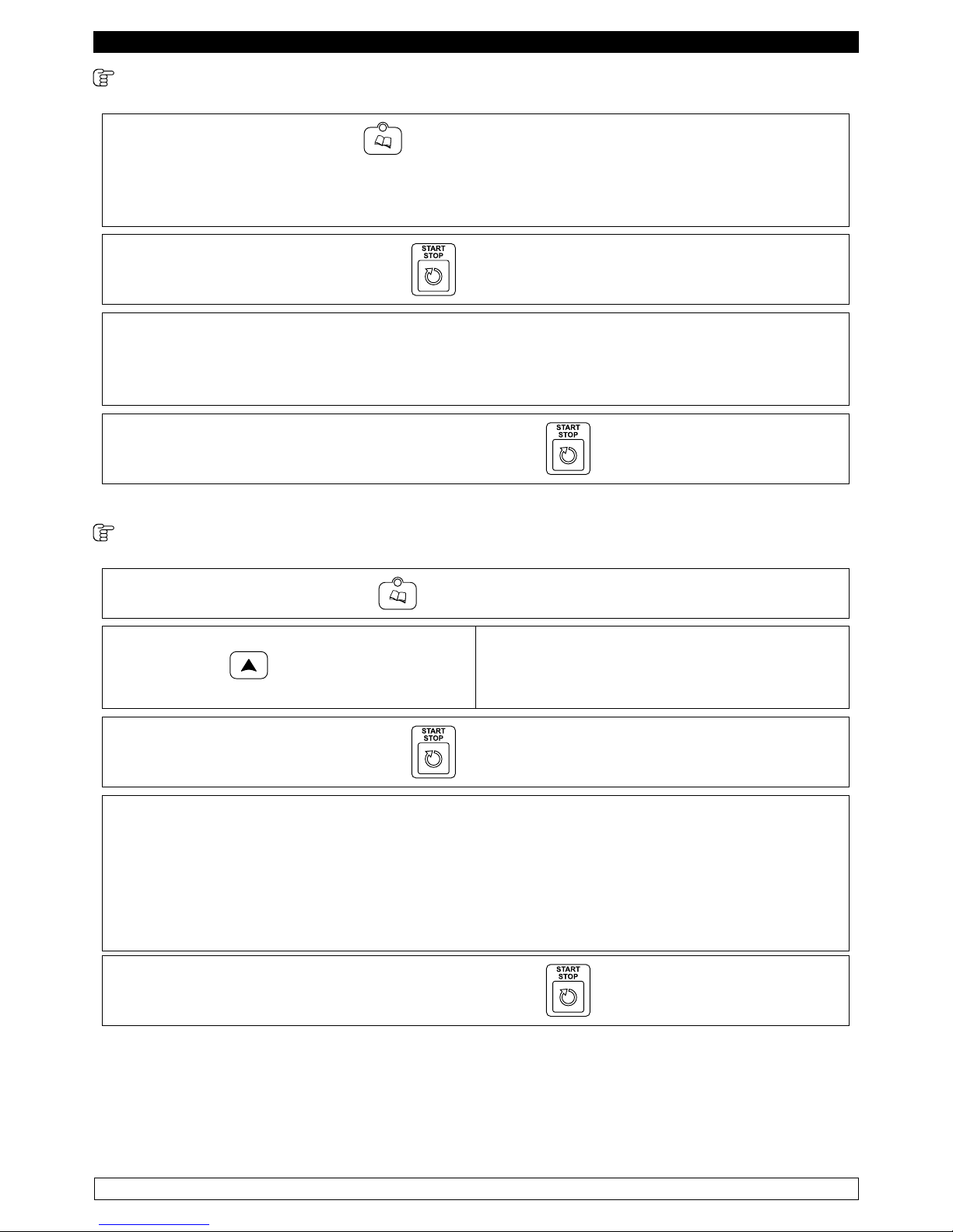
CICLO DI SCONGELAMENTO (Opt.)
Premendo il tasto PROGRAMMI si abilita la funzione scongelamento.
Il display DS1 visualizza la label “thA”, il display DS2 visualizza la durata dello scongelamento.
La durata è espressa in ore pari a 5,59 i minuti non sono visualizzabili (modicabile da parametro
dal servizio tecnico).
► La pressione del tasto START/STOP permette di avviare il ciclo.
Quando scade il tempo impostato, il buzzer suona e si avvia un mantenimento alle stesse
temperature tenute per il ciclo di scongelamento (6°C). La visualizzazione del tempo è fatta in
ore fino all’ultima ora.
Il dotpoint del terzo digit del display DS2 lampeggia per indicare che il ciclo è in corso.
► Il ciclo si blocca alla pressione del tasto START/STOP
CICLO SANIFICAZIONE PESCE
► Premendo il tasto PROGRAMMI .
► Premendo a questo punto il tasto
INCREMENTO si seleziona la funzione
di Sanificazione Pesce “SAn”
Il display DS1 visualizza la label “SAn”,
il display DS2 visualizza tre trattini.
► La pressione del tasto START/STOP permette di avviare il ciclo
La sanificazione pesce prevede l’esecuzione di tre cicli, il primo con controllo sulla temperatura
sonda spillone, il secondo a tempo (24h) ed il terzo infinito. Al raggiungimento della lettura sonda
spillone -20°C passa automaticamente al secondo ciclo a tempo della durata di 24h con temp.
-20°C, allo scadere del tempo il buzzer suona ed inizia l’ultima fase che corrisponde ad una
conservazione (durata infinito) sempre alla temperatura di -20°C. Se durante il primo ciclo, dopo
il controllo inserimento spillone, lo spillone non risulta inserito il display DS2 visualizza la label
“ALL” ed il ciclo di sanificazione viene interrotto
► Il ciclo si blocca alla pressione del tasto START/STOP
Page 18
17
ITALIANO
9.2.4 Memorizzazione programmi
► Selezionare un ciclo di raffreddamento/surgelazione a temperatura o a tempo.
► Quindi premere per cinque secondi il tasto
PROGRAMMI
.
Il display DIS1 visualizza “P” seguita dal numero
del primo programma libero
► Con i tasti INCREMENTO e DECREMENTO è possibile scegliere il numero del
programma che si desidera memorizzare.
La memorizzazione del ciclo selezionato
avviene premendo per cinque secondi il tasto
PROGRAMMI
.
Se si seleziona un programma che era già
scritto, questo viene cancellato e riscritto.
Sono disponibili 99 programmi.
9.2.5 Selezione programmi
► Per richiamare un programma memorizzato
premere il tasto PROGRAMMI .
Il display DIS1 visualizza “P 1”
► Con i tasti INCREMENTO e DECREMENTO si seleziona il programma
desiderato.
► La pressione del tasto START/STOP avvia l’esecuzione del programma.
►
Durante l’esecuzione del programma è possibile vedere il numero del programma premendo il
tasto PROGRAMMI
.
I programmi memorizzati sono dei normali cicli di raffreddamento/surgelazione.
9.2.6 visualizzazione stato cicli
Dopo aver selezionato un ciclo la pressione del tasto START/STOP
ne avvia la
visualizzazione.
Le modalità di esecuzione dei cicli è riportata nei paragrafi seguenti.
Page 19
18
ITALIANO
9.2.7 VISUALIZZAZIONE DEL CICLO DI RAFFREDDAMENTO A TEMPERATURA POSITIVA
► Il display DIS1 visualizza la temperatura
della sonda spillone per i cicli a temperatura
o la temperatura della sonda cella per i cicli a
tempo.
► Il display DIS2 visualizza il tempo in
decremento sia per i cicli a temperatura che per
i cicli a tempo.
Il tempo utilizzato per i cicli a temperatura è dato dal valore del parametro.
Per i cicli a temperatura il decremento del tempo inizia solo se la temperatura dello spillone è al
di sotto del valore.
► Il led RAFFREDDAMENTO
è acceso.
► La pressione del tasto DECREMENTO
permette di visualizzare su DIS2 il tempo
trascorso dall’inizio della fase di raffreddamento.
Durante un ciclo a temperatura è possibile
visualizzare la temperatura della sonda cella
premendo il tasto RAFFREDDAMENTO
.
La visualizzazione permane sul display per
cinque secondi.
►
Durante un ciclo a tempo è possibile visualizzare la temperatura della sonda spillone premendo
il tasto SPILLONE .
La visualizzazione permane sul display per cinque secondi.
Quando la temperatura dello spillone raggiunge il valore definito per un ciclo a temperatura, o
scade il tempo impostato per un ciclo a tempo, il ciclo di raffreddamento termina, il buzzer suona
ed inizia la fase di conservazione.
► Il buzzer può essere tacitato premendo il tasto DECREMENTO
.
► Durante la fase di conservazione la pressione del tasto DECREMENTO
permette di
visualizzare la durata complessiva della fase di raffreddamento.
► E’ possibile visualizzare la temperatura dello spillone premendo il tasto TEMPERATURA
, la visualizzazione permane sul display per cinque secondi.
NOTA: Se la temperatura dello spillone non raggiunge il setpoint entro il tempo definito, il display
DIS2 lampeggia, il ciclo continua comunque fino al raggiungimento del setpoint.
Page 20
19
ITALIANO
9.2.8 VISUALIZZAZIONE DEL CICLO DI RAFFREDDAMENTO HARD
► Il display DIS1 visualizza la temperatura
della sonda spillone per i cicli a temperatura
o la temperatura della sonda cella per i cicli a
tempo.
► Il display DIS2 visualizza il tempo in
decremento sia per i cicli a temperatura che per
i cicli a tempo.
Il tempo utilizzato per i cicli a temperatura è dato dal valore del parametro.
Per i cicli a temperatura il decremento del tempo inizia solo se la temperatura dello spillone è al
di sotto del valore
► Il led HARD
è acceso durante la prima fase, mentre lampeggia durante la seconda fase
del ciclo.
► La pressione del tasto DECREMENTO
permette di visualizzare su DIS2 il tempo trascorso
dall’inizio del ciclo.
►
Durante un ciclo a temperatura è possibile visualizzare la temperatura della sonda cella premendo
il tasto HARD
.
La visualizzazione permane sul display per cinque secondi.
►
Durante un ciclo a tempo è possibile visualizzare la temperatura della sonda spillone premendo il tasto
TEMPERATURA
.
La visualizzazione permane sul display per cinque secondi.
Quando la temperatura dello spillone raggiunge il setpoint, o scade il tempo impostato per un
ciclo a tempo, la prima fase termina ed avviene automaticamente il passaggio alla seconda che
termina quando la temperatura dello spillone raggiunge il valore definito o scade il tempo. Il
buzzer suona ed inizia la fase di conservazione.
► Il buzzer può essere tacitato premendo il tasto DECREMENTO
.
► Durante la fase di conservazione la pressione del tasto DECREMENTO
permette di
visualizzare la durata complessiva del ciclo hard.
► E’ possibile visualizzare la temperatura dello spillone premendo il tasto
SPILLONE
, la
visualizzazione permane sul display per cinque secondi.
NOTA: Se la temperatura dello spillone non raggiunge il setpoint entro il tempo definito, il display
DIS2 lampeggia, il ciclo continua comunque fino al raggiungimento del setpoint.
Page 21
20
ITALIANO
9.2.9 VISUALIZZAZIONE DEL CICLO DI SURGELAZIONE
► Il display DIS1 visualizza la temperatura
della sonda spillone per i cicli a temperatura
o la temperatura della sonda cella per i cicli a
tempo.
► Il display DIS2 visualizza il tempo in
decremento sia per i cicli a temperatura che per
i cicli a tempo.
Per i cicli a temperatura il decremento del tempo inizia solo se la temperatura dello spillone è al
di sotto del valore.
► Il led SURGELAZIONE TEMPO
o SURGELAZIONE TEMPERATURA è acceso.
► La pressione del tasto DECREMENTO
permette di visualizzare su DIS2 il tempo trascorso
dall’inizio della fase di surgelazione.
► Durante un ciclo a temperatura è possibile visualizzare la temperatura della sonda cella
premendo il tasto SURGELAZIONE TEMPO
o TEMPERATURA
.
La visualizzazione permane sul display per cinque secondi.
►
Durante un ciclo a tempo è possibile visualizzare la temperatura della sonda spillone premendo il tasto
TEMPERATURA
.
La visualizzazione permane sul display per cinque secondi.
Quando la temperatura dello spillone raggiunge il valore definito per un ciclo a temperatura, o
scade il tempo impostato per un ciclo a tempo, la fase di raffreddamento negativo termina, il
buzzer suona ed inizia la fase di conservazione.
► Il buzzer può essere tacitato premendo il tasto DECREMENTO
.
► Durante la fase di conservazione la pressione del tasto DECREMENTO
permette di
visualizzare la durata complessiva della fase di surgelazione.
E’ possibile visualizzare la temperatura dello spillone premendo il tasto TEMPERATURA
,
la visualizzazione permane sul display per cinque secondi.
NOTA: Se la temperatura dello spillone non raggiunge il setpoint entro il tempo definito, il display
DIS2 lampeggia, il ciclo continua comunque fino al raggiungimento del setpoint.
Page 22
21
ITALIANO
9.3 controllo inserimento spillone
Durante l’esecuzione di un ciclo a temperatura viene eseguito un test per verificare il corretto
inserimento della sonda spillone nel prodotto.
Il test si articola in due step.
Se non viene superato automaticamente il ciclo viene eseguito a tempo.
9.4 Sbrinamento
L’attivazione dei cicli di sbrinamento è automatica e/o manuale (in dettaglio nei paragrafi seguenti).
► Sbrinamento Automatico: Durante l’esecuzione della conservazione vengono eseguiti se
necessario dei cicli di sbrinamento automatici che si ripetono ciclicamente per tutta la durata
della conservazione. Questi cicli di sbrinamento si attivano solo se la temperatura della sonda
evaporatore è inferiore al valore del parametro.
Durante l’esecuzione del ciclo di sbrinamento si accende il led SBRINAMENTO
ed il
display DIS1 visualizza la label “DEF”. Il ciclo termina quando la sonda evaporatore supera il
valore del parametro o scade il timeout.
Durante l’esecuzione di un ciclo di sbrinamento si accende il led SBRINAMENTO
ed il
display DIS1 visualizza la label “DEF”. Il ciclo di raffreddamento/surgelazione inizia solo dopo
la conclusione del ciclo di sbrinamento.
NOTA: Se si verifica un allarme sonda evaporatore, lo sbrinamento viene eseguito comunque
e il termine è dato dallo scadere del timeout.
► Sbrinamento Manuale: Il tasto SBRINAMENTO
permette di attivare un ciclo di
sbrinamento se non è in corso un ciclo di raffreddamento/surgelazione. Il ciclo di sbrinamento si
attiva solo se la temperatura della sonda evaporatore è inferiore al parametro.
Il led SBRINAMENTO
si accende e il display DIS1 visualizza la label “DEF”.
Un ciclo di sbrinamento manuale termina per pressione del tasto, se la sonda evaporatore supera
il valore del parametro o per time-out .
Un ciclo di sbrinamento manuale può essere eseguito anche se è selezionato un ciclo di
raffreddamento/surgelazione.
La pressione del tasto START/STOP
per avviare il ciclo di raffreddamento/surgelazione
selezionato blocca un eventuale sbrinamento manuale.
Page 23

22
ITALIANO
9.5 Sterilizzazione (opt.)
► Per attivare un ciclo di sterilizzazione cella
premere il tasto STERILIZZAZIONE
il led relativo si accende e rimane acceso
per tutta la durata della sterilizzazione
► La sterilizzazione termina per pressione del tasto STERILIZZAZIONE o quando scade il
tempo impostato da parametro standard in 20 min.
► L’attivazione della procedura di sterilizzazione è possibile solo se non è in corso un ciclo.
► L’apertura della porta blocca il ciclo di sterilizzazione.
CAPITOLO 10 ALLARMI
Ogni allarme è accompagnato dal suono del buzzer, che può essere tacitato con il tasto
DECREMENTO.
Il buzzer suona, se non tacitato, per un tempo definito 15 secondi
NOTA: Se è in corso una sterilizzazione il ritardo definito non viene rispettato.
Nel caso sia in corso un riscaldamento spillone, l’apertura della porta non implica alcuna segnalazione di allarme.
ALLARME
DESCRIZIONE CAUSA RIMEDIO
Er0
Errore sonda cella (tutti i cicli
vengono bloccati)
► Sonda cella guasta ► Sostituire la sonda
Er1 Errore sonda evaporatore
► Sonda evaporatore guasta ► Sostituire la sonda
Er3
Errore sonda Spillone (non
è possibile eseguire cicli a
spillone)
► Sonda Spillone guasta ► Sostituire la sonda
Er4 Errore sonda Condensatore
► Sonda condensatore guasta ► Sostituire la sonda
HP
Allarme alta pressione (tutti i
cicli vengono bloccati)
► Condensatore sporco
► Prodotto inserito troppo caldo
► Pulizia condensatore
► Raffreddare prodotto
LP
Allarme bassa pressione (tutti i
cicli vengono bloccati)
► Carica gas ridotta
► Circuito frigorifero ostruito
► Service
► Service
HA
Allarme termica compressore
(tutti i cicli vengono bloccati)
► Surriscaldamento compressore
► Anomalia tensione elettrica
► Service
► Service
d-r
Allarme porta aperta (ferma
temporaneamente ventole e
refrigerazione)
► Porta aperta ► Chiudere la porta
AL Allarme di temperatura minima
► Sonda cella guasta
► Centralina guasta
► Service
► Service
AH Allarme di temperatura massima
► Sonda cella guasta
► Centralina guasta
► Impianto frigorifero guasto
► Service
► Service
► Service
Ht
Allarme di Alta temperatura
di Condensazione (tutti i cicli
vengono bloccati)
► Prodotto inserito troppo caldo
► Condensatore sporco
► Ripetere ciclo
► Pulizia condensatore
PF
Interruzione di alimentazione
elettrica all’apparecchio
► Mancanza di tensione elettrica
intervenuta
► Premere qualsiasi tasto per
cancellare l’allarme
San Allarme sanicazione
► Sonda spillone non inserita
► Inserire lo spillone e ripetere
il ciclo
Err
Allarme di collegamento
centralina-tastiera
► Centralina guasta ► Service
Page 24

23
ITALIANO
10.1 visualizzazione storico allarmi per HACCP
Cenni preliminari
Attraverso la funzione “HACCP” è possibile memorizzare no a 10 eventi dopodiché l’evento più
recente sovrascrive quello più vecchio.
La seguente tabella illustra le informazioni relative agli allarmi HACCP che il dispositivo è in grado
di memorizzare.
► Con scheda in OFF premere per cinque secondi il tasto HACCP
per abilitare la stampa
e la visualizzazione dello storico allarmi.
Lo storico viene gestito in modo circolare e può contenere al massimo gli ultimi dieci allarmi che
si sono verificati, memorizzando il tipo di allarme, data e ora in cui si è verificato, la durata in
minuti e la temperatura massima registrata in cella durante l’allarme.
L’ingresso di un nuovo allarme nello storico viene visualizzato facendo lampeggiare il puntino del
digit di destra del display DIS1.
► Per scorrere le informazioni relative ad ogni singolo allarme premere il tasto PROGRAMMI
► Per visualizzare l’allarme successivo della lista premere il tasto INCREMENTO
► Per visualizzare l’allarme precedente premere il tasto DECREMENTO
.
► La pressione del tasto ON/OFF
fa tornare la scheda in OFF.
Il numero massimo di minuti visualizzabile è 999 corrispondente a 16 ore e 39 minuti.
Se l’allarme permane per un tempo superiore, si visualizza 999 lampeggiante al posto
dell’indicazione dei minuti
Nello storico allarmi vengono memorizzati gli allarmi seguenti:
Er0 Guasto Sonda Cella d-r
Porta aperta per un tempo sup. a 60 sec
Er1 Guasto Sonda Evaporatore AH Allarme Alta Temperatura Cella
Er3 Guasto Sonda Spillone AL Allarme Bassa Temperatura Cella
Er4 Guasto Sonda Condensatore Ht
Allarme alta temperatura condensatore
HP Allarme Alta Pressione PF
Mancanza di tensione di alimentazione
LP Allarme Bassa Pressione Err
Problema di collegamento Base-Tastiera
HA Allarme Termica Compressore San All Allarme sanicazione
Ogni allarme è accompagnato dal suono del buzzer che può essere tacitato con il tasto DECREMENTO
Page 25

24
ITALIANO
CAPITOLO 11 GESTIONE TERMINALE DI STAMPA (opt.)
La scheda è fornita di una porta di comunicazione seriale RS485 .
Questa porta di comunicazione può essere utilizzata per il collegamento ad un terminale di stampa
per lo scaricamento dati del ciclo e dello storico allarmi. Si consiglia di verificare la configurazione
del terminale di stampa, riportata nel manuale relativo, prima di effettuare i collegamenti.
Report di stampa dati di un ciclo
La stampa dei dati relativi ad un ciclo, si attiva automaticamente ad inizio ciclo di raffreddamento/
surgelazione.
Il report di stampa riporta la data, il tipo di ciclo selezionato, il campionamento ad intervalli regolari
delle temperature di cella e prodotto, i cicli di sbrinamento ed eventuali allarmi che si verificano
durante il ciclo.
Per i dettagli degli allarmi vedere lo storico allarmi.
Esempio di Report di Stampa
Tipo di ciclo
Istanti di campionamento
Fine ciclo
Temperatura cella
Temperatura prodotto
Legenda Tipo di Ciclo
T* Raffreddamento a Temperatura
T*** Surgelazione a Temperatura
T>>>*
Raffreddamento HARD a Temperatura
t* Raffreddamento a Tempo
t*** Surgelazione a Tempo
t>>>* Raffreddamento HARD a Tempo
P1......99 Programma 1......99
Page 26

25
ITALIANO
11.1 Report di stampa storico allarmi
►
La stampa dello storico allarmi si attiva premendo il tasto HACCP
durante la
visualizzazione dello storico su display.
►
Per ogni allarme presente nello storico viene stampato il tipo di allarme, data e ora di
comparsa, temperatura massima raggiunta in camera e durata dell’allarme.
►
Durante la stampa dello storico il dsplay DIS1 visualizza la label Prt.
Esempio di stampa:
**
**
****
****
Start: 12/03/2007 12:03
HP
Nr: 02
Nr: 01
****
****
AL
Esempio di stampa nel caso di nessun allarme presente nello storico.
CAPITOLO 12 LIVELLO DI RUMOROSITA’
L’abbattitore di temperatura è stato progettato e costruito in modo tale che i rischi dovuti all’emissione
di rumore aereo siano ridotti al livello minimo (vedi schede tecniche).
CAPITOLO 13 MATERIALI E FLUIDI IMPIEGATI
I materiali a contatto o che possono venire a contatto con i prodotti alimentari sono conformi alle
direttive in materia.
L’abbattitore di temperatura è stato progettato e costruito in modo tale che detti materiali possano
essere puliti prima di ogni utilizzo.
I fluidi frigorigeni utilizzati R404A è conforme alle disposizioni di legge in materia (vedi Tabella 1).
L’ R404A è un gas fluorurato trattato dal Protocollo di Kyoto ha un potenziale GWP di 3300
Page 27

26
ITALIANO
Il simbolo indica che questo prodotto non deve essere trattato come rifiuto domestico.
Per prevenire potenziali conseguenze negative per l’ambiente e per la salute, accertarsi che questo
prodotto venga correttamente smaltito e riciclato.
Per maggiori informazioni relative allo smaltimento ed al riciclaggio di questo prodotto, contattate il
vostro Distributore, il Servizio post vendita oppure il Servizio trattamento dei rifiuti.
CAPITOLO 14 TRASPORTO E MOVIMENTAZIONE
Il trasporto e la movimentazione dell’abbattitore di temperatura devono esclusivamente avvenire
mantenendo la posizione verticale, rispettando le indicazioni poste sull’imballo.
Il fabbricante si esime da qualsiasi responsabilità per inconvenienti dovuti al trasporto effettuato in
condizioni diverse da quelle specificate in precedenza.
Gli accessori a corredo dell’abbattitore di temperatura (guide, griglie, vaschette, vassoi) sono
confezionati a parte e posizionati all’interno del mobile.
L’abbattitore di temperatura è fissato su un basamento di legno e protetto dagli urti accidentali con
imballi in polietilene, cartone, gabbia o cassa.
Per quanto riguarda lo smaltimento dell’imballo è necessario fare riferimento alle normative vigenti
nel vostro paese.
La movimentazione dell’abbattitore di temperatura deve essere effettuata utilizzando un carrello
sollevatore o transpallets provvisto di forche idonee ( lunghezza almeno pari a 2/3 del mobile ) .
Le dimensioni e le masse degli abbattitore di temperatura imballati sono rappresentate in Tabella1.
I limiti di impilabilità e la posizione del baricentro sono indicati sulla targhetta dell’imballo.
Page 28

27
ITALIANO
14.1 Operazioni di posizionamento
Poiché l’errato posizionamento dell’abbattitore di temperatura può recare danno allo stesso,
pregiudicarne il buon funzionamento e dar luogo a rischi per il personale, l’installatore deve rispettare
le seguenti norme generali :
- posizionare l’abbattitore di temperatura mantenendo una distanza minima di cm 3 da qualsiasi parete
- l’ambiente deve essere sufcientemente aerato
- posizionare l’abbattitore di temperatura lontano da fonti di calore
- evitare l’esposizione solare diretta
- rimuovere l’imballo di polietilene, cartone o legno
Il polietilene è pericoloso per i bambini
- rimuovere eventuali accessori a corredo esterni
Rimozione del basamento in legno (Fig.4): sollevare e rimuovere il basamento.
Fig.4
utilizzare guanti di protezione nel maneggiare l’imballo in legno e il basamento in legno.
La presenza di schegge potrebbe causare danni alle mani
- rimuovere la pellicola in P.V.C. applicata come protezione alle superci esterne dell’abbattitore di
temperatura
- posizionare l’abbattitore di temperatura utilizzando una livella con eventuale regolazione dei piedini
del basamento metallico ( Fig. 5 )
Fig.5
Page 29

28
ITALIANO
- posizionare le guide porta-griglie negli appositi fori delle cremagliere ( Fig. 6 )
Fig.6
- inserire le griglie per alimenti nelle apposite guide
- inserire la vaschetta raccogli-acqua di condensa nelle apposite guide già ssate sotto l’abbattitore
di temperatura se prevista.
14.2 Abbattitori di temperatura REM ( Fig. 7 )
Fig.7
- posizionare l’abbattitore di temperatura come descritto sopra ( Fig. 5 )
- N.B: l’impianto viene pressurizzato dal fabbricante con fluido di azoto
- predisporre i due tubi che fuoriescono dall’ abbattitore di temperatura per l’allacciamento alle
rispettive tubazioni
- collegare le tubazioni dell’unità condensatrice alle tubazioni dell’abbattitore di temperatura
- effettuare il vuoto e successivamente la carica di fluido frigorigeno
- effettuare il collegamento elettrico dall’abbattitore di temperatura all’unità condensatrice
Page 30

29
ITALIANO
CAPITOLO 15 CABLAGGIO E ALLACCIAMENTO ELETTRICO
L’impianto e l’allacciamento elettrico devono essere eseguiti da personale qualificato. Prima
dell’installazione effettuare la misura dell’impedenza di rete; il valore di impedenza per il collegamento
alla rete non deve superare 0,075 ohm.
Ai fini della sicurezza è necessario attenersi alle seguenti indicazioni:
- verificare che il dimensionamento dell’impianto elettrico sia adeguato alla potenza assorbita
dall’abbattitore di temperatura e preveda un interruttore differenziale (salvavita)
- tutti gli abbattitori sono formiti senza spina di collegamento elettrico (Fig.8), per il collegamento attenersi
scrupolosamente a quanto descritto sull’etichetta presente sul cavo elettrico di collegamento (5)
5
Fig.8
Il cavo di alimentazione ha il collegamento di tipo “Y “ e la sua sostituzione può essere effettuata
solo dal fabbricante o assistenza tecnica autorizzata
E’ indispensabile collegare correttamente l’abbattitore di temperatura ad un efcace impianto
di messa a terra eseguito come previsto dalle vigenti disposizioni di legge.
CAPITOLO 16 OPERAZIONI DI MESSA A PUNTO
E’ importante, per prevenire errori ed incidenti, eseguire una serie di controlli prima di avviare
l’abbattitore di temperatura allo scopo di individuare eventuali danni subiti nelle operazioni di trasporto,
movimentazione e allacciamento.
Controlli da effettuare:
- vericare l’integrità del cavo di alimentazione ( non deve aver subito abrasioni o tagli )
- vericare la solidità dei piedini, le cerniere delle porte, i supporti dei ripiani
- vericare l’integrità degli organi interni ed esterni ( tubazioni, elementi radianti, ventilatori, componenti
elettrici ecc. ) ed il loro ssaggio
- vericare che le guarnizioni delle porte non abbiano subito danni ( tagli o abrasioni ) e chiudano
ermeticamente
- vericare l’integrità delle tubazioni e dei raccordi
Page 31

30
ITALIANO
CAPITOLO 17 REINSTALLAZIONE
E’ necessario rispettare la seguente procedura :
- scollegare il cavo di alimentazione dalla presa di corrente
- la movimentazione va effettuata come descritto nel capitolo 14
- per il nuovo piazzamento e allacciamento si rinvia ai par. 14.1
- procedere all’eventuale recupero del gas refrigerante in accordo alle normative vigenti nel vostro
paese
Page 32

31
ENGLISH
Thank you for choosing this product.
Please read the warnings contained in this manual carefully, as they provide important information
regarding safe operation and maintenance.
Make sure to keep this manual for any future reference by the various operators.
In some parts of the manual, the
symbol appears, indicating an important warning that must
be observed for safety purposes.
CHAPTER 1 BOUNDARY CHARACTERISTICS OF OPERATION
The blast chiller has been designed and built to operate in optimal conditions at temperatures of
up to +43°C, with adequate air circulation. In places with characteristics that are different from the
requirements, the stated performance cannot be guaranteed.
The supply voltage of series mod. PROF ABF 05 230V/50Hz,
mod.PROF ABF 10-15-20 400V/3N-Ph/50Hz or as indicated on the EC label
The following table shows the cooling and/or freezing capacity in kg.
Model Blast chilling +90°C / +3°C Rapid freezing +90°C / -18°C
PROF ABF 05 22 Kg. 14 Kg.
PROF ABF 10 35 Kg. 25 Kg.
PROF ABF 15 55 Kg. 35 Kg.
PROF ABF 20 75 Kg. 55 Kg.
N.B.: the times and quantities in kg above are valid for products with a maximum thickness of 4 cm.
Maximum time: Positive chilling: 90 min, Freezing: 240 min
The blast chiller complies with the European directives as described in detail in the Annex “EC Declaration
of Conformity”
The data are reported on the EC label placed in the blast chiller, inside the engine compartment.
A
Kw
Kg
CL.
Matricola
Ser. Number
Modello
Model
Cod.Art
Code
Tensione
Tension
Assorbimento
Absorption
Gas
Gaz
IP20, CLASS 1
Model
Registration Number
Climate class
Electrical power
Quantity of coolant
Manufacturing Company
Code article
Operating voltage
Power consumption
Type of coolant
Degree of protection
The manufacturer declines any liability for improper use of the blast chiller, as well as use that could not
have been reasonably foreseen, and for all operations performed on it that disregard the instructions in
the manual.
Page 33

32
ENGLISH
The main general safety standards are listed below:
- Do not use or place electrical devices inside the refrigerated compartments if they are not of the
type recommended by the manufacturer
- Do not touch the blast chiller with damp or wet hands or feet
- Do not use the blast chiller barefoot
- Do not insert screwdrivers or other objects between the guards or moving parts
- Do not pull the power cord to unplug the blast chiller from the electricity network
- The blast chiller is not intended to be used by persons (including children) with physical or mental
problems, or lack of experience and knowledge, unless they are controlled or instructed in using the
unit by a person responsible for their safety. Children must be supervised to ensure that they do not
play with the appliance.
- Before carrying out any cleaning or maintenance, disconnect the blast chiller from the mains power
supply by turning off the main switch and pulling the plug
- In the event of failure and/or malfunction of the blast chiller, turn it off and to refrain from any attempt
to repair or intervene directly. It is necessary to exclusively contact a qualified technician.
The blast chiller is composed of a modular monocoque coated with different materials and insulated
with polyurethane foam of density 42 kg/m3.
In the design and construction, all measures have been adopted to ensure a blast chiller that complies
with safety and hygiene requirements, such as: rounded interior corners, deep drawing with drain on
the outside for the condensate liquids, no rough surfaces, fixed guards on moving or dangerous parts.
The products must be stored in observance of the load limits given in the table, in order to ensure
an efficient circulation of air inside the blast chiller.
Load capacity
PROF ABF 05 PROF ABF 10 PROF ABF 15 PROF ABF 20
5 x GN 1/1 10 x GN 1/1 15 x GN 1/1 20 x GN 1/1
5 x EN 60x40 10 x EN 60x40 15 x EN 60x40 20 x EN 60x40
6 x 12 x 18 x 24 x
The installation must be performed exclusively by a qualified technician
1.1 It is prohibited to remove the guards and safety devices
t is absolutely forbidden to remove safety guards.
The manufacturer disclaims any liability for accidents due to failure to comply with this obligation.
Page 34

33
ENGLISH
1.2 Information on emergency operations in the event of fire
- disconnect the blast chiller from the electrical outlet or cut off the main power supply
- do not use water jets
- use dry chemical or CO2 extinguishers
CHAPTER 2 CLEANING THE REFRIGERATOR
Since the blast chiller will be used to store food, cleaning is necessary for hygiene and health
protection purposes. The cleaning of the blast chiller has already been carried out at the factory. It
is suggested, however, to carry out an additional cleaning of the internal parts before use, making
sure that the power cord is unplugged.
2.1 Cleaning the interior and exterior cabinet
For this purpose the following are indicated
- the cleaning products: water and mild, non-abrasive detergents. DO NOT USE SOLVENTS AND
THINNERS
- methods for cleaning: wash the interior and exterior parts with warm water and mild soap or with a
cloth or sponge with suitable products
- disinfection: avoid substances that can alter the organoleptic characteristics of the food
- rinsing: cloth or sponge soaked in warm water. DO NOT USE WATER JETS
- frequency: weekly is recommended, the user can set different frequencies depending on the type
of food being stored.
REMARK : Clean frequently the door seals.
Some preserved products could release some enzymes that could damage
the seals causing its quick deterioration.
For the cleaning, use only specific products for this purposes, available also
on request on our sales network.
2.2 Cleaning the condenser
The efficiency of the blast chiller is compromised by the clogging of the condenser, therefore it is
necessary to clean it on a monthly basis. Before carrying out this operation, switch off the blast chiller,
unplug the power cord and proceed as follows:
Motor below - open the front control panel by unscrewing the screws and making it rotate on the
hinges located below.
Motor on top - for models with non-folding front panel, climb up on a safe ladder and go directly to
the condenser placed on top of the blast chiller.
With the aid of a jet of air or dry brush, eliminate, in a vertical movement (Fig.
1), the dust and lint deposited on the fins. In the case of greasy deposits,
we recommend using a brush moistened with special cleaning agents. For
models with hinged front, loosen the locking screw and rotate the front panel
on the hinges located at the top. At this point, proceed to clean as done with
the models with fixed front panel.
When the operation is completed, restart the blast chiller.
A
L
C
O
O
L
Fig.1
Page 35

34
ENGLISH
During this operation, use the following personal protective equipment: goggles, respiratory
protection mask, chemically resistant gloves (gasoline-alcohol).
CHAPTER 3 PERIODIC CHECKS TO BE CARRIED OUT
The following are the points or units of the blast chiller that require periodic checks:
- integrity and efficiency of door seals
- integrity of the grilles in contact with food
- integrity of the fixing hinges of the doors
- integrity of the power cord of the blast chiller
3.1 PRECAUTIONS IN CASE OF LONG PERIODS OF INACTIVITY
A long period of inactivity is defined as a stoppage of more than 15 days.
It is necessary to proceed as follows:
- switch off the blast chiller and disconnect it from the power supply
- carry out a thorough cleaning of the interior cabinet, shelves, trays, guides and supports, paying
special attention to critical points such as the joints and magnetic gaskets, as indicated in Chapter 2.
- leave the door partly open to prevent air stagnation and residual humidity
CHAPTER 4 PREVENTIVE MAINTENANCE
4.1 Restarting after a long period of inactivity
Restarting after long inactivity is an event that requires preventive maintenance.
It is necessary to perform a thorough cleaning as described in chapter 2.
4.2 Control of the warning and control devices
We recommend that you contact your dealer for a service or maintenance contract that includes:
- cleaning of the condenser
- verification of the coolant load
- verification of the full cycle operation
- electrical safety
CHAPTER 5 EXTRAORDINARY MAINTENANCE AND REPAIR
All maintenance activities that have not been described in previous chapters are considered
“Extraordinary Maintenance.” Extraordinary maintenance and repair are tasks reserved exclusively
to the specialist personnel authorized by the manufacturer.
No liability is accepted for actions carried out by the user, by unauthorized personnel, or with the use
of non-original replacement parts.
Page 36

35
ENGLISH
CHAPTER 6 TROUBLESHOOTING
Problems may occur, in the blast chiller, identified as shown in the table:
TROUBLE DESCRIPTION POSSIBLE CAUSES HOW TO REPAIR IT
the blast chiller does not turn on no power supply check the plug, socket, fuses, line
other contact technical support
the refrigeration unit does not start the set temperature has been reached set new temperature
defrosting in progress
wait until the end of cycle / turn power off
and on again
control panel failed contact technical support
other contact technical support
the refrigeration unit runs continuously but does not reach the set
temperature
location is too hot aerate more
condenser is dirty clean the condenser
insufficient coolant contact technical support
stop the condenser fan contact technical support
insufficient sealing of doors check the seals / provision of goods
evaporator completely frosted manual defrosting
other contact technical support
the refrigeration unit does not stop at
the set temperature
command panel failed contact technical support
temperature sensor ceiling failed ER0 contact technical support
block of ice on the evaporator
misuse see chapter 1.
defrost heater fault contact technical support
defrost probe damaged ER1 contact technical support
accumulation of water or ice in the
drip tray
drain clogged clean the pipette and the drain
blast chiller is not level check levelling
CHAPTER 7 INSTRUCTIONS FOR REQUESTING ASSISTANCE
For any technical problem, and any requests for assistance or service, you must exclusively contact
your own dealer.
CHAPTER 8 SAFETY AND ACCIDENT PREVENTION
The blast chiller has been built with suitable measures to ensure the safety and health of the user.
The following are the measures taken to protect against mechanical risks:
- stability: The blast chiller, even with the grilles removed, has been designed and built in such a way
that under the intended operating conditions, its stability is suitable for use without risk of overturning,
falling or unexpected movement
- surfaces, edges, corners: the accessible parts of the blast chiller are, within the limits allowed by
their functions, free of sharp angles and sharp edges, as well as rough surfaces likely to cause injury
- moving parts: were designed, constructed and arranged to avoid risks. Certain parts are equipped
with fixed guards so as to prevent risks of contact which may result in injury
Page 37

36
ENGLISH
The following are the measures taken to protect against other risks:
- electricity: The blast chiller has been designed, built and equipped so as to prevent risks from
electricity, in accordance with the specific legislation in force
- noise: The blast chiller has been designed and built in such a way that risks resulting from the
emission of airborne noise are reduced to the minimum level
8.1 safety devices adopted
It is absolutely forbidden (Fig. 2) :
- to tamper with or remove the evaporator housing casing that protects the user against the risk of
being cut by the evaporator fins and the movement of the internal fan
- remove the labels applied at the inner edge of the engine compartment, showing the technical
specifications (1) and the instructions for grounding (2)
- remove the label applied on the evaporator guard and near the electrical wiring inside the engine
compartment, which warns the user to turn off the power supply before working on the unit (3)
- to remove the labels applied inside the engine compartment, indicating grounding (4)
- to remove the label applied on the power cord, indicating the type of power supply (5)
The manufacturer declines any responsibility for the safety of the blast chiller if this were to happen.
1
2
3
4
5
4
2
3
1
2
3
Fig.2
8.2 Indications for optimal operation
- do not block the air vents of the engine compartment
- place the foodstuffs on the appropriate shelves or containers. Do not place them directly on the
bottom, or leaning against the walls, doors or fixed guards
- close the doors carefully
- always keep the defrost water drain hole clear of obstructions
- limit, to the extent possible, the frequency and duration of door opening. Each opening causes a
change in the internal temperature
- perform periodically current maintenance (see chapter 3)
Page 38

37
ENGLISH
CORRECT LOAD THE BLAST CHILLER
AVOID overloading the blast chiller beyond the set limits shown in the table
NO OK
Do not place the trays too close to each other so as to avoid uneven air circulation inside the blast
chiller
NO OK
Do not place the trays too far away from the evaporator
NO OK
Do not concentrate the trays in one area of the blast chiller in case the load is not complete; distribute
its height evenly
NO OK
In case of interruption or failure of the power supply circuit, prevent the opening of the doors in order
to maintain a uniform temperature inside the blast chiller.
If the problem persists longer than a few hours it is recommended to move the material to a suitable
place.
Page 39

38
ENGLISH
CHAPTER 9 CONTROLS
9.1 Description of the controls and buttons (Fig. 3)
The control panel has a digital temperature controller for cold and has 14 buttons with specific
functions:
Fig.3
The control buttons with which the blast chiller is equipped are:
INCREMENTED
It allows you to increase the value displayed on the
displays.
DECREASE
It allows you to decrease the value displayed on
the displays.
ON/OFF
With the card in OFF: pressing once puts the card
in STANDBY.
With card in STANDBY or with cycle in progress:
press continuously for ve seconds to put the card
in OFF.
STERILIZATION
With card in STANDBY: pressing once selects a
sterilization cycle. (Optional)
DEFROST
With card in STANDBY: pressing once selects and
starts a defrost cycle.
HACCP
With card in OFF: press continuously for ve
seconds to view the alarms history.
With alarm history displayed: press once to print
the history.
START/STOP
With cycle selected: press once to start the
execution of the cycle.
With cycle in progress: press once to end the
execution of the cycle.
PROGRAMS
With card in STANDBY: press once to select a
prestored program.
With cycle selected: press continuously for ve
seconds to enter programs storage.
With HACCP history display: press once to scroll
through history data
Page 40

39
ENGLISH
TIME FREEZING
With card in STANDBY: pressing once selects a
negative blast chilling cycle (freezing) with time.
TEMPERATURE FREEZING
With card in STANDBY mode: pressing once
selects a negative blast chilling cycle (freezing)
with temperature.
BLAST CHILLING WITH POSITIVE
TEMPERATURE WITH TIME
With card in STANDBY: pressing once switches
the selected blast chilling cycle corresponding to
the time.
BLAST CHILLING WITH POSITIVE
TEMPERATURE
With card in STANDBY: pressing once switches
the selected blast chilling cycle corresponding to
the temperature.
SOFT
With card in STANDBY: pressing once selects a
positive blast chilling cycle SOFT.
HARD
With card in STANDBY: pressing once allows you
to select a positive blast chilling hard cycle. With
hard cycle selected: press continuously for ve
seconds to display the cell setpoint of the second
phase of the cycle.
Temperature display
► With card in OFF: displays the label OFF.
► With card in STANDBY: displays the temperature in the cell.
► After a power outage: displays the ashing label PF.
► With a cycle selected:
displays the cell setpoint for the selected cycle.
In setting/selection programs:
displays the label for the selected program.
► With a defrost cycle is in progress:
displays the label DEF.
In parameters setting:
displays the label for the parameter.
► With HACCP history display: displays information about the history
NOTE:The dot DIS1 of the right digit lights up to signal the input of a new alarm in the history.
Page 41

40
ENGLISH
Display time
► With card in OFF: it is turned off.
► With card in STANDBY: displays three dashes.
► With a selected time cycle: displays the duration of the cycle.
► With a time cycle in progress: displays the time in decrease.
► In parameters setting: displays the value of the selected parameter.
► With HACCP history display: displays information about the history.
The LEDs with which the blast chiller is equipped are:
ON/OFF LED
On with card in STANDBY or ON.
STERILIZATION LED
On during a sterilization cycle.
DEFROST LED
On during a manual defrost cycle, ashing during
the counting of draining times.
HACCP LED
On while displaying the alarms history.
START/STOP LED
On during the execution of a cycle, ashing during
storage.
PROGRAMS LED
On if you are setting/selecting programs and
during the execution of one of the 99 programs.
TIME FREEZING LED
On if a negative blast chilling cycle (freezing) with
time is selected.
FREEZING TEMPERATURE LED
On if a negative blast chilling cycle (freezing) with
temperature is selected.
LED Blast chilling with positive
temperature with TIME
On if a soft or hard blast chilling cycle with time is
selected.
LED Blast chilling with positive
temperature with NEEDLE PROBE
On if a soft or hard blast chilling cycle with
temperature is selected
Page 42

41
ENGLISH
HARD LED
On when a hard cycle is selected and you are
viewing the cell setpoint in the rst phase, ashing
if you are viewing the setpoint of the second
phase.
On if the rst phase of a hard cycle is in progress,
ashing during the execution of the second phase
SOFT BLAST CHILLING LED
On if a positive blast chilling cycle is selected
9.2 INSTRUCTIONS FOR USE
9.2.1 Start up
Before starting up the blast chiller, make sure that the electrical connection and the connection have
been made as indicated in Chapter 15.
When the card is powered, run a lamp-test by turning on all LEDs and displays for five seconds, after
which it will return to the same state it was in before it was powered down.
If, before the power down, there was a cycle in progress, this will be resumed from the point at which
it was interrupted and the display DIS1 will display the flashing label “PF” to indicate that there was
a power failure. If prior to the power failure there was no cycle in progress, the display DIS1 shows
the temperature of the cell probe, while the display DIS2 shows three dashes, in this case the card
is in STANDBY, you can select a cycle and execute it.
With card in OFF :
the display DIS1 displays the label "OFF" while the DIS2 display and all LEDs are off.
► pressing the ON/OFF button
puts the card in
STANDBY.
► press continuously for five seconds on the HACCP button
allows you to display
the list of alarms
present in the history.
► press continuously for five seconds on the TIME button
allows you to enable
the setting of the date
and time.
With card in STANDBY:
► Pressing the buttons: BLAST CHILLING or HARD , TIME FREEZING ,
FREEZING TIME
allows you to select one of these cycles.
► Pressing the STERILIZATION button
allows you to start a
sterilization cycle.
Page 43

42
ENGLISH
► Pressing the DEFROST button
allows you to start a
defrost cycle.
9.2.2 adjustment of the date and internal clock to the current time (fig. 3)
The first step is to adjust the internal clock to the current time as follows:
►With card in OFF press for ve seconds the TIME
button
The display will shows:
► Press the INCREASE and DECREASE buttons to set the year.
► Press the TIME button to switch to the month
setting:
► Press the INCREASE and DECREASE buttons to set the month.
► Press the TIME button to switch to the day
setting:
► Press the INCREASE and DECREASE buttons to set the day.
► Press the TIME button to switch to the hour
setting:
► Press the INCREASE and DECREASE buttons to set the hour.
► Press the TIME button to switch to the minutes
setting:
► Press the INCREASE and DECREASE buttons to set the minutes.
► Press the TIME button to switch OFF.
Page 44

43
ENGLISH
After the adjustment is finished, do not operate the instrument for 60 seconds, it will automatically
exit the procedure
9.2.3 Selecting cycles (fig.3)
With card in STANDBY: you can select a blast chilling/freezing cycle. The cycles can be controlled
by the temperature of the needle probe or by a time. Where they are controlled by the temperature
of the needle probe, the end of the blast chilling phase occurs when the needle probe reaches the
setpoint at the end of blast chilling/freezing, while if a duration is defined for the blast chilling/freezing
phase, the end occurs when the preset time expires.
For both types of cycle, once the blast chilling/freezing phase ends, the storage phase starts, the end
of which is defined by pressing the START/STOP button,
, which puts the card in STANDBY
POSITIVE BLAST CHILLING CYCLE
► Press the ON/OFF button
► Press the BLAST CHILLING button to select a positive blast chilling cycle. By default, the
selected cycle is controlled by the temperature of the needle probe.
► The BLAST CHILLING LED and the
TEMPERATURE LED are on. The display DIS1
shows the cell setpoint, while the display DIS2 shows three dashes.
► The INCREASE and DECREASE buttons can be used to change the cell setpoint.
► To switch the cycle to a time cycle, press the TIME button .
The display DIS2 shows the time.
► The INCREASE and DECRASE buttons can be used to change the time .
The changes made are only temporary and are not saved.
► Pressing the START/STOP button starts the execution of the cycle.
NOTE: The minimum acceptable value for the cell setpoint is -2°C and the maximum is 99°C.
The minimum value that can be set for the time is 0 minutes, the maximum is 400 minutes.
Page 45

44
ENGLISH
HARD BLAST CHILLING CYCLE
► Press the HARD button to select a HARD blast chilling cycle.
This type of cycle is divided into two phases, with two different cell setpoints.
By default, the selected cycle is controlled by the temperature of the needle probe.
► The HARD LED and TEMPERATURE
led are on.
The display DIS1 shows the cell setpoint of the
first phase, while the display DIS2 shows three
dashes
► The INCREASE and DECREASE buttons can be used to change the cell
setpoint.
► To change the cell setpoint of the second phase hold the HARD button for five seconds
► the HARD led flashes and the display DIS1 shows the cell setpoint of the second phase.
► To switch the cycle to a time cycle, press the
TIME button.
.
The display DIS2 shows the time.
► The INCREASE and DECREASE buttons can be used to change the time.
This value cannot exceed the value of the parameter, as this defines the total duration of the
hard blast chilling cycle.
The changes made are only temporary and are not saved.
► Pressing the START/STOP button starts the execution of the cycle
NOTE: The minimum acceptable value for the cell setpoint is -2°C and the maximum is 99°C.
The minimum value that can be set for the time is 0 minutes.
Page 46

45
ENGLISH
TEMPERATURE FREEZING CYCLE WITH CORE PROBE
► Pressing the button
TEMPERATURE FREEZING
allows you to select a blast chilling cycle with
negative temperature
The FREEZING TEMPERATURE LED is turned
on.
► The display DIS1 shows the cell setpoint temperature, while the display DIS2 shows three
dashes.
► The INCREASE and DECREASE buttons can be used to change the cell
setpoint.
► Pressinga the START/STOP button starts the cycle execution.
NOTE: The minimum acceptable value for the cell setpoint is -40°C and the maximum is 99°C.
The minimum value that can be set for the time is 0 minutes and the maximum is 400 minutes
TIME FREEZING CYCLE
► Press the TIME FREEZING button to
select a blast chilling cycle with negative time.
The TIME FREEZING LED is turned on .
► The display DIS1 shows the cell temperature setpoint, while the display DIS2 shows the
time.
► The INCREASE and DECREASE buttons can be used to change the time.
► Pressing the START/STOP button starts the execution of the cycle
The changes made are only temporary and are not saved.
NOTE: The minimum acceptable value for the cell setpoint is -40°C and the maximum is 99°C.
The minimum value that can be set for the time is 0 minutes and the maximum is 400 minutes
Page 47

46
ENGLISH
DEFROSTING CYCLE (Optional)
By pressing the PROGRAMS button the defrosting function is enabled.
Display DS1 shows label “thA”, display DS2 shows the duration of thawing.
The duration is expressed in hours, in the amount of 5,59 Minutes are not viewable (adjustable
from parameter by service)
► Pressing the START/STOP button allows you to start the cycle.
When the preset time expires, the buzzer sounds and maintenance is started at the same
temperature maintained for the defrost cycle (6°C). The time is displayed in hours until the last
hour, in minutes until the last minute and then in seconds.
The dotpoint the third digit of the display DS2 will flash to indicate that the cycle is in progress.
► The cycle stops when the START/STOP button is pressed
FISH SANITISATION CYCLE
► By pressing the PROGRAMS button the defrosting function is enabled.
► By pressing the INCREASE button
at this point the Fish Sanitisation function is
selected
The display DS1 SHOWS the label “SAn”,
The display DS2 shows three dashes.
► Pressing the START/STOP button allows you to start the cycle
Fish sanification is carried out in three cycles: the first is by control on core probe temperature;
the second is time-based (24h) and the third is infinite. When the core probe reading reaches
-20°C, the time-based cycle starts automatically with 24h duration and -20°C temperature. When
time runs out, the buzzer rings and the last storage phase (infinite duration) starts with -20°C
temperature. If during the first cycle the core probe doesn’t result inserted after the control,
display DS2 shows label ”ALL” and the sanificaton cycle is stopped.
► The cycle stops when the START/STOP button is pressed
Page 48

47
ENGLISH
9.2.4 Storing programs
► Select a blast chilling/freezing cycle with temperature or time.
► Then press the PROGRAMS button for five
seconds. .
The display DIS1 shows “P” followed by the
number of the first free program
► With the INCREASE and DECREASE buttons you can select the program number
you want to store.
The selected cycle is stored by pressing the
PROGRAMS button for five seconds.
.
If you select a program that was already written,
it will be deleted and rewritten.
There are 99 programs available.
9.2.5 Selecting programs
► To recall a stored program PROGRAMS
The display DIS1 shows “P 1”
► With the INCREASE and DECREASE buttons can be used to select the desired
program.
► Pressing the START/STOP button starts the execution of the program.
►
When the program is running you can see the number of the program by pressing the PROGRAM
button.
.
The stored programs are the normal blast chilling/freezing cycles.
9.2.6 display cycles status
After selecting a cycle, pressing the START/STOP button
will display it.
The mode of running the cycles is shown in the following paragraphs.
Page 49

48
ENGLISH
9.2.7 VIEWING THE POSITIVE BLAST CHILLING CYCLE
►The DIS1 display shows the temperature of the
needle probe for the cycles with temperature or the
temperature of the cell probe for the cycles with
time.
► The display DIS2 shows the time in decrease
for both the temperature cycles and the time
cycles.
The time used for the temperature cycles is given by the value of the parameter.
For temperature cycles the decrease of the time starts only if the temperature of the needle probe
is lower than the value.
► ► The CHILLING CYCLE LED
is on.
► Press the DECREASE button
to view,
on DIS2, the elapsed time from the start of the
blast chilling phase.
During a temperature cycle you can view the
temperature of the cell probe by pressing the
BLAST CHILLING button
.
The visualisation remains on the displays for
five seconds.
►
During a cycle with time you can view the temperature of the needle probe by pressing the
NEEDLE PROBE button. .
The visualisation remains on the displays for five seconds.
When the temperature of the needle probe reaches the value defined for a temperature cycle, or
the preset time expires for a time cycle, the blast chilling cycle ends, the buzzer sounds and the
storage phase begins.
► The buzzer can be silenced by pressing the DECREASE button.
.
► During the storage phase, pressing the DECREASE button
allows you to view the total
duration of the blast chilling cycle.
► You can view the temperature of the needle probe by pressing the TEMPERATURE button
, display will remain on the displays for five seconds.
NOTE: If the temperature of the needle probe reaches the setpoint within the specified time, the
display DIS2 will flash, however, the cycle will continue until the setpoint is reached.
Page 50

49
ENGLISH
9.2.8 VIEWING THE HARD BLAST CHILLING CYCLE
► The DIS1 display shows the temperature of the
needle probe for the cycles with temperature or
the temperature of the cell probe for the cycles
with time.
► The display DIS2 shows the time in decrease
for both the temperature cycles and the time
cycles.
The time used for the temperature cycles is given by the value of the parameter.
For temperature cycles the decrease of the time starts only if the temperature of the needle
probe is lower than the value.
► The HARD led
is lit during the first phase, while it flashes during the second phase of
the cycle.
► Press the DECREASE button
to view, on DIS2, the elapsed time from the start of the
cycle.
►During a temperature cycle you can view the temperature of the cell probe by pressing the
HARD button
.
The visualisation remains on the displays for five seconds.
►
During a time cycle you can view the temperature of the needle probe by pressing the TEMPERATURE
button.
.
The visualisation remains on the displays for five seconds.
When the temperature of the probe reaches the setpoint, or the preset time expires for a time
cycle, the first phase ends and is automatically switched to the second phase, which ends when
the temperature of the needle probe reaches the defined value or the time expires. The buzzer
sounds and the storage phase begins.
► The buzzer can be silenced by pressing the DECREASE button.
.
► During the storage phase, pressing the DECREASE button
allows you to view the total
duration of the hard cycle
► You can view the temperature of the needle probe by pressing the NEEDLE PROBE button
, display will remain on the displays for five seconds.
NOTE: : If the temperature of the needle probe reaches the setpoint within the specified time, the
display DIS2 will flash, however, the cycle will continue until the setpoint is reached.
Page 51

50
ENGLISH
9.2.9 VIEWING THE TEMPERATURE OR TIME FREEZING CYCLE
► The DIS1 display shows the temperature of the
needle probe for the cycles with temperature or
the temperature of the cell probe for the cycles
with time.
► The display DIS2 shows the time in decrease
for both the temperature cycles and the time
cycles.
For temperature cycles the decrease of the time starts only if the temperature of the needle
probe is lower than the value.
► The TIME FREEZING
or TEMPERATURE FREEZING LED is turned on.
► Press the DECREASE button to view, on DIS2, the elapsed time from the start of the
freezing phase.
► During a temperature cycle you can view the temperature of the cell probe by pressing the
TIME
or TEMPERATURE FREEZING button
.
The visualisation remains on the displays for five seconds.
►
During a time cycle you can view the temperature of the needle probe by pressing the TEMPERATURE
button.
.
The visualisation remains on the displays for five seconds.
When the temperature of the needle probe reaches the value defined for a temperature cycle,
or the preset time expires for a time cycle, the negative blast chilling phase ends, the buzzer
sounds and the storage phase begins.
► The buzzer can be silenced by pressing the DECREASE button.
.
► During the storage phase, pressing the DECREASE button
allows you to view the total
duration of the freezing cycle.
You can view the temperature of the needle probe by pressing the NEEDLE PROBE button
display will remain on the displays for five seconds.
NOTE: If the temperature of the needle probe don’t reaches the setpoint within the specified time,
the display DIS2 will flash, however, the cycle will continue until the setpoint is reached.
Page 52

51
ENGLISH
9.3 Core probe input control
During the execution of a temperature cycle a test is performed to verify the correct insertion of the
needle probe in the product.
The test is divided into two steps.
If it is not passed automatically, the cycle is executed in time.
9.4 Defrosting
The activation of the defrost cycles is automatic and/or manual (as detailed in the following
paragraphs).
► Automatic defrost: During the execution of the storage automatic defrost cycles are
performed if necessary which are repeated cyclically for the duration of the storage. These
defrost cycles are activated only if the temperature of the evaporator probe is lower than the
value of the parameter.
During the running of the defrost cycle, the DEFROST LED
will turn on and the display
DIS1 will show the label “DEF”. The cycle ends when the evaporator probe exceeds the value
of the parameter or the timeout expires.
During the running of a defrost cycle, the DEFROST LED will turn on and the display
DIS1 will show the label “DEF”. The blast chilling/freezing cycle starts only after the conclusion
of the defrost cycle.
NOTE: : If an evaporator probe alarm occurs, the defrost is performed, however, and the term
is given by the expiration of the timeout.
► Manual Defrost: the DEFROST button
allows you to activate a defrost cycle if there is no
blast chilling/freezing cycle in progress. The defrost cycle is activated only if the temperature of the
evaporator probe is lower than the parameter.
The DEFROST button
lights up and the display DIS1 shows the label “DEF”.
A manual defrost cycle is terminated by pressing the button, if the evaporator probe exceeds the
value of the parameter or through a time-out.
A manual defrost cycle can be run even if a blast chilling/freezing cycle is selected.
Pressing the START/STOP button
to start the selected blast chilling/freezing cycle blocks
any manual defrost.
Page 53

52
ENGLISH
9.5 Sterilization (optional)
► To activate a cell sterilization cycle, press the
STERILIZATION button
the corresponding LED lights up and
remains lit for the entire duration of the
sterilization.
► The sterilization is terminated by pressing the STERILIZATION button or when the time
expires 20 minutes as set by standard parameter.
► The activation of the sterilization procedure is only possible if there is a cycle in progress.
► The opening of the door blocks the sterilization cycle.
CHAPTER 10 ALARMS
Each alarm is accompanied by the sound of the buzzer, which can be silenced by pressing the
DECREASE button
.
The buzzer will sound, if not silenced, for a defined time 15 second.
NOTE: If a sterilizing is in progress the defined delay is not respected.
In case a needle probe is in progress, the opening of the door does not cause any alarm signal.
ALARM
DESCRIPTION CAUSE RIMEDIO
Er0
Room probe error (all cycles are
blocked)
► Room probe fails ► Replace probe
Er1 Evaporator probe error
► Evaporator probe fails ► Replace probe
Er3
Core probe error (you can not
run cycles in probe)
► Core probe fails ► Replace probe
Er4 Condensator probe error
► Condensator probe fails ► Replace probe
HP
High pressure alarm (all cycles
are blocked)
► Dirty condenser
► This product was added too hot
► Condenser cleaning
► Cool product
LP
Low pressure alarm (all cycles
are blocked)
► Upload gas reduced
► Cooling circuit obstructed
► Service
► Service
HA
Compressor thermic alarm (all
cycles are blocked)
► Compressor overheating
► Abnormal electrical voltage
► Service
► Service
d-r
Open door alarm (temporarily
stops fans and refrigeration)
► Open door ► Close the door
AL Low temperature room alarm
► Room probe fails
► Unit fails
► Service
► Service
AH High temperature room alarm
► Room probe fails
► Unit fails
► Refrigeration system failure
► Service
► Service
► Service
Ht
Condenser high temperature
alarm (all cycles are blocked)
► This product was added too hot
► Dirty condenser
► Repeat cycle
► Condenser cleaning
PF Lack of power
► Electrical power failure occurred
► Press any key to clear the
alarm
San Sanication alarm
► Temperature probe is not inserted
► Insert the probe and repeat
the cycle
Err Keyboard connection fault
► Unit fails ► Service
Page 54

53
ENGLISH
10.1 display of alarms history for HACCP
Overview: Through the “HACCP” you can store up to 10 events after the most recent event
overwrites the oldest one.
The following table shows information relating to the HACCP alarms that the device is capable of
storing.
► With card in OFF press the HACCP button
for five seconds to enable the printing and
viewing of the alarm history.
The history is managed in a circular manner, and can contain a maximum of the last ten alarms that
have occurred by storing the alarm type, date and time at which it occurred, the duration in minutes
and the maximum temperature recorded in the cell during the alarm.
The input of a new alarm in the history is shown by the flashing of the dot of the right digit of the
display DIS1.
► To scroll through the information about each individual alarm press the PROGRAMS button
► To display the next alarm in the list press the INCREASE button
► To view the previous alarm press the DECREASE button.
.
► Pressing the ON/OFF button
switches the card back to OFF.
The maximum number of minutes that can be displayed is 999, corresponding to 16 hours and 39
minutes. If the alarm persists for a longer time, 999 is displayed flashing in the place where the
minutes are indicated
In the alarms history the alarms are stored as follows:
Er0 Room probe breakdown d-r Door left open for more than 60 seconds
Er1 Evaporator probe breakdown AH Room’s high temperature alarm
Er3 Core probe breakdown AL Room’s low temperature alarm
Er4 Condenser probe breakdown Ht Condenser’s high temperature alarm
HP High pressure alarm PF No power supply voltage
LP Low pressure alarm Err
Problems affecting the base/keyboard connection
HA Compressor thermal alarm San All Sanication alarm
Each alarm is complemented by a buzzer; its volume might be decreased using the decrease key.
Page 55

54
ENGLISH
CHAPTER 11 PRINT TERMINAL MANAGEMENT (optional)
The card is equipped with a serial communication port RS485.
This communication port can be used for connection to a printing terminal for downloading data of
the cycle and the alarms history. It is recommended to check the configuration of the printing terminal, shown in the respective manual, before making the connections.
Cycle data print report
The printing of data related to a cycle is automatically activated at the beginning of the blast chilling/freezing cycle.
The printed report shows the date, the type of cycle selected, the sampling at regular intervals of
the cell and product temperatures, the defrost cycles and any alarms that occur during the cycle.
For details of the alarms see the alarms history.
Sample Print Report
Type of cycle
Sampling instants
End of cycle
Cell temperature
Product temperature
Cycle Type Key
T* Temperature Blast chilling
T*** Temperature freezing
T>>>*
HARD temperature blast chilling
t* Time blast chilling
t*** Time freezing
t>>>* HARD time blast chilling
P1......99 Program 1......99
Page 56

55
ENGLISH
11.1 Alarms history print report
► The printing of alarm history is activated by pressing the HACCP button
while viewing the
history on the display.
► For each alarm present in the history, the type of alarm, date and time of occurrence, maximum
temperature in the chamber and duration of the alarm are printed.
► During the printing of the history, the display DIS1 shows the label Prt.
Example of printing:
**
**
****
****
Start: 12/03/2007 12:03
HP
Nr: 02
Nr: 01
****
****
AL
Example of printing if no alarm is present in the history.
CHAPTER 12 NOISE LEVEL
The blast chiller is designed and constructed so that risks resulting from the emission of airborne
noise are reduced to the minimum level (see technical information).
CHAPTER 13 MATERIALS AND FLUIDS USED
The materials in contact or which may come into contact with foodstuffs comply with the relevant
directives.
The blast chiller has been designed and built in such a way that these materials can be cleaned
before each use.
The refrigerants used R404A conform to the relevant provisions of law (see Table 1).
R404A is a fluorinated gas covered by the Kyoto Protocol with a GWP potential of 3300
Page 57

56
ENGLISH
The symbol indicates that this product must not be treated as household waste.
To prevent potential negative consequences for the environment and human health, make sure that
this product is properly disposed of and recycled.
For more information regarding the disposal and recycling of this product, please contact your
Distributor, after sale Service, or waste treatment Service.
CHAPTER 14 TRANSPORT AND HANDLING
The transport and handling of the blast chiller must only be done while maintaining the vertical
position, observing the markings on the packaging.
The manufacturer disclaims any liability for problems resulting from transport performed under
conditions other than those specified above.
The accessories of the blast chiller (guides, grilles, trays) are packaged separately and placed inside
the unit.
The blast chiller is mounted on a wooden base and protected from accidental impact with polyethylene,
carton, crate or boxes.
Regarding the disposal of the packaging it is necessary to refer to current regulations in your country.
The movement of the blast chiller shall be performed using a fork lift or pallet trucks equipped
with suitable forks (length of at least 2/3 of the unit).
The dimensions and masses of the refrigerated cabinets packed are shown in Table 1.
The limits of stackability and the centre of gravity are indicated on the label of the package.
Page 58

57
ENGLISH
14.1 Positioning operations
Since the incorrect positioning of the blast chiller can cause damage to the same, jeopardizing its proper
functioning and result in risk to the personnel, the installer must adhere to the following general rules:
- position the blast chiller keeping a minimum distance of 3 cm from any wall
- the environment must be sufciently ventilated
- position the blast chiller away from heat sources
- avoid exposure to direct sunlight
- remove the polyethylene, cardboard or wood packaging
Polyethylene is dangerous for children
- remove any accessories with external connections
Removing the wooden base (Fig.4): lift the blast chiller and remove the base.
Fig.4
use protective gloves when handling the wooden packaging and the wooden base.
The presence of splinters may cause damage to your hands
- remove the PVC lm applied as a protection to the outer surfaces of the blast chiller
- position the blast chiller using a level with possible adjustment of the feet of the metal base (Fig. 5)
Fig.5
Page 59

58
ENGLISH
- position the grille holding guide fails in the holes of the racks (Fig. 6)
Fig.6
- insert the grilles for food in the special guides
- insert the condensate water drain pan into the special guide rails already xed under the blast
chiller if provided.
14.2 REM Blast chillers (Fig. 7)
Fig.7
- position the blast chiller as described above (Fig. 5)
- N.B.: the system is pressurized by the manufacturer with azoto
- prepare the two pipes that protrude from the temperature blast chiller for the connection to the
respective pipes
- connect the pipes of the condensing unit to the pipes of the blast chiller
- create a vacuum and then carry out the loading of the refrigerant
- make the electrical connection of the blast chiller to the condensing unit
Page 60

59
ENGLISH
CHAPTER 15 ELECTRICAL WIRING AND CONNECTIONS
The electrical system and connection must be carried out by qualified personnel. Before installation,
measure the impedance of the network, the impedance value for the connection to the network must
not exceed 0.075 ohm.
For safety reasons you must follow these guidelines:
- verify that the sizing of the electrical system is suitable for the power consumption of the blast chiller
and that it provides for a differential switch (circuit breaker)
- All the chillers are supplied to no electrical plug (Figure 8), for connection to carefully observe what
described on the label on the electrical connection cable (5)
5
Fig.8
The power cord has the connection type “Y” and it can be replaced exclusively by the
manufacturer or authorized technical service
It is essential to correctly connect the blast chiller to an efcient earthing system carried out
as specied by the applicable provisions of law.
CHAPTER 16 INSTALLATION OPERATIONS
It is important, in order to prevent errors and accidents, to perform a series of checks before starting
up the blast chiller in order to identify any damage incurred during transport, handling and connection.
Checks to be performed:
- check the integrity of the power cord (it must not have suffered abrasions or cuts)
- check the solidity of the legs, door hinges, shelf supports
- check the integrity of the internal and external parts (pipes, heating elements, fans, electrical
components, etc.) and their fixing
- check that the seals of the doors have not been damaged (cuts or abrasions) and close with an
airtight seal
- check the integrity of the pipes and fittings
CHAPTER 17 REINSTALLATION
It is necessary to comply with the following procedure:
- disconnect the power cord from the power outlet
- the handling should be carried out as described in chapter 14
- for a new placement and connection, please refer to par. 14.1
- proceed to the possible recovery of the refrigerant gas in accordance with the regulations in force
in your country
Page 61

60
ATTENZIONE!
ISTRUZIONI RISERVATE A PERSONALE TECNICO AUTORIZZATO
Si avvisano gli utenti che qualsiasi intervento eseguito da personale
non tecnico o non autorizzato produrrà la decadenza delle condizioni
di garanzia.
WARNING!
INSTRUCTIONS STRICTLY RESERVED TO AUTHORIZED
TECHNICAL PERSONNEL
Every intervention executed by a non authorized technical personnel
implies a warranty decay.
Page 62

61
CONFIGURAZIONE PARAMETRI
► Mettere la scheda in OFF e premere per cinque secondi i tasti INCREMENTO e
DECREMENTO
.
Sul display DIS1 viene visualizzatata la label del primo parametro, (la prima label visualizzata è
PA intesa come password,” non abilitata”), mentre sul dispaly DIS2 viene visualizzato il relativo
valore.
Si può scorrere la lista parametri premendo i tasti INCREMENTO
o DECREMENTO
, mentre per modificarne il valore premere il tasto PROGRAMMI , il led associato al tasto
si accende.
► Utilizzare i tasti INCREMENTO o DECREMENTO per modificare il valore e
ripremere il tasto PROGRAMMI per confermare il nuovo valore.
► Premere per cinque secondi i tasti INCREMENTO e DECREMENTO o attendere
il timeout di 15 secondi per riportare la scheda in OFF.
PARAMETRI
LABEL DESCRIZIONE MIN MAX DEFAULT U.M.
Temperature
P0
Scelta unità di misura per temperatura
0 1 1 -1= celsius
0= Fahrenheit
P1 Offset sonda cella -10 10 0 °C
P2 Offset sonda evaporatore -10 10 0 °C
P3 Offset sonda spillone -10 10 0 °C
Setpoint di Regolazione
P4 Setpoint Temperatura Cella Raffreddamento -40 99 -2 °C
P5 Setpoint Temperatura Cella per Surgelazione -40 99 -40 °C
P6 Setpoint Temperatura Cella per prima fase Ciclo Hard -40 P4 -20 °C
P7 Setpoint Cella per conservazione Positiva -40 99 3 °C
P8 Setpoint Cella per conservazione Negativa -40 99 -20 °C
P9 Isterisi di regolazione 1 15 2 °C
P10 Temperatura Spillone per ne Raffreddamento -40 99 3 °C
P11 Temperatura Spillone per ne Surgelazione -40 99 -18 °C
P12 Temperatura Spillone per Fine prima fase Ciclo Hard P10 99 15 °C
P13 Soglia Temperatura Spillone per inizio Decremento tempo -40 99 65 °C
Inserimento Spillone
P14 Differenza Temperatura tra Spillone e Cella per ins. Spillone 0 99 0 °C
P15 Durata test differenziale Inserimento Spillone 1 99 60 Sec
Durata Cicli
P16 Durata Ciclo di Raffreddamento 1 400 90 Min
P17 Durata Ciclo di Surgelazione 1 400 240 Min
Page 63

62
P18 Durata Prima fase Hard per Ciclo a Tempo 1 P16 20 Min
Tempi di sicurezza Compressore
P19 Ritardo Accensione compressore da Power On 0 99 0 Min
P20 Tempo minimo tra due accensioni compressore 0 99 0 Min
P21 Tempo minimo tra un Off ed un On compressore 0 99 3 Min
Sbrinamento
P22
Tipo di Sbrinamento
0 2 1 -
0 = elettrico
1 = a gas caldo
2 = ad aria
P23 Temperatura Evaporatore per Fine Sbrinamento 0 2 8 °C
P24 Durata massima Sbrinamento 1 99 10 Min
P25 Ritardo tra due sbrinamenti Automatici in Conservazione 0 99 12 Ore
P26 Ritardo attivazione sbrinamento dall’inizio Conservazione 0 99 0 Min
P27
Abilitazione Sbrinamento ad inizio Ciclo Raffreddamento/Surgelazione
0 1 0 -
P28 Tempo di Sgocciolamento 0 99 2 Min
P29 Ignora tempi di sicurezza compressore in Sbrinamento 0 1 0 -
P30 Ritardo attivazione compressore da richiesta sbrinamento 0 400 30 Sec
P31 Ritardo attivazione valvola solenoide da richiesta Sbrinamento 0 400 35 Sec
Ventole Evaporatore
P32
Temperatura evaporatore al di sopra della quale vengono bloccati i
Ventilatori in Conservazione
-40 99 10 °C
P33 Isterisi per riavvio Ventilatori -15 15 1 °C
P34
Abilita l’uso ventole in Sbrinamento (per P22 è uguale a zero o/e uno)
0 1 0 -0 = ventole ferme durante lo sbrinamento
1 = ventole attive durante lo sbrinamento
P35 Durata blocco ventole dopo lo sgocciolamento 0 15 1 Min
P36 Soglia temperatura cella per Blocco Ventilatori -40 99 90 °C
P37
Effetto apertura Porta sui ventilatori
0 1 1 -0 = nessun effetto
1 = arresto ventilatori
Ingressi Digitali
P38
Polarità ingresso micro Porta
0 1 0 -
0 = NO; 1 = NC
P39 Ritardo segnalazione apertura Porta 0 200 0 Sec
P40
Polarità ingresso Allarme Alta Pressione
0 1 1 -
0 = NO; 1 = NC
P41 Ritardo Ingresso Allarme Alta Pressione 0 200 120 Sec
P42
Polarità ingresso Allarme Bassa Pressione
0 1 0 -
0 = NO; 1 = NC
P43 Ritardo Ingersso Alarme Bassa Pressione 0 200 0 Sec
P44
Polarità ingresso Allarme Termica Compressore
0 1 1 -
0 = NO; 1 = NC
P45 Ritardo ingresso Allarme Termica Compressore 0 200 0 Sec
Sterilizzazione
P46
Durata accensione Lampada UV
0 99 20 Min
0 = disabilitata
Riscaldamento Spillone (non attivato)
P47 Soglia attivazione Riscaldamento Spillone -40 99 45 °C
P48 Durata riscaldamento Spillone 0 99 15 Sec
Cornice Porta
P49 Soglia di temperatura cella per Attivazione Cornice Porta -20 20 0 °C
P50 Isterisi per attivazione cornice porta -10 10 2 °C
Page 64

63
Ventole Condensatore
P51
Modalità di gestione ventole Condensatore (solo se sonda condensatore abilitata)
0 1 1 -
0 = in parallelo al compressore
1 = sempre attiva durante i cicli
P52
Setpoint temperatura Condensatore der disattivazione Ventole
Condensatore
-45 100 15 °C
P53 Isterisi per Riaccensione ventole Condensatore -10 10 5 °C
P54
Ritardo disattivazione Ventole condensatore da Spegnimento Compressore
0 300 30 Sec
Congurazioni Generali
P55 Durata Suono Buzzer per ne Ciclo 0 99 3 Sec
P56 Durata Suono Buzzer durante un Allarme 1 400 15 Sec
P57 Durata Pump-Down in Accensione e Spegnimento 0 999 5 Sec
P58 Base Tempi 0 = ore minuti ; 1 = minuti secondi 0 1 0 -
P59 Riservato - - - -
P60 Scelta tipo Sonde 0 = NTC ; 1 = PTC 0 1 0 -
P61 Abilitazione Sonda Condensatore 0 1 1 -
Congurazione Allarme Temperatura di Condensazione
P62 Soglia di Allarme Alta Temperatura Condensatore (solo se P61 = 1) 0 99 65 °C
P63
Isterisi allarme Alta Temperatura di Condensazione (solo se P61 = 1)
0 30 10 °C
Congurazione allarme di Minima e Massima
P64
Set Allarme di Minima relativo al Set-Point per Conservazione Positiva
-99 0 0 °C
0 = allarme disabilitato
P65
Set Allarme di Massima relativo al Set-Point per Conservazione
Positiva
0 99 0 °C
0 = allarme disabilitato
P66
Set Allarme di Minima relativo al Set-Point per Conservazione
Negativa
-99 0 0 °C
0 = allarme disabilitato
P67
Set Allarme di Massima relativo al Set-Point per Conservazione
Negativa
0 99 0 °C
0 = allarme disabilitato
P68 Isterisi allarme di Massima e Minima 15 2 °C
P69
Tempo di inibizione Allarme di Massima e Minima da inizio Conservazione
0 255 0 Min
P70 Tempo di inibizione Allarme di Massima e Minima 0 255 0 Min
Impostazioni HACCP e stampa
P71
Abilitazione Stampante
0 1 0 -
0 = disabilitata ; 1 = abilitata
P72 Intervallo di Campionamento 0 60 15 Min
P73 Cancellazione storico Allarmi 0 1 0 -
P74
Baudrate per comunicazione PC
0 3 2 -
0 = 2400 ; 1 = 4800 ; 2 = 9600 ; 3 = 19200
P75
Parità per comunicazione PC
0 2 2 -
0 = nessuna parità ; 1 = dispari ; 2 = pari
P76 Indirizzo scheda per comunicazione PC 1 247 1 -
Congurazione delle Uscite
P77
Congurazione uscita K6
0 = riscaldamento sonda cuore; 1 = resistenza scongelamento
0 1 1 -
Scongelamento
P78 Setpoint Scongelamento 0 99 6 °C
P79 Differenziale Scongelamento 0 15 2 °C
P80 Durata Scongelamento 0 99 5 Ore
Page 65

64
P81 Setpoint ventole evaporatore in Scongelamento -40 99 -40 °C
P82 Isterisi ventole evaporatore in scongelamento 1 15 2 °C
Saniticazione
P83 Temperatura Spillone per Fine prima fase di Saniticazione -99 99 -20 °C
P84 Setpoint cella per prima fase di Saniticazione -99 99 -50 °C
P85 Durata seconda fase di Saniticazione 1 99 24 Ore
ALLARMI
Ogni allarme è accompagnato dal suono del buzzer che può essere tacitato con il tasto DECREMENTO
. Per visualizzare la lista allarmi vedi capitolo 10.
VISUALIZZAZIONE CODICE PROGETTO
►
Con scheda in OFF la pressione del tasto STERILIZZAZIONE
permette di visualizzare il
codice progetto, versione e revisione del firmware presente nella scheda base e nell’interfaccia
utente.
►
Il display DIS1 alterna la visualizzazione del codice progetto e della versione, mentre il display
DIS2 visualizza il codice della revisione del firmware presente nella scheda base.
►
La successiva pressione del tasto STERILIZZAZIONE
visualizza nello stesso modo il
codice progetto, versione e revisione del firmware presente nell’interfaccia utente.
VISUALIZZAZIONE SONDE
►
E’ possibile visualizzare temperature rilevate dalle sonde premendo per cinque secondi il tasto
PROGRAMMI
.
Il display DIS1 visualizza la label “Pr1” ed il display DIS2 visualizza il valore della temperatura
in cella
►
Premere il tasto INCREMENTO
per passare a visualizzare la sonda successiva.
Le label utilizzate sono Pr2 per indicare la sonda evaporatore, Pr3 per indicare la sonda spillone
e Pr4 per indicare la sonda condensatore.
Se la sonda condensatore non è stata abilitata, la visualizzazione si ferma a Pr3 (sonda
evaporatore).
►
La pressione del tasto ON/OFF
fa tornare la scheda in OFF.
Page 66

65
CONFIGURATION PARAMETERS
► -Put the display in OFF, press for 5 seconds the UP and DOWN buttons.
The display DIS1 shows the first parameter (the first label is PA: Password) The display DIS2
shows the parameters value.
Scroll the parameters list with the UP
and DOWN buttons.
Edit each parameters with the PROGRAM button, the LED associated with the key lights.
► Change the value with the UP and DOWN buttons, confirm with the PROGRAM
buttons.
► GET BACK TO THE OFF status pressing the UP and DOWN buttons for 5 seconds
or do not operate for 15 seconds.
PARAMETERS
LABEL DESCRIPTION MIN MAX DEFAULT U.M.
Temperatures
P0
Selects the measuring units for temperature
0 1 1 -1 = Celsius
0 = Fahrenheit
P1 Cell probe offset -10 10 0 °C
P2 Evaporator probe offset -10 10 0 °C
P3 Needle probe offset -10 10 0 °C
Adjustment Setpoint
P4 Blast chilling Cell Temperature Setpoint -40 99 -2 °C
P5 Cell Temperature Setpoint for Freezing -40 99 -40 °C
P6 Cell Temperature Setpoint for rst Hard Cycle phase -40 P4 -20 °C
P7 Cell Setpoint for Positive storage -40 99 3 °C
P8 Cell Setpoint for Negative storage -40 99 -20 °C
P9 Adjustment hysteresis 1 15 2 °C
P10 Needle Probe Temperature for end of Blast chilling -40 99 3 °C
P11 Needle Probe Temperature for end of Freezing -40 99 -18 °C
P12 Needle Probe Temperature pin for End of rst Hard cycle P10 99 15 °C
P13 Needle Probe Temperature Threshold for start of Decrease in time -40 99 65 °C
Needle probe insertion
P14
Temperature Difference between Needle probe and Cell for ins.
Needle probe
0 99 0 °C
P15 Needle probe Insertion Differential Test duration 1 99 60 Sec
Cycles Duration
P16 Temperature Cycle Duration 1 400 90 Min
P17 Freezing Cycle Duration 1 400 240 Min
P18 Duration of First Hard phase for Time Cycle 1 P16 20 Min
Compressor safety times
P19 Compressor Start Delay from Power On 0 99 0 Min
P20 Minimum time between two compressor starts 0 99 0 Min
Page 67

66
P21 Minimum time between compressor Off and On 0 99 3 Min
Defrosting
P22
Type of Defrost
0 2 1 -
0 = electric
1 = hot gas
2 = air
P23 Evaporator Temperature for End of Defrost 0 2 8 °C
P24 Maximum Defrost duration 1 99 10 Min
P25 Delay between two Automatic defrosts in Storage 0 99 12 Ore
P26 Delay in defrost activation from the start of Storage 0 99 0 Min
P27 Enable Defrost at Blast chilling/Freezing Cycle start 0 1 0 -
P28 Draining time 0 99 2 Min
P29 Ignore compressor safety times in defrost 0 1 0 -
P30 Delay in compressor activation from defrost request 0 400 30 Sec
P31 Delay in solenoid valve activation from defrost request 0 400 35 Sec
Evaporator fan
P32 Evaporator temperature above which the Fans are locked in Storage -40 99 10 °C
P33 Hysteresis for restarting Fans -15 15 1 °C
P34
Enables use of fans in Defrost (for P22 equal to zero and/or one)
0 1 0 -0 = fans off during defrost
1 = fans active during defrost
P35 Duration of fans lock after draining 0 15 1 Min
P36 Threshold temperature for Fans Lock cell -40 99 90 °C
P37
Door opening effect on the fans
0 1 1 -0 = no effect
1 = stop fans
Digital inputs
P38
Door micro input polarity
0 1 0 -
0 = NO; 1 = NC
P39 Door opening signalling delay 0 200 0 Sec
P40
High Pressure Alarm input polarity
0 1 1 -
0 = NO; 1 = NC
P41 High Pressure Alarm Input Delay 0 200 120 Sec
P42
Low Pressure Alarm input polarity
0 1 0 -
0 = NO; 1 = NC
P43 Low Pressure Alarm Input Delay 0 200 0 Sec
P44
Thermal Compressor Alarm input polarity
0 1 1 -
0 = NO; 1 = NC
P45 Thermal Compressor Alarm input Delay 0 200 0 Sec
Sterilization
P46
UV Lamp Start Duration
0 99 20 Min
0 = disabled
Heating the Needle probe (not activated)
P47 Needle probe Heating Activation threshold -40 99 45 °C
P48 Duration of Needle probe heating 0 99 15 Sec
Door Frames
P49 Cell temperature threshold for Door Frame Activation -20 20 0 °C
P50 Hysteresis for door frame activation -10 10 2 °C
Condenser Fans
P51
Condenser fan management mode (only if condenser probe enabled)
0 1 1 -0 = in parallel with the compressor
1 = always active during the cycles
Page 68

67
P52 Condenser temperature setpoint for Condenser Fan deactivation -45 100 15 °C
P53 Hysteresis for Restart of Condenser fans -10 10 5 °C
P54 Condenser Fans deactivation Delay from Compressor shutdown 0 300 30 Sec
General Congurations
P55 Duration of Buzzer Sound for end of cycle 0 99 3 Sec
P56 Duration of Buzzer Sound during an alarm 1 400 15 Sec
P57 Pump-Down Duration when Switching On and Off 0 999 5 Sec
P58 Base Times = 0 hours minutes ; 1 = minutes seconds 0 1 0 -
P59 Reserved - - - -
P60 Chooses Probe type 0 = NTC ; 1 = PTC 0 1 0 -
P61 Activation of Condenser Probe 0 1 1 -
Conguring the Condensation Temperature Alarm
P62 Condenser High Temperature Alarm Threshold (only if P61 = 1) 0 99 65 °C
P63 High condensation temperature alarm Hysteresis (only if P61 = 1) 0 30 10 °C
Minimum and Maximum Alarm Conguration
P64
Minimum Alarm Set for the Set-Point for Positive Storage
-99 0 0 °C
0 = alarm disabled
P65
Maximum Alarm Set for the Set-Point for Positive Storage
0 99 0 °C
0 = alarm disabled
P66
Minimum Alarm Set for the Set-Point for Negative Storage
-99 0 0 °C
0 = alarm disabled
P67
Maximum Alarm Set for the Set-Point for Negative Storage
0 99 0 °C
0 = alarm disabled
P68 Maximum and Minimum alarm Hysteresis 15 2 °C
P69 Maximum and Minimum Alarm Inhibition time from start of Storage 0 255 0 Min
P70 Maximum and Minimum Alarm Inhibition time 0 255 0 Min
HACCP Settings and printing
P71
Enable Printer
0 1 0 -
0 = disabled ; 1 = enabled
P72 Sampling Interval 0 60 15 Min
P73 Deletion of Alarms history 0 1 0 -
P74
Baud rate for PC communication
0 3 2 -
0 = 2400 ; 1 = 4800 ; 2 = 9600 ; 3 = 19200
P75
Parity for PC communication
0 2 2 -
0 = no parity ; 1 = odd ; 2 = even
P76 Address card for PC communication 1 247 1 -
Outputs conguration
P77
K6 output conguration
0 = core probe heating; 1 = defrosting resistance
0 1 1 -
Defrosting
P78 Defrosting setpoint 0 99 6 °C
P79 Defrosting differential 0 15 2 °C
P80 Defrosting duration 0 99 5 Ore
P81 Evaporator fans’ setpoint in defrosting -40 99 -40 °C
P82 Evaporator fans’ hysteresis in defrosting 1 15 2 °C
Sanication
P83 Core probe temperature for end of sanication’s rst phase -99 99 -20 °C
P84 Room setpoint for sanication’s rst phase -99 99 -50 °C
P85 Duration of sanication’s second phase 1 99 24 Ore
Page 69

68
ALLARMS
Each alarm is characterized by a buzzer sound. Turn off the buzzer with the DOWN button
.
To view the list of alarms, see section 10.
DISPLAY PROJECT CODE
► With the card in OFF, press the STERILIZATION button
to view the project code, version and revision of the firmware on the base card and the user interface
► The DIS1 display toggles between the display of the project code and the version, while the display
DIS2 shows the code of the firmware revision on the base card.
► Press the STERILIZATION button again
to display, in the same way, the project code, version and revision of firmware installed in the
user interface.
DISPLAYING THE PROBES
► You can view the temperatures detected by the probes by pressing the PROGRAMS button for five
seconds.
.
The display DIS1 shows the label “Pr1” and the display DIS2 shows the temperature value in the
cell.
► Press the INCREASE button
to switch to display the next probe.
The labels used are Pr2 to indicate the evaporator probe, Pr3 to indicate the needle probe and Pr4 to
indicate the condenser probe.
If the condenser probe has not been enabled, the display stops at Pr3 (evaporator probe).
► Pressing the ON/OFF button
switches the card back to OFF.
Page 70

69
SW1
SW3
SW2
SW4
POWER
GND
GND
+12V
10
11
12
13
14
15
16
17
18
19
20
21
22
25
23
26
24
MARRONE - BROWN
BLU - BLUE
GIALLO / VERDE - YELLOW / GREEN
LG
S
CONNESSIONE
TASTIERA
ORIZZONTALE
HORIZONTAL
KEYBORD
CONNECTION
RS 485 STAMPANTE
PRINTER
(OPTIONAL)
RS 485 INTERFACCIA
UTENTE
USER INTERFACE
Page 71

70
Legenda componenti
CP - Compressore
K1 - Relè compressore
RP - Resistenza anticondensa
VC - Ventilatore condensatore
SL - Valvola solenoide liquido
VE - Ventilatore evaporatore
SG - Valvola solenoide sbrinamento
K2 - Relè ventilatore evaporatore
RE - Reattore lampada germicida
LG - Lampada germicida
PRB1 - Sonda cella
PRB2 - Sonda evaporatore
PRB3 - Sonda spillone
PRB4 - Sonda condensatore
RC - Resistenza carter
RS 1/2/3 - Resistenza scongelamento (opt.)
KS - Relè scongelamento (opt.)
SW1 - Micro porta
SW2 - Pressostato HP
SW3 - Pressostato BP
SW4 - Termica compressore
ABF 10P - 15P - 20P
SW1
SW3
SW2
SW4
POWER
GND
GND
+12V
10
11
12
13
14
15
16
17
18
19
20
21
22
25
23
26
24
KS
RS1 RS2 RS3
MARRONE - BROWN
NERO - BLACK
GRIGIO - GRAY
BLU - BLUE
GIALLO / VERDE - YELLOW / GREEN
RS
OPT.
CONNESSIONE
TASTIERA
ORIZZONTALE
HORIZONTAL
KEYBORD
CONNECTION
RS 485 STAMPANTE
PRINTER
(OPTIONAL)
RS 485 INTERFACCIA
UTENTE
USER INTERFACE
Components key
CP - Compressor
K1 - Compressor relay
RP - Anti-condensate heater
VC - Condenser fan
SL - Liquid solenoid valve
VE - Evaporator fan
SG - Defrost solenoid valve
K2 - Evaporator fan relay
RE - Germicidal lamp reactor
LG - Germicidal Lamp
PRB1 - Cell probe
PRB2 - Evaporator probe
PRB3 - Needle probe
PRB4 - Condenser probe
RC - Housing heater
RS 1/2/3 - Defrost heater (opt.)
KS - Defrost relay (opt.)
SW1 - Micro door
SW2 - Pressostat HP
SW3 - Pressostat BP
SW4 - Thermal compressor
Page 72

71
TABELLA 1 - TABLE 1
Modello
Model
PROF ABF 05 PROF ABF 10 PROF ABF 15 PROF ABF 20
Temperatura ambiente max °C
Room temperature max °C
43 43 43 43
Capacità di carico
Load capacity
5 x GN 2/3 10 x GN 1/1 15 x GN 1/1 20 x GN 1/1
5 x BN 60x40 10 x BN 60x40 15 x BN 60x40 20 x BN 60x40
Resa kg per ciclo di raffreddamento +70° / +3°C
Output kg for blast chilling process +70° / +3°C
22 35 55 75
Resa kg per ciclo di surgelazione +70° / -18°C
Output kg for freezing process +70° / -18°C
14 25 35 55
Potenza frigorifera W -23,3 °C / +54,4 °C / -10 °C / +54 °C
Refrigerating power W -23,3 °C / +54,4 °C / -10 °C / +54 °C
750 / 1480 1595 / 2780 3000 / 6500 4800 / 8900
Potenza max assorbita kw
Max absorption kw
0,8 2 3,3 4,5
Tensione alimentazione
Voltage
230/1/50 400/3N/50 400/3N/50 400/3N/50
Fluido refrigerante Kg
Cooling gas Kg
R404 A
Kg
1,3 1,7 2,95 4
Peso unitario
Unit Weight
Kg 128 173 218 225
Peso del materiale imballato Kg
Shipping Weight Kg
Kg 140 185 230 238
L P H L P H L P H L P H
Dimensioni esterne L x P x H mm.
External Dimension L x D x H mm.
780 860 890 780 860 1470 780 860 1850 780 800 2170
Ingombri del materiale imballato
Dimensions of packed material
840 932 1147 840 932 1627 840 932 2007 840 932 2326
EVERLASTING s.r.l.
46029 SUZZARA (MN) - ITALY - S.S. Cisa km.161
Tel.0376/521800 (4 linee r.a.) - Telefax 0376/521794
http://www.everlasting.it - E-mail:everlasting@everlasting.it
860
1470
780
860
1850
780
860
890
780
800
2170
780
 Loading...