

Everlasting KING TROLLEY 20, KING TROLLEY 40, KING TROLLEY 80, KING TROLLEY 120 Use And Maintenance Manual
Page 1

Use and maintenance manual
BLAST CHILLERS/SHOCK FREEZERS
KING TROLLEY
Rev.7-7
Page 2
ENGLISH
Thank you for choosing this product.
Please read the warnings contained in this manual carefully, as they provide important information
regarding safe operation and maintenance.
Make sure to keep this manual for any future reference by the various operators.
In some parts of the manual, the
symbol appears, indicating an important warning that must
be observed for safety purposes.
CHAPTER 1 BOUNDARY CHARACTERISTICS OF OPERATION
The blast chiller has been designed and built to operate in optimal conditions at temperatures of
up to +43°C , with adequate air circulation. In places with characteristics that are different from the
requirements, the stated performance cannot be guaranteed.
The supply voltage must be 400N/3Ph/50Hz as standard, or as indicated on the EC label.
The following table shows the cooling and/or freezing capacity in kg.
Model
Blast chilling
+90°C / +3°C
Rapid freezing
+90°C / -18°C
KING TROLLEY 20 L / P 80 Kg. / 110 Kg. 60 Kg. / 85 Kg.
KING TROLLEY 40 L / P 150 Kg. / 220 Kg. 120 Kg. / 170 Kg.
KING TROLLEY 80 L / P 340 Kg. / 420 Kg. 280 Kg. / 330 Kg.
KING TROLLEY 120 L / P 420 Kg. / 630 Kg. 330 Kg. / 480 Kg.
N.B.: the times and quantities in kg above are valid for products with a maximum thickness of 4 cm.
Maximum time: Positive chilling: 90 min, Freezing: 240 min
The blast chiller complies with the European directives as described in detail in the Annex “EC Declaration
of Conformity”
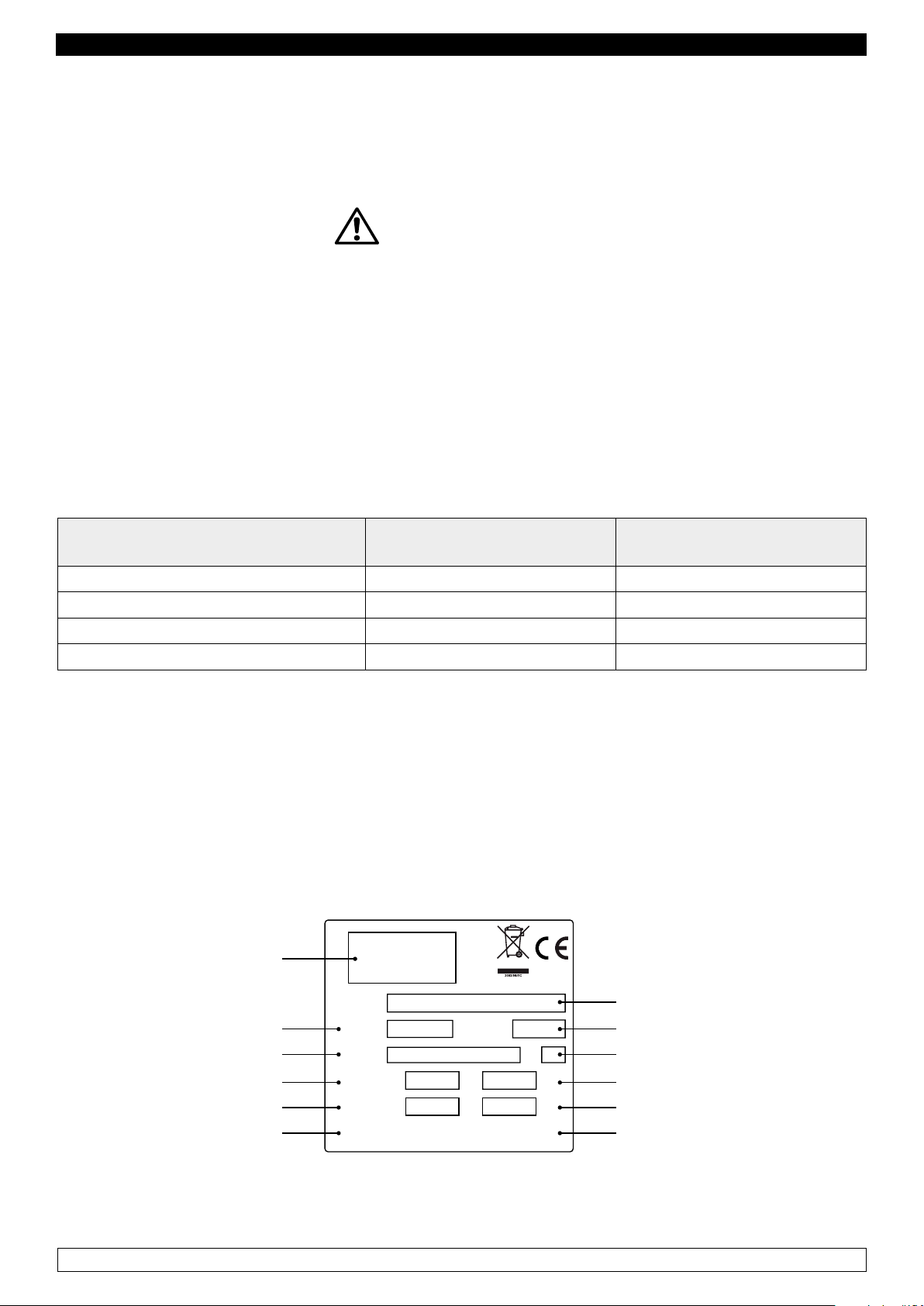
The data are reported on the EC label placed on the blast chiller. For the models KING TROLLEY 20 at
the upper back, for the models KING TROLLEY 40-80-120 sidewards of the instrument panel.
Manufacturing Company
Code article
Operating voltage
Power consumption
Cooling capacity
Type of coolant
Modello
Model
Cod.Art
Code
Tensione
Tension
Assorbimento
Absorption
Gas
Gaz
Matricola
Ser. Number
A
CL.
Kw
Kg
Model
Registration Number
Climate class
Electrical power
Compressor power
Quantity of coolant
The manufacturer declines any liability for improper use of the blast chiller, as well as use that could not
have been reasonably foreseen, and for all operations performed on it that disregard the instructions in
the manual.
1
Page 3
ENGLISH
ATTENTION: The main general safety standards are listed below:
- Do not use or place electrical devices inside the refrigerated compartments if they are not of the
type recommended by the manufacturer
- Do not touch the blast chiller with damp or wet hands or feet
- Do not use the blast chiller barefoot
- Do not insert screwdrivers or other objects between the guards or moving parts
- Do not pull the power cord to unplug the blast chiller from the electricity network
- the blast chiller Is not intended to be used by persons (including children) with physical or mental
problems, or lack of experience and knowledge, unless they are controlled or instructed in using the
unit by a person responsible for their safety. Children must be supervised to ensure that they do not
play with the appliance.
- before carrying out any cleaning or maintenance, disconnect the blast chiller from the mains power
supply by turning off the main switch and pulling the plug
- in the event of failure and/or malfunction of the blast chiller, turn it off and to refrain from any attempt
to repair or intervene directly. It is necessary to exclusively contact a qualified technician.
The blast chiller is composed of a modular monocoque coated with different materials and insulated
with polyurethane foam of density 42 kg/m3.
In the design and construction, all measures have been adopted to ensure a blast chiller that complies
with safety and hygiene requirements, such as: rounded interior corners, deep drawing with drain on
the outside for the condensate liquids, no rough surfaces, fixed guards on moving or dangerous parts.
The products must be stored in observance of the load limits given in the table, in order to ensure
an efficient circulation of air inside the blast chiller.
Load capacity
KING TROLLEY 20 L 1 / P 1
KING TROLLEY 40 L 1 / P 1
KING TROLLEY 40 L 2 / P 2
KING TROLLEY 80 L 1 / P 1
KING TROLLEY 80 L 2 / P 2
2 x 20 GN 1/1
1 x 20 GN 2/1
2 x 20 GN 1/1
1 x 20 GN 2/1
3 x 20 GN 1/1
2 x 20 GN 2/1
5 x 20 GN 1/1
3 x 20 GN 2/1
5 x 20 GN 1/1
3 x 20 GN 2/1
1 x 20 EN 60x40
1 x 20 EN 60x80
2 x 20 EN 60x40
1 x 20 EN 60x80
2 x 20 EN 60x40
1 x 20 EN 60x80
4 x 20 EN 60x40
2 x 20 EN 60x80
4 x 20 EN 60x40
2 x 20 EN 60x80
KING TROLLEY 120 L 1 / P 1
KING TROLLEY 120 L 2 / P 2
The installation must be performed exclusively by a qualified technician
8 x 20 GN 1/1
5 x 20 GN 2/1
8 x 20 GN 1/1
5 x 20 GN 2/1
2
7 x 20 EN 60x40
4 x 20 EN 60x80
7 x 20 EN 60x40
4 x 20 EN 60x80
Page 4
ENGLISH
A
L
C
O
O
L
1.1 It is prohibited to remove the guards and safety devices
t is absolutely forbidden to remove safety guards.
The manufacturer disclaims any liability for accidents due to failure to comply with this obligation.
1.2 Information on emergency operations in the event of fire
- disconnect the blast chiller from the electrical outlet or cut off the main power supply
- do not use water jets
- use dry chemical or CO2 extinguishers
CHAPTER 2 CLEANING THE REFRIGERATOR
Since the blast chiller will be used to store food, cleaning is necessary for hygiene and health
protection purposes. The cleaning of the blast chiller has already been carried out at the factory. It
is suggested, however, to carry out an additional cleaning of the internal parts before use, making
sure that the power cord is unplugged.
2.1 Cleaning the interior and exterior cabinet
For this purpose the following are indicated
- the cleaning products: water and mild, non-abrasive detergents. DO NOT USE SOLVENTS AND
THINNERS
- methods for cleaning: wash the interior and exterior parts with warm water and mild soap or with a
cloth or sponge with suitable products
- disinfection: avoid substances that can alter the organoleptic characteristics of the food
- rinsing: cloth or sponge soaked in warm water. DO NOT USE WATER JETS
- frequency: weekly is recommended, the user can set different frequencies depending on the type
of food being stored.
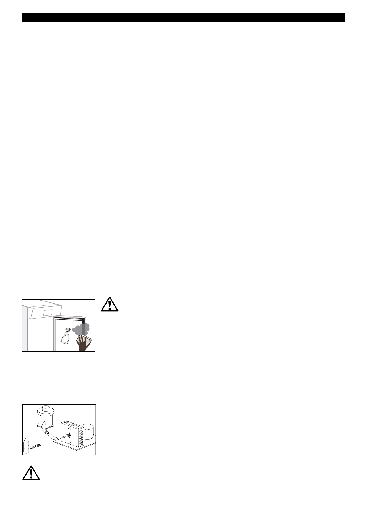
REMARK : Clean frequently the door seals.
Some preserved products could release some enzymes that could damage
the seals causing its quick deterioration.
For the cleaning, use only specific products for this purposes, available also
on request on our sales network.
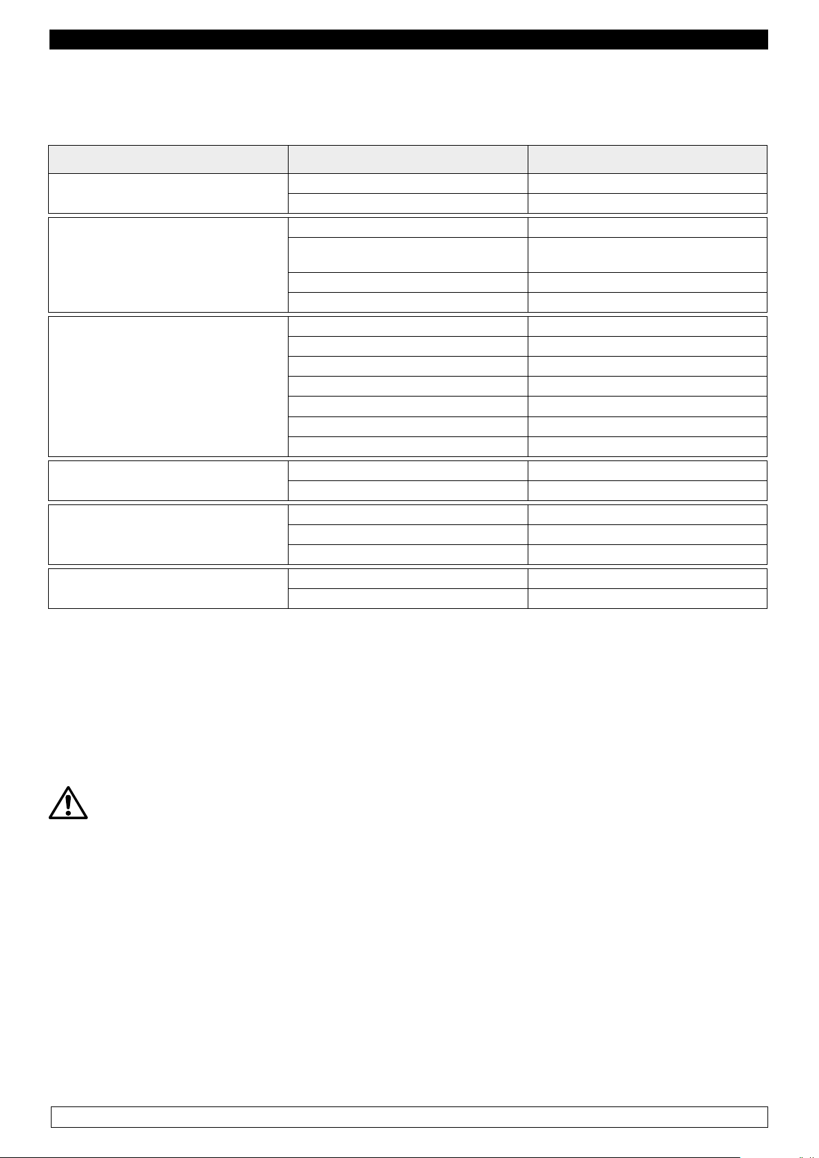
2.2 Cleaning the condenser
The efficiency of
necessary to clean it on a monthly basis. Before carrying out this operation, switch off
the blast chiller
is compromised by the clogging of the condenser, therefore it is
the blast chiller
unplug the power cord and proceed as follows:
Fig.1
Remote motocondensing unit
With the aid of a jet of air or dry brush, eliminate, in a vertical movement (Fig.
1), the dust and lint deposited on the fins. In the case of greasy deposits, we
recommend using a brush moistened with special cleaning agents.
During this operation, use the following personal protective equipment: goggles, respiratory
protection mask, chemically resistant gloves (gasoline-alcohol).
3
Page 5

ENGLISH
CHAPTER 3 PERIODIC CHECKS TO BE CARRIED OUT
The following are the points or units of the blast chiller that require periodic checks:
- integrity and efficiency of door seals
- integrity of the grilles in contact with food
- integrity of the fixing hinges of the doors
- integrity of the power cord of the blast chiller and the remote motocondensing unit
3.1 PRECAUTIONS IN CASE OF LONG PERIODS OF INACTIVITY
A long period of inactivity is defined as a stoppage of more than 15 days.
It is necessary to proceed as follows:
- switch off the blast chiller and the remote motocondensing unit and disconnect it from the power
supply
- carry out a thorough cleaning of the interior cabinet, shelves, trays, guides and supports, paying
special attention to critical points such as the joints and magnetic gaskets, as indicated in Chapter 2.
- leave the door partly open to prevent air stagnation and residual humidity
CHAPTER 4 PREVENTIVE MAINTENANCE
4.1 Restarting after a long period of inactivity
Restarting after long inactivity is an event that requires preventive maintenance.
It is necessary to perform a thorough cleaning as described in chapter 2.
4.2 Control of the warning and control devices
We recommend that you contact your dealer for a service or maintenance contract that includes:
- cleaning of the condenser of the blast chiller and the remote motocondensing unit
- verification of the coolant load
- verification of the full cycle operation
- electrical safety
CHAPTER 5 EXTRAORDINARY MAINTENANCE AND REPAIR
All maintenance activities that have not been described in previous chapters are considered
“Extraordinary Maintenance.” Extraordinary maintenance and repair are tasks reserved exclusively
to the specialist personnel authorized by the manufacturer.
No liability is accepted for actions carried out by the user, by unauthorized personnel, or with the use
of non-original replacement parts.
4
Page 6
ENGLISH
CHAPTER 6 TROUBLESHOOTING
Problems may occur, in the blast chiller, identified as shown in the table:
TROUBLE DESCRIPTION POSSIBLE CAUSES HOW TO REPAIR IT
the blast chiller does not turn on no power supply check the plug, socket, fuses, line
other fuses, line
the refrigeration unit does not start the set temperature has been reached set new temperature
defrosting in progress
control panel failed contact technical support
other contact technical support
wait until the end of cycle / turn power off
and on again
the refrigeration unit runs continuously but does not reach the set
temperature
the refrigeration unit does not stop at
the set temperature
block of ice on the evaporator
accumulation of water or ice in the
drip tray
location is too hot aerate more
condenser is dirty clean the condenser
insufficient coolant contact technical support
stop the condenser fan contact technical support
insufficient sealing of doors check the seals / provision of goods
evaporator completely frosted manual defrosting
other contact technical support
command panel failed contact technical support
P1 temperature sensor failed contact technical support
misuse see chapter 1.
defrost heater fault contact technical support
defrost probe P2 damaged contact technical support
drain clogged clean the pipette and the drain
blast chiller is not level check levelling
CHAPTER 7 INSTRUCTIONS FOR REQUESTING ASSISTANCE
For any technical problem, and any requests for assistance or service, you must exclusively contact
your own dealer with the code and the registration number described on the label of technical data
applied on the equipment
CHAPTER 8 SAFETY AND ACCIDENT PREVENTION
ATTENTION: The blast chiller has been built with suitable measures to ensure the safety and
health of the user.
The following are the measures taken to protect against mechanical risks:
- stability: The blast chiller, even with the grilles removed, has been designed and built in such a way
that under the intended operating conditions, its stability is suitable for use without risk of overturning,
falling or unexpected movement
- surfaces, edges, corners: the accessible parts of the blast chiller are, within the limits allowed by
their functions, free of sharp angles and sharp edges, as well as rough surfaces likely to cause injury
- moving parts: were designed, constructed and arranged to avoid risks. Certain parts are equipped
with fixed guards so as to prevent risks of contact which may result in injury.
5
Page 7
ENGLISH
The following are the measures taken to protect against other risks:
- electricity: The blast chiller has been designed, built and equipped so as to prevent risks from
electricity, in accordance with the specific legislation in force
- noise: The blast chiller has been designed and built in such a way that risks resulting from the
emission of airborne noise are reduced to the minimum level
8.1 safety devices adopted
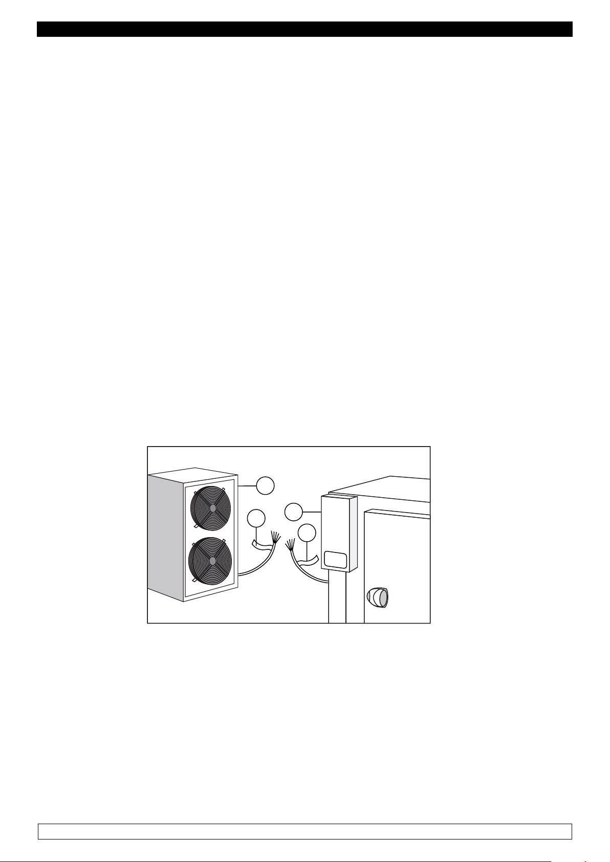
It is absolutely forbidden (Fig. 2) :
- to tamper with or remove the closing panels of the monocondensing unit
- remove the labels applied describing the technical characteristics (1) and the warnings for grounding
of the blast chiller
- remove the labels applied describing the technical characteristics and the warnings for grounding
of the motocondensing unit
- remove the label of the blast chiller which warns the user to turn off the power supply before working
on the unit
- remove the label of the remote motocondensing unit which warns the user to turn off the power
supply before working on the unit
- to remove the labels applied on the blast chiller indicating grounding
- to remove the labels applied on the remote motocondensing unit indicating grounding
- to remove the label applied on the power cord, indicating the type of power supply (2)
The manufacturer declines any responsibility for the safety of the blast chiller if this were to happen.
1
2
1
2
Fig.2
8.2 Indications for optimal operation
- do not block the air vents of the remote motocondensing unit
- place the foodstuffs on the appropriate shelves or containers. Do not place them directly on the
bottom, or leaning against the walls, doors or fixed guards
- close the doors carefully
- always keep the defrost water drain hole clear of obstructions
- limit, to the extent possible, the frequency and duration of door opening. Each opening causes a
change in the internal temperature
- perform periodically current maintenance (see chapter 3)
6
Page 8
ENGLISH
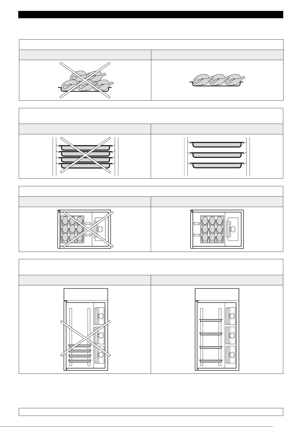
Right load of the blast chiller
Avoid overloading the blast chiller beyond the set limits shown in the table
NO OK
Do not place the trays too close to each other so as to avoid uneven air circulation inside the blast
chiller
NO OK
Do not place the trays too far away from the evaporator
NO OK
Do not concentrate the trays in one area of the blast chiller in case the load is not complete; distribute
its height evenly
NO OK
In case of interruption or failure of the power supply circuit, prevent the opening of the doors in order
to maintain a uniform temperature inside the blast chiller. If the problem persists longer than a few
hours it is recommended to move the material to a suitable place.
7
Page 9
ENGLISH
7
8
12345
6
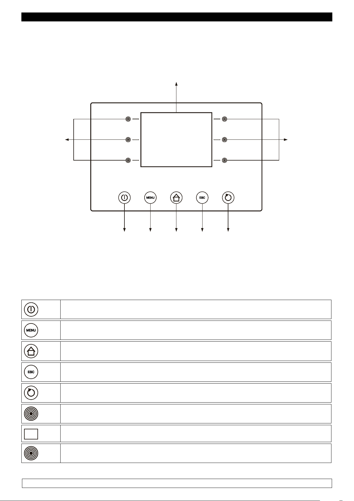
CHAPTER 9 CONTROLS
9.1 Description of the controls and buttons (Fig. 3)
Fig.3
The control buttons with which the blast chiller is equipped are:
1
2
3
4
5
6
On / off push-button, “ON / OFF”
Option push-button, “MENÙ push-button”
Preset push-button, “HOME push-button”
Cancel push-button, “ESC push-button”
START/STOP push-button , “START / STOP push-button”
Interactive push-button
7
8
Display
Interactive push-button
8
Page 10
ENGLISH
9.2 INSTRUCTIONS FOR USE
9.2.1 Starting
Before starting the temperature blast chiller you need to check if electrical and power connections
have been carried out according to what stated at Chapter 17.
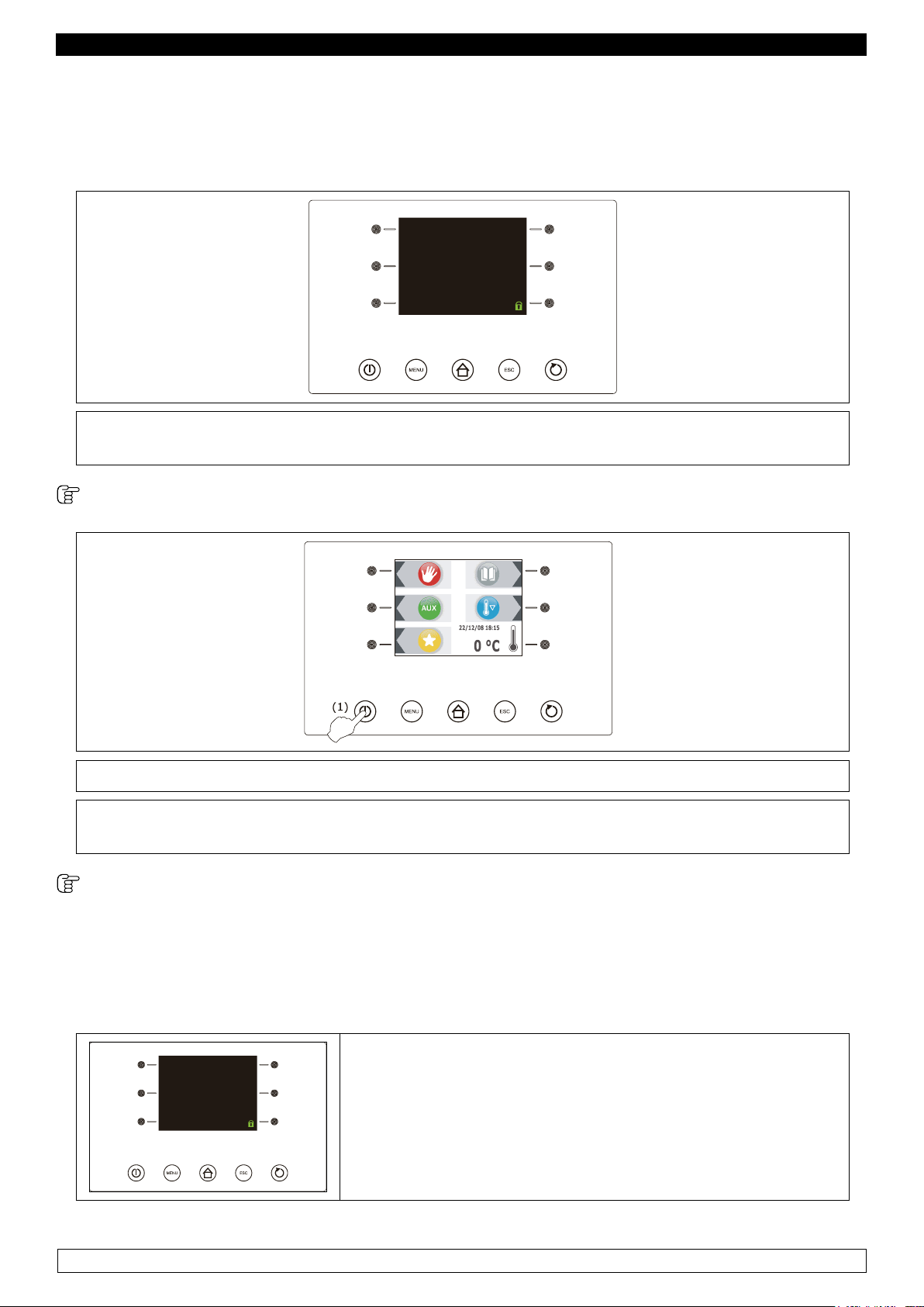
LOADING...
► Connect the machine to power supply: the display is turned off for 10 seconds then it will
show the “OFF” mode.
With card in OFF mode:
► Press and release the ON / STAND-BY key (1).
► Should the power supply failure cause the clock error (code “rtc”) you need to set date and
time again, see paragraph “9.2.2 Internal clock setting: set date and present time”.
Control panel switching On/Off :
Proceed as follows:
- Make sure the keyboard is not locked and no procedure is currently under process.
- Press and release the ON / STAND-BY key (1).
► In the “OFF” mode the control panel is turned off.
9
Page 11
Program: MANUAL
Elapsed time: 90 min
Program: MANUAL
Elapsed time: 90 min
ENGLISH
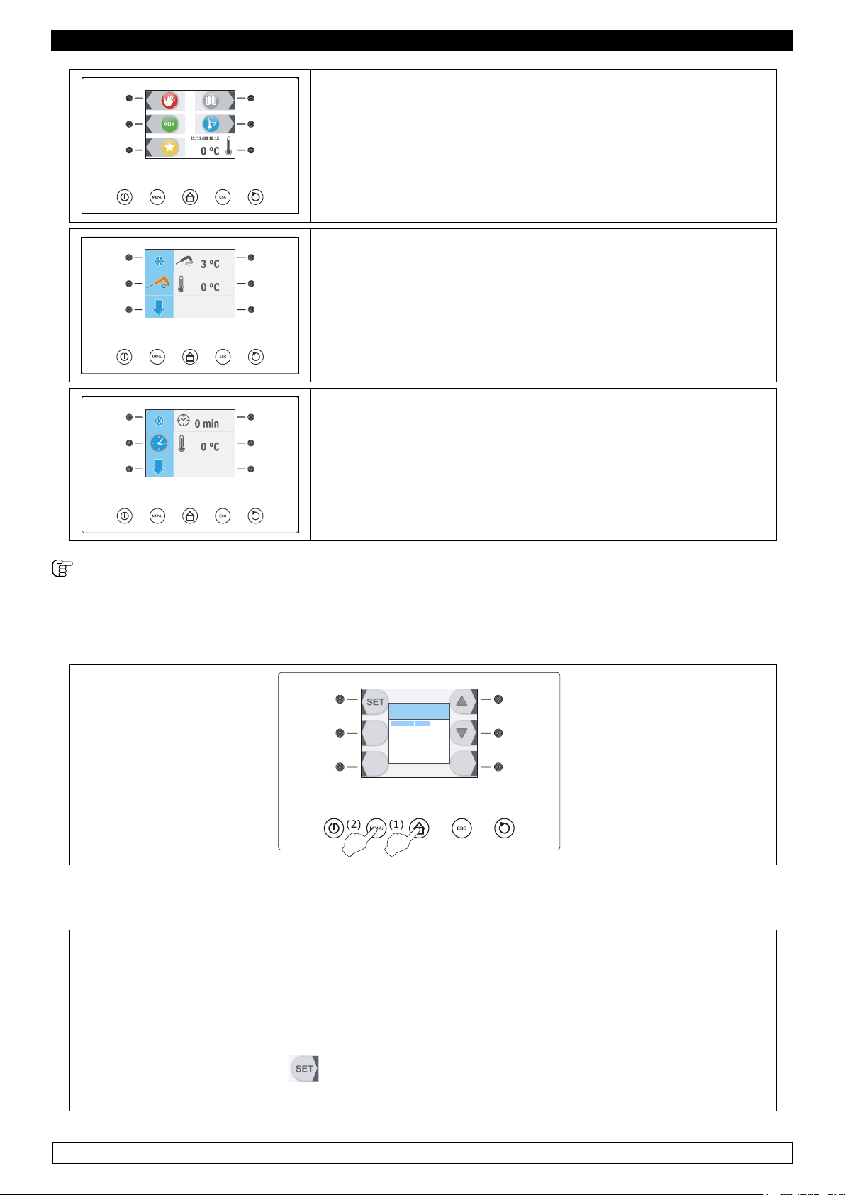
► In the “ON” and “STAND-BY” modes the control panel will
show date, real time and cell temperature.
► In the “RUN” mode the display will show what follows:
- if a temperature cooling or freezing process is currently under process, the temperature taken by the core probe, the cell
temperature, the name of the program (if any) and the time
elapsed since the starting of the cooling or freezing process.
► If a time cooling or freezing process is currently under pro-
cess, the remaining time of cooling and freezing process, the
cell temperature, the name of the program (if any) and the
time elapsed since the starting of the cooling or freezing process.
9.2.2 Internal Clock setting: Set date and present time (fig.3)
First set the internal clock at present time proceeding as follows:
OPTIONS
22/12/08 18:15
HACCP ALARMS
PARAMETERS
LANGUAGE
INTERNAL VALUES
LIST ALARMS
- Make sure the control panel is switched in the “ON” mode.
- Make sure the keyboard is not locked and no procedure is currently under process.
► Press and release the HOME key (1),
► Press and release the MENU key (2), then
► Select the first item of the “CURRENT DATE AND TIME” menu.
► Press and release the key to enter the adjustment menu
10
Page 12
ENGLISH
To set current date proceed as follows:
22/12/08
18:15
► Press and release the key or the key to modify the day.
► Press and release the key to conrm the data entered,
► Once the date has been set, the control panel will automatically set current year, hours and
minutes.
► Press and release the key or the key to modify the data entered.
► Press and release the key to conrm the data entered,
Press and release the ESC key to exit from the above procedure or do not work for 60 seconds.
9.2.3 Language setting (fig.3)
Proceed as follows:
OPTIONS
22/12/08 18:15
HACCP ALARMS
PARAMETERS
LANGUAGE
INTERNAL VALUES
ALARMS LIST
- Make sure the control panel is switched in the “ON” mode.
- Make sure the keyboard is not locked and no procedure is currently under process.
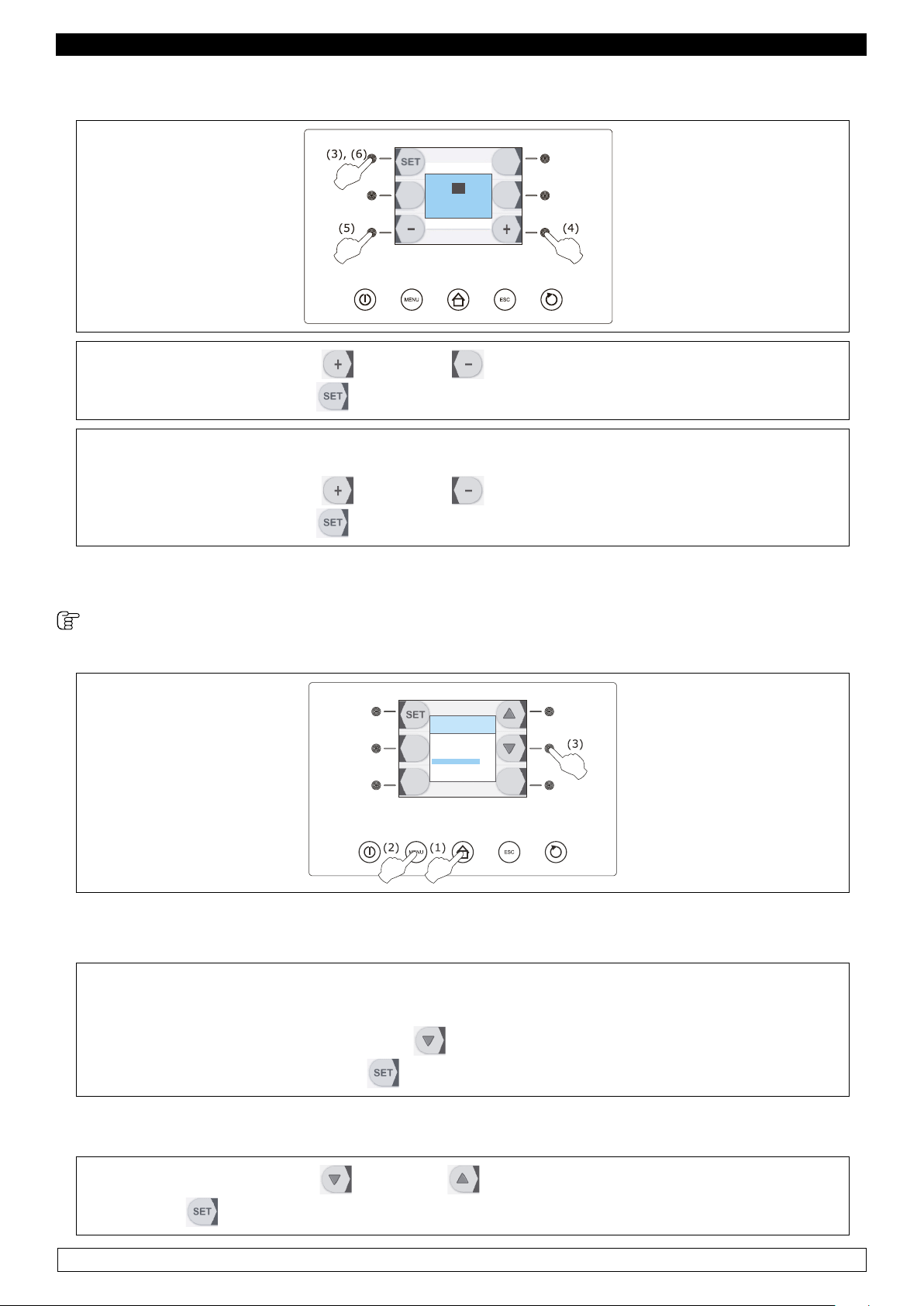
► Press and release the HOME key (1),
► Press and release the MENU key (2),
► Press and release repeatedly the key (3) and select “LANGUAGE”.
► Press and release the key again .
To select a language proceed as follows:
► Press and release the key or the key to select the language, then press and rele-
ase the key
again to conrm.
11
Page 13

ENGLISH
Press and release the ESC key to exit from the above procedure.
9.2.4 Operation
The temperature blast chiller is able to manage the following types of operating cycles:
► Positive Temperature Cooling with core probe (Par. 9.2.5)
► Hard Positive Temperature Cooling with core probe (Par. 9.2.6)
► Time Positive Temperature Cooling (Par. 9.2.7)
► Time Hard Positive Temperature Cooling (Par. 9.2.8)
► Soft Positive Temperature continuous cooling (Par. 9.2.9)
► Freezing with core probe (Par. 9.2.10)
► Soft Freezing with core probe (Par. 9.2.11)
► Time Freezing (Par. 9.2.12)
► Time Soft Freezing (Par. 9.2.13)
► Continuous Hard Freezing (Par. 9.2.14)
► Precooling (Par. 9.2.15)
► Fish Sanitization Process (Par. 9.2.18)
We suggest you to carry out the cell precooling process before each and every operating cycle; see
paragraph “9.2.15 Precooling”.
The temperature operating cycles are preceeded by a test to verify if the core probe has been inserted properly; see paragraph “9.2.16 Test for checking the core probe proper insertion”.
At the end of every operating cycle the system will automatically switch to the preservation phase,
except for the continuous cooling and freezing cycles.
It is also possible to perform the following functions:
► Switching-on of the UV- light used to sterilize the cell (optional) (Par. 9.2.17)
See following paragraphs for further information
Plase note: All cooling cycles are pre-set on Soft mode by default so the Hard mode needs
to be selected.
Please note: all the Freezing cycles are pre-set on Hard mode by default so the Soft mode
needs to be selected .
Please note : the Continuous Cooling and Freezing Mode refers to cycles having an unlimi-
ted duration.
12
Page 14
ENGLISH
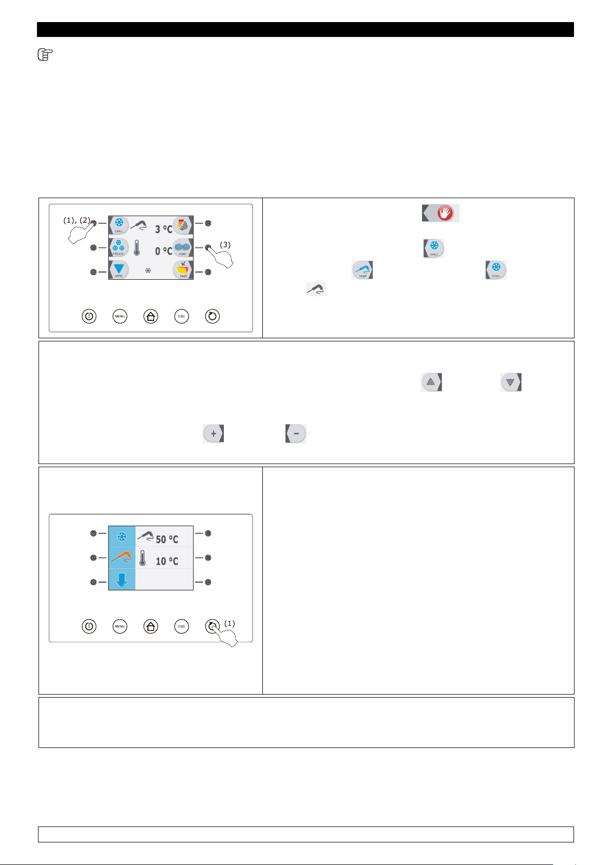
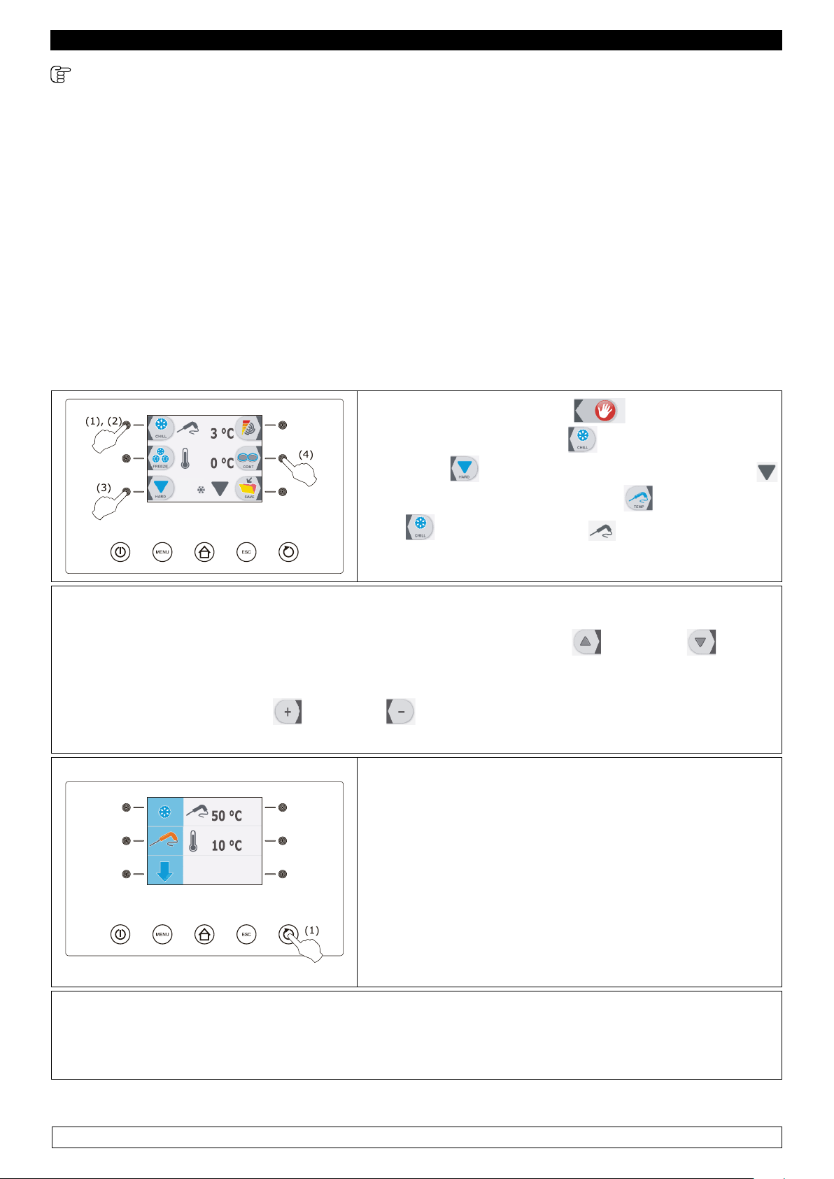
9.2.5 Positive Temperature Cooling with core probe
TheTemperature Cooling and preservation cycle consists of the following two phases:
► Cooling
► Preservation
When a phase is over the control panel automatically switches to the next step.
To start a cycle proceed as follows:
► Press and release the key (1),
► Press and release the key (2), then press and re-
lease the key
(3): until the icon is lit on the
screen
The display will show the end-of-cooling temperature and the running temperature during the cooling phase.
► Press and release the key MENÙ, then press and release the key or the key to select
the end-of-cooling temperature and the running value during the cooling phase, other than the set
ones.
► Press and release the key or the key to change these values then press the ESC key
to store them.
► Press and release the START / STOP key (1): the test
to verify if the core probe has been inserted properly will
start; see paragraph “Test for checking the core probe
proper insertion”.
► If the test is completely successful, the cycle starts.
Program: MANUAL
Elapsed time: 0 min
► The count of the cooling maximum duration will start
only if the temperature taken by the core probe is lower
than the set temperature.
► If the test is not successfully completed the buzzer will
sound for 5 seconds every 60 seconds and a time cycle
will start; see paragraph “Time cooling and preservation”.
During the cooling phase the display will show the temperature taken by the core probe, the cell
temperature, the name of the program (if any) and the time elapsed since the starting of the cooling
process.
► To stop the cycle proceed as follows : hold the START / STOP key pressed for 3 seconds.
13
Page 15
ENGLISH
► If the temperature taken by the core probe reaches the end-of-cooling temperature within the coo-
ling phase time limit , the cooling will be successfully completed, the control panel will automatically
switch to the preservation phase and the buzzer will sound.
To silence buzzer press and release any key.
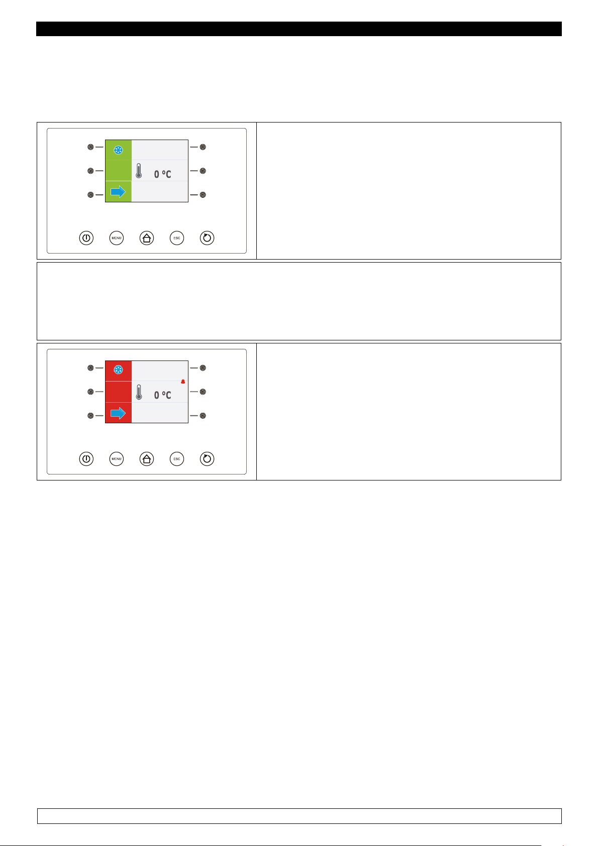
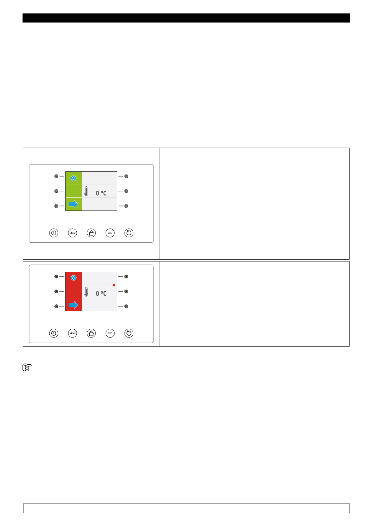
► During the preservation phase the display will show
End
Program: MANUAL
Cycle time: 70 min
► If the temperature taken by the core probe does not reach the end-of-cooling temperature within
the cooling phase time limit, the cooling process will not be successfully completed but it will go on
working and the buzzer will sound.
the cell temperature, the name of the program (if any)
and the time taken to complete the cooling phase successfully.
►
To restore the normal display and to silence buzzer press and release any key.
► When the temperature taken by the core probe rea-
End
ches the end-of-cooling temperature , the control panel
will automatically switch to the preservation phase as
Program: MANUAL
Cycle time: 100 min
stated above.
14
Page 16
ENGLISH
9.2.6 Hard Positive Temperature cooling with core probe
The temperature hard cooling and preservation cycle consists of the following three phases:
► Cooling hard phase
► Cooling
► Preservation
When a phase is over the control panel automatically switches to the next step.
To start the cycle proceed as follows:
- Make sure the display is in the “ON” mode.
- Make sure the keyboard is not locked and no procedure is currently under process.
► Press and release the key (1),
► press and release the key (2), then press and rele-
ase the key
and nally press and release the
icon
is lit on the screen.
(3) so the display will show the icon
(4): key until the
IThe display will show the end-of-cooling temperature and the running temperature during the cooling phase.
► Press and release the MENU key, then press and release the key or the key key to
select the end-of-cooling temperature and the operating value during the cooling phase, other than
the set ones.
► Press and release the key or the key to change these values then press the ESC key
to store them.
► Press and release the START / STOP key (1): the test
to verify if the core probe has been inserted properly will
start; see paragraph “Test for checking the core probe
proper insertion”.
Program: MANUAL
Elapsed time: 0 min
► If the test is completely successful, the cycle starts.
The count of the cooling time limit will start only if the
temperature taken by the core probe is lower than the
fixed temperature.
► If the test is not successfully completed the buzzer will sound for 5 seconds every 60 seconds
and a time cycle will start; see paragraph “Time hard cooling and preservation”. During the cooling
hard phase the display will show the temperature taken by the core probe, the cell temperature,
the name of the program (if any) and the time elapsed since the starting of the cooling process.
► Hold the START / STOP key pressed for 3 seconds to stop the cycle.
15
Page 17
ENGLISH
When the temperature taken by the core probe reaches the end-of-hard-cooling phase the control
panel will automatically switch to the cooling phase.
During the cooling phase, the display will show the temperature taken by the core probe, the cell
temperature, the name of the program (if any) and the time elapsed since the starting of the cooling
process.
► If the temperature taken by the core probe reaches the end-of-cooling temperature within the co-
oling phase time limit , the cooling will be completely successful, the control panel will automatically
switch to the preservation phase and the buzzer will sound.
► To silence buzzer press and release any key.
► During preservation the display will show the cell tem-
perature, the name of the program (if any) and the time
taken to complete the cooling phase successfully.
End
► If the temperature taken by the core probe does not
Program: MANUAL
Cycle time: 70 min
reach the end-of-cooling temperature within the cooling
phase time limit , the cooling will not be successfully completed but it will go on working and the buzzer will sound.
► To restore the normal display and to silence buzzer
press and release any key.
► When the temperature taken by the core probe rea-
End
ches the end-of-cooling temperature , the control panel
will automatically switch to the preservation phase as
Program: MANUAL
Cycle time: 100 min
stated above.
9.2.7 Time Positive Temperature Cooling
Time cooling and preservation cycle consists of the following two phases:
► Cooling
► Preservation
When a phase is over the control panel automatically switches to the next step.
To start the cycle proceed as follows:
- Make sure the display is in the “ON” mode.
- Make sure the keyboard is not locked and no procedure is currently under process.
16
Page 18

ENGLISH
► Press and release the key (1), then press and
release the key
(2):
The display will show the cooling duration and the running temperature during the cooling process
► Press and release the MENU key, then press and release key or the key key to select
the duration of the cooling phase and the running temperature during the cooling process , other
than the set one.
► Press or release the key or the key to modify these values then press the ESC key to
store them.
► Press and release the START / STOP key (1) : the
cycle will start.
Program: MANUAL
Elapsed time: 0 min
During the cooling phase, the display will show the remaining time of the cooling phase, the cell temperature,
the name of the program (if any) and the time elapsed
since the starting of the cooling process.
►
Hold the START/STOP key pressed for 3 seconds to stop the cycle.
When the cooling phase is over the control panel will automatically switch to the preservation phase
and the buzzer will sound.
► To silence buzzer press and release any key.
► During preservation the display will show the cell tem-
End
perature, the name of the program (if any) and the cooling time.
Program: MANUAL
Cycle time: 90 min
9.2.8 Time Hard Positive Temperature Cooling
The time hard coolingand conservation cycle consists of the following three phases:
► Cooling hard phase
► Cooling
► Preservation.
17
Page 19

ENGLISH
When a phase is over the control panel automatically switches to the next step.
To start the cycle proceed as follows:
► Make sure the display is in the “ON” mode.
►Make sure the keyboard is not locked and no procedu-
re is currently under process.
► Press and release the key (1), press and rele-
ase the key
(2), than press and release the key
(3): in order the displaymodo che sul display compaia il
simbolo
The display will show the duration of the cooling phase and the running temperature during the cooling
process.
► Press and release the MENU key, then press and release the key
or the key to select the
duration of the cooling phase and the running temperature during the cooling process, other than
the set one.
► Press and release the key or the key to modify these values then press the ESC key to
store them.
► Press and release the START / STOP key (1) : the
cycle will start.
► During the hard cooling phase, the display will show
Program: MANUAL
Elapsed time: 0 min
the remaining time of the cooling phase, the cell temperature, the name of the program (if any) and the time
elapsed since the starting of the cooling process.
► Hold the START/STOP key pressed for 3 seconds to
stop the cycle.
► When the hard cooling phase is over the control panel will automatically switch to the cooling
phase.
► During the cooling phase the display will show the remaining time of the cooling phase , the cell
temperture, the name of the program (if any) and the time elapsed since the starting of the cooling
process.
► When the cooling phase is over the control panel will automatically switch to the preservation
phase and the buzzer will sound. To silence buzzer press and release any key.
► During the preservation phase the display will show the
End
cell temperture, the name of the program (if any) and the
cooling process duration.
Program: MANUAL
Cycle time: 90 min
18
Page 20

ENGLISH
9.2.9 Positive Temperature Continuous Cooling
To start the cycle proceed as follows:
► Make sure the display is in the “ON” mode.
►Make sure the keyboard is not locked and no procedu-
re is currently under process.
► Press and release the (1) key, press and re-
lease the
(2) key, then press and release twice the
(3) key: until the icon appears on the display.
The display will show the running temperature during the cooling process.
► Press and release the MENU key, then press and release the key or the key to select
the running temperature during the cooling process, other than the set one.
► Press and release the key or the key to modify this value then press the ESC key to
store it.
► Press and release the START / STOP (1) key: the cycle
will start.
During the cooling phase, the display will show the cell
Program: MANUAL
Elapsed time: 0 min
temperature, the name of the program (if any) and the
time elapsed since the starting of the cooling process.
► Hold the START/STOP key pressed for 3 seconds to
stop the cycle.
19
Page 21

ENGLISH
9.2.10 Freezing with core probe
The temperature freezing and preservation cycle consists of the following two phases:
► Freezing
► Preservation.
When a phase is over the control panel automatically switches to the next step.
To start the cycle proceed as follows:
► Make sure the display is in the “ON” mode.
►Make sure the keyboard is not locked and no procedu-
re is currently under process.
► Press and release the
ase the
(2) key, then press and release the (3)
(1) key, press and rele-
key in order the icon appears on the display
and nally press and release the
icon
“core probe” disappears.
(4) key: in order the
The display will show the end-of-freezing temperature and the running temperature during the
freezing process.
► Press and release the MENU key , then press and release the key or the key to select
the end-of-freezing temperature and the operating setpoint during the freezing process, other than
the set ones.
► Press and release the key or the key to mo-
dify these values then the ESC key to store them.
► Press and release the START / STOP key (1) : the test
to verify if the core probe has been inserted properly will
Program: MANUAL
Elapsed time: 0 min
start; see paragraph “Test for checking the core probe
proper insertion”.
► If the test is completely successful, the cycle starts.
► If the test is not successfully completed the buzzer will
sound for 5 seconds every 60 seconds and a time cycle
will start; see paragraph “Time freezing and preservation”.
20
Page 22

ENGLISH
► During the freezing process the display will show the temperature taken by the core probe, the
cell temperature, the name of the program (if any) and the time elapsed since the starting of freezing process.
► Hold the START/STOP key pressed for 3 seconds to stop the cycle.
► If the temperature taken by the core probe reaches the end-of-freezing temperature wihin the
freezing phase time limit , the freezing will be successfully completed, the control panel will automatically switch to the preservation phase and the buzzer will sound.
► To silence buzzer press and release any key.
► During the preservation phase the display will show the
End
Program: MANUAL
Cycle time: 220 min
cell temperature, the name of the program (if any) and
the time taken to complete freezing successfully.
► If the temperature taken by the core probe does not reach the end-of-freezing temperature within
the freezing phase time limit, the freezing will not be successfully completed but it will go on working and the buzzer will sound.
► To restore the normal display and silence buzzer press and release any key.
► When the temperature taken by the core probe rea-
End
ches the end-of-freezing temperature, the control panel
automaticaly switches to the preservation phase as sta-
Program: MANUAL
Cycle time: 220 min
ted before.
9.2.11 Soft Freezing with core probe
The Temperature soft freezing and preservation cycle consists of the following three phases:
► Freezing soft phase
► Freezing
► Preservation.
When a phase is over the control panel automatically switches to the next step.
To start the cycle proceed as follows:
21
Page 23

ENGLISH
► Make sure the display is in the “ON” mode.
►Make sure the keyboard is not locked and no procedu-
re is currently under process.
► Press and release the
ase
oder the icon
(2) key, then press and release (3) key : in
“core probe” disappears.
(1) key, press and rele-
The display will show the end-of-freezing temperature and the running temperature during the
freezing process
► Press and release the MENU key, then press and release the key or the key, key to
select the end-of-freezing temperature and the operating setpoint during the freezing process,
other than the set ones.
► Press and release the key or the key to modify these values, then the ESC key to store
them;
► Press and release the START / STOP key (1): the test
to verify if the core probe has been inserted properly will
start; see paragraph “Test for checking the core probe
proper insertion”.
► If the test is completely successful, the cycle starts.
Program: MANUAL
Elapsed time: 0 min
► If the test is not successfully completed the buzzer
will sound for 5 seconds every 60 seconds and a time
cycle will start; see paragraph “Time soft freezing and
preservation”.
► During the freezing soft phase the display will show
the temperature taken by the core probe, the cell temperature, the name of the program (if any) and the time
elapsed since the starting of the freezing process
.
► Hold the START/STOP key pressed for 3 seconds to stop the cycle.
► When the temperature taken by the core probe reaches the end-of-soft-freezing phase, the
control panel will automatically switch to the freezing phase.
► During the freezing phase the display will show the temperature taken by the core probe, the
cell temperature, the name of the program (if any) and the time elapsed since the starting of the
freezing process.
► If the temperature taken by the core probe reaches the end-of-freezing temperature within the
freezing phase time limit , the freezing will be successfully completed, the control panel will automatically switch to the preservation phase and the buzzer will sound.
► To silence buzzer press and release any key.
22
Page 24

ENGLISH
► During the preservation phase the display will show
End
Program: MANUAL
Cycle time: 220 min
► If the temperature taken by the core probe does not reach the end-of-freezing temperature
within the freezing phase time limit , the freezing will not be successfully completed but it will go
on working and the buzzer will sound.
► To restore the normal display and silence buzzer press and release any key
End
Program: MANUAL
Cycle time: 250 min
the cell temperature, the name of the program (if any)
and the time taken to complete the freezing successfully.
► When the temperature taken by the core probe rea-
ches the end-of-freezing temperature, the control panel
automaticaly switches to the preservation phase as stated before.
9.2.12 Time Freezing
The Time Freezing and preservation cycle consists of the following two phases:
► Freezing
► Preservation
When a phase is over the control panel automatically switches to the next step.
To start the cycle proceed as follows:
► Make sure the display is in the “ON” mode.
► Make sure the keyboard is not locked and no procedu-
re is currently under process.
► Press and release the (1) key, press and relea-
se
(2) key, then press and release (3) key : in
order the icon HARD will appear on the display.
23
Page 25

ENGLISH
The display will show the duration of the freezing phase and the running setpoint during the freezing process.
► Press and release the MENU key, then press and release the key or the key key to
select the duration of the freezing phase running setpoint during the freezing process, other than
the set one.
► Press and release the key or the key to modify these values, then the ESC key to store
them.
► Press and release the START / STOP (1) key: the cycle
will start.
► During freezing the display will show the remaining
Program: MANUAL
Elapsed time: 0 min
time of freezing, the cell temperature, the name of the
program (if any) and the time elapsed since the starting
of the freezing process.
►
Hold the START/STOP key pressed for 3 seconds to stop the cycle.
► When the freezig time is over the control panel will automatically switch to the preservation phase
and buzzer will sound.
► To silence buzzer press and release any key.
► During the freezing phase the display will show the cell
End
temperature, the name of the program (if any) and the
duration of the freezing process.
Program: MANUAL
Cycle time: 240 min
9.2.13 Time Soft Freezing
The Time Soft Freezing and preservation cycle consists of the following three phases:
► Freezing soft phase
► Freezing
► Preservation.
When a phase is over the control panel automatically switches to the next step.
To start the cycle proceed as follows:
24
Page 26

ENGLISH
► Make sure the display is in the “ON” mode.
► Make sure the keyboard is not locked and no procedu-
re is currently under process.
► Press and release the (1) key, then press
and release the
(2) key: the display will show the
duration of the freezing phase and the operating setpoint
during the freezing process.
► Press and release the MENU key, then press and release the key or the key to select
the duration of the freezing phase and the operating setpoint during the freezing process, other
than the set ones.
► Press and release the key or the key key to modify these values then the ESC key to
save them.
► Press and release the START / STOP key (1): the cycle
will start.
Program: MANUAL
Elapsed time: 0 min
► During the freezing soft phase the display will show
the remaining time of freezing , the cell temperature, the
name of the program (if any) and the time elapsed since
the starting of the freezing process.
► Hold the START/STOP key pressed for 3 seconds to stop the cycle.
► When the freezing soft phase time is over the control panel will automatically switch to the freezing pha-
se.
► During freezing the display will show the remaining time of the freezing process, the cell temperature, the
name of the program (if any) and the time elapsed since the starting of the freezing process.
► When the freezing time is over the control panel will automatically switch to the preservation phase and
buzzer will be sounding. To silence buzzer press and release any key.
.
► During the preservation phase the display will show the
End
cell temperature, the name of the program (if any) and
the duration of the freezing process.
Program: MANUAL
Cycle time: 240 min
25
Page 27

9.2.14 Continuous Hard Freezing
To start the cycle proceed as follows:
ENGLISH
► Make sure the display is in the “ON” mode.
► Make sure the keyboard is not locked and no procedu-
re is currently under process.
► Press and release the (1), press and release
the
(2) key, then press and release twice the (3)
key: until the icon is shown on the display.
► The display will show the operating setpoint during the
freezing process.
► Press and release the MENU key, then press and release the key or the key to select
the running temperature during the freezing process, other than the set one.
► Press and release the key or the key to modify this value then the ESC key to save it.
► Press and release the START / STOP key (1): the cycle
will start.
INF
► During the freezing process the display will show the
Program: MANUAL
Elapsed time: 0 min
cell temperature, the name of the program (if any) and
the time elapsed since the starting of the freezing process.
► Hold the START/STOP key pressed for 3 seconds to
stop the cycle.
9.2.15 Pre-cooling
Each running cycle can be preceeded by a precooling process.
To start the precooling cycle proceed as follows:
► Make sure the display is in the “ON” mode.
►Make sure the keyboard is not locked and no procedu-
re is currently under process.
► Press and release the (1) key, then press and
release the START / STOP key (2).
► Hold the START/STOP key pressed for 3 seconds to
stop the precooling cycle.
26
Page 28

ENGLISH
9.2.16 Test for checking the core probe proper insertion
Temperature cycles are preceeded by a two-phase test to check if the core probe has been properly
inserted.
The second phase will be carried out only if the rst one has not been successfully completed.
If the test has been successfully completed the cycle starts otherwise the buzzer will be sounding
for 5 seconds every 60 seconds and a time cycle will start.
► However to start a temperature cycle press the key or the key ; : after 1 minute since the
signal warns that test has not been successfully completed without operating a time cycle will start.
9.2.17 Switching-on of the UV light for the sterilization cycle (optional)
Proceed as follows:
► Make sure the display is in the “ON” mode and the door
is closed i.e. micro input port is not active.
► Make sure the keyboard is not locked and no procedu-
re is currently under process.
► Press and release the (1) key, press and relea-
se the
(2) key, , then press and release the START
/ STOP key (3);
The display will show the remaining time of the UV light switching on and the cell temperature.
► The UV light is switched on ; the opening of the door, i.e the micro input port is open , causes the
light switching off
9.2.18 Fish Sanification cycle
This Blast Chiller is provided with a specific program for raw fish sanification with adequate temperature and time. The Fish Sanification program consists of the following three phases:
► Temperature Freezing with core probe (core probe temperature -20°C)
► Holding time (core probe temperature -20°C duration: 24 hours)
► Preservation (cell temperature -22°C unlimited duration)
When a phase is over the system automatically switches to the next step.
To start the cycle proceed as follows:
27
Page 29

FISH SANIFICATION
ENGLISH
► Make sure the display is in the “ON” mode.
► Make sure the keyboard is not locked and no procedu-
re is currently under process.
► Press and release the (1) key, then press and
release
(2) key:
The display will show the end-of-cooling temperature , the running temperature during the cooling
process and the holding time.
► Press and release the key or the key to select these values and press and release
key
or the key to modify them.
► Press and release the START/STOP key (1): the test
to verify if the core probe has been inserted properly will
start; see paragraph “Test for checking the core probe
proper insertion”.
FISH SANIFICATION
Elapsed time: 0h
► If the test is successfully completed the cycle starts.
► If the test is not successfully completed , the buzzer
will be sounding, the display will show the “San ALARM”
signal and the cycle will be interrupted.
► To silence buzzer press and release any key.
► During the cooling process the display will show the temperature taken by the core probe, the cell
temperature and the time elapsed since the starting of the cooling phase.
► Hold the START/STOP key (1) pressed for 3 seconds to stop the cycle.
► When the temperature taken by the core probe reaches the end-of-cooling temperature , the
cooling process will be completed and the control panel will automatically switch to the holding
phase.
► During the holding phase the end-of-cooling temperature fixes the running temperature during
the holding phase, too.
► When the holding phase is over the control panel will automatically switch to the preservation
phase.
28
Page 30

ENGLISH
9.2.19 Defrosting the device
Defrosting is carried out automatically on Trolley blast chiller, only if the evaporator temperature requires it at the end of each chilling or freezing cycle, and every 8 hours during storage cycle.
It is possible to activate a manual defrosting as follows:
► Make sure the device is “on” and that either a pre-co-
oling or a storage but no chilling or freezing cycle is in
progress.
► Push and release key (1), push and release
key
(2), then push and release key
START / STOP (3).
►
Defrosting will be activated only if the evaporator temperature is lower than the set one (+8); if not,
defrosting will not be activated.
29
Page 31

ENGLISH
CAPITOLO 10 PROGRAMS
Introduction
The “Program” function allows you to save settings in a program and start a running cycle using the
settings previously saved by Users .
It is possible to save up to 99 programs.
10.1 Saving a program
After selecting the favourite Cooling or Freezing cycle proceed as follows:
► Make sure the keyboard is not locked and no procedu-
PROGRAMS
re is currently under process.
► Press and release the (1) key before starting a
running cycle or during a preservation phase: the display
will show the number of the rst available program.
► If the key is pressed and released before starting a running cycle, the device will save the
following settings:
- type of selected running cycle
- cooling/freezing selected intensity
► If key is pressed before starting a temperature cycle the device will save the following settings:
- the running temperature during the cooling process and the end-of-cooling temperature.
► If key is pressed before starting a time cycle the device will save the following settings:
- The running temperature during the cooling process and the cooling duration.
► If key is pressed and released during the preservation phase, the device will save the fol-
lowing settings:
- Type of current running cycle
- the cooling or the freezing process duration i.e. the time required to complete the cooling or the
freezing phase successfully.
- the cooling/freezing intensity selected before starting a running cycle.
- the process temperature selected before starting a running cycle.
30
Page 32

10.2 Program name
Proceed as follows:
ENGLISH
► Press and release the (1) key or the (2) key
to select the number of the program then press and release the
► Select letters with , , , key then conrm with key.
► Select “[END]” with , , , key and conrm with key.
► To end procedure press and release the ESC key or do not work for 60 seconds.
(3) key to give it a name.
10.3 Implementation of a program
Proceed as follows:
- Make sure the system is in the “ON” mode.
- Make sure the keyboard is not locked and no procedure is currently under process.
► Press and release the key , press and release key or key to select program then
press and release the START / STOP key to start it: the running cycle will start according to the settings saved in the program.
31
Page 33

ENGLISH
CHAPTER 11 “FAVOURITE” FUNCTION
Introduction :
The “Favourite” function allows you to call up and carry out programs recently performed.
It is possibe to start up to 99 recent programs.
11.1 1 Implementation of a program in the “FAVOURITE” list
Proceed as follows :
- Make sure the control panel is in the “ON” mode.
- Make sure the keyboard is not locked and no procedure is currently under process.
► Press and release the key , press and release the key or the key to select the
program, then press and release the START/STOP key to start the program: the running cycle will
start according to the settings saved in the program.
CHAPTER 12 HACCP FUNCTION
Introduction
The “HACCP” function allows you to save up to 9 events for each of the 3 HACCP alarms, then the
latest event overwrites the oldest one.
The following table shows the information relative to the HACCP alarms that the system is able to
save.
HACCP Alarm Code Critical Value Event
Date and
Time
Temperature cooling or temperature freezing not completed
within maximum time limit
alarm
Maximum temperature during
preservation alarm
Power supply failure during
preservation alarm
tiM
AH
PF
Maximum temperature taken by
the core probe after temperature
cooling or temperature freezing
process not completed within
maximum time limit.
Maximum cell temperature during alarm warning
Cell temperature when power
supply is reset
yes
yes
yes
Duration
From 1 min to 99 h and
59 min, partial if alarm is
still active
From 1 min to 99 h and
59 min, partial if alarm is
still active
from 1 min to 99 h and
59 min
Make sure that the control panel is set to “STAND-BY” or “ON” mode before disconnecting power
supply to avoid continuously saving of power supply failure alarms (code “PF”).
If the power supply failure alarm duration (code “PF”) causes the clock error (code “rtc”), the control
panel will save neither the date nor the time of the alarm signal nor its duration.
32
Page 34

12.1 HACCP alarms information display
Proceed as follows:
OPTIONS
22/12/08 18:15
HACCP ALARMS
PARAMETERS
LANGUAGE
INTERNAL VALUES
ALARMS LIST
ENGLISH
►
Make sure the control panel is in the “ON” mode.
►Make sure the keyboard is not locked and no procedure
is currently under process.
► Press and release the HOME key (1), press and release
the MENU key
► Press and release the (4) key, then press and
HACCP ALARMS
release the
(3) to select the “HACCP ALARMS”.
(5) key or the (6) key to select the
alarm (the higher is the number following the alarm code
the older is the alarm).
► Press and release the key: the display will show the information relating to the alarm.
► Press and release the key or the key key to view the information relative to the previous
or to the next alarm.
► Either press and release the ESC key to exit from the procedure or do not work for 60 seconds.
12.2 Deletion of HACCP alarm information
Proceed as follows:
►
OPTIONS
22/12/08 18:15
HACCP ALARMS
PARAMETERS
LANGUAGE
INTERNAL VALUES
ALARMS LIST
► Make sure the keyboard is not locked and no procedure
is currently under process.
► Press and release the HOME key (1), press and release the MENU key (2), then press and release the
key to select “HACCP ALARMS”.
Make sure the control panel is in the “ON” mode.
(3)
33
Page 35

CLEAR HACCP
ENGLISH
► Press and release the (4) key, press and release
the
(5) key or the (6) key to select the alarm,
then press and release the
► Repeatedly press and release key to set “149” then press and release key .
► Either press and release the ESC key to exit from the procedure or do not work for 60 seconds.
(7) key.
12.3 HACCP record setup
To select the HACCP values to be recorded, operate as follows:
► Make sure the device is “on”.
OPZIONI
22/12/08 18:15
ALLARMI HACCP
PARAMETRI
LINGUA
VALORI INTERNI
LISTA ALLARMI
► Make sure that the keyboard is unlocked and that no
process is running.
► Push and release HOME (1), push and release MENU
(2), then push and release
(3) to select “HACCP”.
► Push and release (4), then push and release
CANCELLA HACCP
CANCELLA HACCP
IMPOSTAZIONI
HACCP
(6) to select “Record Setup”.
► Push and release (4) to display HACCP settings
► Push and release (5) or (6) to select the va-
lues
► Repeatedly push and release - or + to select or dese-
lect the value to be recorded.
To exit the process, operate as follows: Push and release ESCAPE or do not operate for 60 s
34
Page 36

ENGLISH
CHAPTER 13 ALARMS
This table shows you the alarms which may occur
ALARM DESCRIPTION CAUSE HOW TO SOLVE
Pr1 Cell probe error • Cell probe is faulty • Substitute probe
Pr2 Evaporator probe error • Evaporator probe is faulty • Substitute probe
Pr3 Condenser probe error • Disabled • Disabled
Pr4 Core probe 1 error • Core probe 1 is faulty • Substitute probe
Pr5 Core probe 2 error • Disabled • Disabled
Pr6 Core probe 3 error • Disabled • Disabled
CSd Blocked compressor alarm • Disabled • Disabled
COH
rtc Internal clock error
AL Minimum temperature alarm
Overheated condenser
alarm
• Disabled • Disabled
• The device has not worked
for a long time
• Control unit is faulty
• Cell probe is faulty
• Control unit is faulty
• Switch on the device
and set date again (see
par. 9.2.2)
• Service
• Service
• Service
• Cell probe is faulty
AH
tiM
PD
PF
Open
door
HP High pressure alarm • Disabled • Disabled
LP Low pressure alarm • Disabled • Disabled
CtH
ErC
ErL
San Sanication alarm
CH Compressor working time
Maximum temperature
alarm
Cooling or freezing phase
completed after deadline.
Compressor Poup-Down
alarm
Interruption of power supply
to the machine
Open door alarm
Compressor thermal protection
No compatibility between
interface and control module error
No communication between
interface and control module error
• Control unit is faulty
• Refrigeration unit is faulty
• Insertion of a too hot item
• Insertion of a too large item
• Disabled • Disabled
• Power supply failure may
have occured
• The door has been left
open for too long time
• Disabled • Disabled
• Firmware of setting
instrument is not compatible
• Interface connection is
either incorrect or faulty
• Core probe is not properly
inserted
• Compressor working time
exceeded
• Service
• Service
• Service
• Repeat cycle
• Repeat cycle
• Press any key to cancel
alarm
• Close the door
• Service
• Check connection
• Insert core probe and
repeat cycle
• Plan a maintenance
intervention
35
Page 37

ENGLISH
CAPITOLO 14 USB DOOR
ATTENTION: by inserting a USB key you may have the possibility to carry out the following
functions:
► Download data relative to performed cycles to USB key (historical records)
► Download the saved parameters to USB key (service)
► Download the saved programs to USB key (service)
► Upload the parameters contained in the USB key (service)
► Upload the programs contained in the USB key (service)
14.1 Download data relative to performed cycles to USB key (historical records)
► If ON put the card in OFF mode by pressing
the ON/OFF key (1).
► Insert the USB key into the USB host port
► Select with the UP-DOWN keys (9-10) the
item of the DOWNLOAD HISTORY menu then
press the SET key (11)
DOWNLOAD ALL RECORDED DATA
DOWNLOAD PARAMETERS
DOWNLOAD PROGRAMS
UPLOAD PARAMETERS
UPLOAD PROGRAMMI
USB
► Select with the – and + keys (8-11) date and
time
► Press the SET key (9) to confirm
► Press the START/STOP key (5) to download
data relative to performed cycles to USB key.
► When the operation is over take out the USB
key. This option saves a text file (CSV) onto the
USB key that may be displayed on any type of
PC supplied with EXCEL program.
SELECT
DATE AND HOUR
09 / 01 / 15
13.44
USB
DOWNLOAD ALL RECORDED
DATA
OPERATION IS OVER
TAKE OUT THE USB KEY
The downloaded le will be a CSV format, i.e. it can be simply open with a double click by any
computer supplied with Excel program.
36
Page 38

ENGLISH
The recorded data le have a sequential number according to the number of downloads. In this way
the name of the le may vary from “log00n00001.csv” to “log00n00002.csv” and so on.
All the acquired data will be automatically reported in an Excel table , separated in columns and lines,
thus allowing to draw tables and charts (see the example) according to your requirements.
EVFTFT818
°C °C
12/03/2015 14.00 Start 19 19
State cycle In progress
Type of cycle Manual
Number of phase Heating
Defrost cycle Off
Status compressor Off
State light Off
State humidier Off
State dehumidier Off
State defrosting Off
State desistance Off
State steam generator Off
12/03/2015 14.02 Event 20 20
High Press. alarm Present
12/03/2015 14.03 Event 20 20
High Press. alarm Not present
12/03/2015 14.05 sampling 20 20
12/03/2015 14.08 event 20 20
High Press. alarm Present
12/03/2015 14.08 event 20 20
High Press. alarm Not present
12/03/2015 14.09 Event 20 20
Thermal probe Present
12/03/2015 14.09 Event 20 20
Thermal probe Not present
12/03/2015 14.10 Sampling 20 20
12/03/2015 14.11 Stop 20 20
12/03/2015 14.11 Start 20 20
State cycle In progress
Type of cycle Automatic
Number of Phase Phase 1
12/03/2015 14.16 Sampling 21 21
12/03/2015 14.16 Stop 21 21
Cell
Probe
Core
probe
CHAPTER 15 NOISE LEVEL
The blast chiller has been designed and manufactured in a such way that the risks resulting from
the emission of airborne noise are reduced to the lowest level (refer to the technical sheets)
CHAPTER 16 MATERIALS AND FLUIDS USED
The materials in contact or which may come into contact with foodstuffs comply with the relevant
directives.
The blast chiller has been designed and built in such a way that these materials can be cleaned
before each use.
The refrigerants used R404A conform to the relevant provisions of law (see Table 1).
R404A is a fluorinated gas covered by the Kyoto Protocol with a GWP potential of 3300
The symbol
indicates that this product must not be treated as household waste.
37
Page 39

ENGLISH
To prevent potential negative consequences for the environment and human health, make sure that
this product is properly disposed of and recycled.
For more information regarding the disposal and recycling of this product, please contact your
Distributor, after sale Service, or waste treatment Service.
CHAPTER 17 TRANSPORT AND HANDLING
The transport and handling of the blast chiller must only be done while maintaining the vertical
position, observing the markings on the packaging.
The manufacturer disclaims any liability for problems resulting from transport performed
under conditions other than those specified above.
The accessories of the blast chiller (guides, grilles, trays, remote condensing unit with pipes) are
packaged separately and placed inside the unit.
The blast chiller is mounted on a wooden base with screws and packaged with polyethylene, carton,
crate or boxes.
Regarding the disposal of the packaging it is necessary to refer to current regulations in your country.
The movement of the blast chiller shall be performed using a fork lift or pallet trucks equipped
with suitable forks (length of at least 2/3 of the unit).
The dimensions and masses of the refrigerated cabinets packed are shown in Table 1.
The limits of stackability and the centre of gravity are indicated on the label of the package.
14.1 Positioning operations
Since the incorrect positioning of the blast chiller can cause damage to the same, jeopardizing its proper
functioning and result in risk to the personnel, the installer must adhere to the following general rules:
- position the remote unit as described in the installation manual
- position the blast chiller keeping a minimum distance of 3 cm from any wall
- the environment must be sufciently ventilated
- position the blast chiller away from heat sources
- avoid exposure to direct sunlight
- remove the polyethylene, cardboard or wood packaging
Polyethylene is dangerous for children
- remove any accessories with external connections
38
Page 40

ENGLISH
use protective gloves when handling the wooden packaging and the wooden base.
The presence of splinters may cause damage to your hands
- remove the PVC lm applied as a protection to the outer surfaces of the blast chiller
- position the blast chiller using a level (Fig. 5 )
Fig.5
- position the access ramp ( Fig. 6 )
- position the condensing unit ( Fig. 7 )
Fig.6
Fig.7
- N.B.: the condensing unit is pre-loaded with nitrogen pressure by the manufacturer
- prepare the two pipes that protrude from the temperature blast chiller for the connection to the
respective pipes of the condensing unit
- connect the pipes of the condensing unit to the pipes of the blast chiller
- create a vacuum and then charge of the refrigerant fluid as indicated on the plate or technical data
sheet
- make the electrical connection of the blast chiller to the condensing unit (refer to the assembling
and installation manual and installation manual of the condensing unit).
39
Page 41

ENGLISH
CHAPTER 18 ELECTRICAL WIRING AND CONNECTIONS
The electrical system and connection must be carried out by qualified personnel. Before installation,
measure the impedance of the network, the impedance value for the connection to the network must
not exceed 0.075 ohm.
For safety reasons you must follow these guidelines:
- verify that the sizing of the electrical system is suitable for the power consumption of the blast chiller
and that it provides for a differential switch (circuit breaker)
The power cord has the connection type “Y” and it can be replaced exclusively by the
manufacturer or authorized technical service
It is essential to correctly connect the blast chiller to an efcient earthing system carried out
as specied by the applicable provisions of law.
CHAPTER 19 INSTALLATION OPERATIONS
It is important, in order to prevent errors and accidents, to perform a series of checks before starting
up the blast chiller in order to identify any damage incurred during transport, handling and connection.
ATTENTION:
- check the integrity of the power cord (it must not have suffered abrasions or cuts)
- check the solidity of the door hinges and inside protections
- check the integrity of the internal and external parts (pipes, heating elements, fans, electrical
components, etc.) and their fixing
- check that the seals of the doors and drawers have not been damaged (cuts or abrasions) and
close with an airtight seal
- check the integrity of the pipes and fittings
It is necessary to comply with the following procedure:
- disconnect the power cord from the power outlet from the condensing unit and from the blast chiller
- the handling should be carried out as described in chapter 17
- for a new placement and connection, please refer to par. 17.1
- proceed to the possible recovery of the refrigerant gas in accordance with the regulations in force
in your country.
Checks to be performed:
CHAPTER 20 REINSTALLATION
40
Page 42

ENGLISH
ATTENTION!
INSTRUCTIONS RESERVED SOLELY TO TECHNICAL
PERSONNELL
Users are adviced that any work performed by non-technical staff or
unauthorized personnel will produce the voiding of the warranty rules.
41
Page 43

Proceed as follows:
22/12/08 18:15
HACCP ALARMS
PARAMETERS
LANGUAGE
INTERNAL VALUES
ALARMS LIST
OPTIONS
PARAMETERS
ENGLISH
SETTING OF CONFIGURATION PARAMETERS
►
Make sure the control panel is in the “ON” mode.
► Make sure the keyboard is not locked and no procedure
is currently under process.
► Press and release the HOME key (1), press and release
the MENU key (2), then repeatedly press and release the
(3) key to select “PARAMETERS”.
► Press and release key (4), press and release re-
peatedly
key (5) and set “-19”, then press and rele-
ase again
► To select a parameter proceed as follows:
- press and release the key
► To select a parameter proceed as follows:
- press and release the key
► To exit from the procedure press and release the ESC key or do not work for 60 seconds.
► Stop the power supply to the device after setting the configuration parameters.
or the key .
or the key .
key(6).
LIST OF PARAMETERS
Default
Par. Min. Mas. Unit
CA1 -25 25 °C / °F (1) 0 0 cell probe offset
defrost hot
gas
Default
defrost air Analog inputs
CA2 -25 25 °C / °F (1) 0 0 core probe 1 offset
CA3 -25 25 °C / °F (1) 0 0 evaporator probe offset
CA4 -25 25 °C / °F (1) 0 0 condenser probe offset
CA5 -25 25 °C / °F (1) 0 0 core probe 2 offset
CA6 -25 25 °C / °F (1) 0 0 core probe 3 offset
tiype of probe
P0 0 1 - - - - 0 0
P2 0 1 - - - - 0 0
0 = PTC
1 = NTC
temperature unit of measure (2)
0 = °C
1 = °F
42
Page 44

ENGLISH
Number of sensors of core probe
P3 0 3 - - - - 1 1
P4 0 1 - - - - 1 1
P5 0 1 - - - - 0 0
P8 0 1 - - - - 0 0
Par. Min. Max. Unit Default Default Main Regulator
r0 1 15 °C / °F (1) 3 3 Differential of the r7, r8, r9, r10, r11 and r12 parameters
r1 1 500 min 90 90 time cooling duration
r2 1 500 min 240 240 time freezing duration
r3 -99 99 °C / °F (1) 3 3
r4 -99 99 °C / °F (1) -18 -18
r5 1 500 min 90 90
r6 1 500 min 240 240
r7 -99 99 °C / °F (1) -2 -2
r8 -99 99 °C / °F (1) -40 -40
r9 -99 99 °C / °F (1) -20 -20
r10 -99 99 °C / °F (1) 2 2
r11 -99 99 °C / °F (1) -22 -22
r12 -99 99 °C / °F (1) 0 0
r13 -99 99 °C / °F (1) 15 15
r14 10 100 % 60 60
r15 -99 199 °C / °F (1) 70 70
r16 0 2 - - - - 1 1
r17 0 99 °C / °F (1) 5 5
r18 1 99 s 60 60
r19 - - - - - - - - - - - - - - - - - - - - reserved
Par. Min. Mas. Unità Default Default Compressor protecting system
C0 0 240 min 1 1
C1 0 240 min 5 5
0 = core probe not enabled
1 = 1 (core probe1)
2 = 2 (core probe 1 and core probe 2)
3 = 3 (core probe 1, core probe 2 and core probe 3)
Enable the evaporator probe
1 = yes
Enale the condenser probe
1 = yes
Display direction
0 = display is placed higher than the unit
1 = display is placed lower than the unit
Temperature of end-of-temperature-cooling ; temperature of endof-soft-phase temperature freezing (temperature taken by the
core probe); see also the r5 parameter
Temperature of end-of-temperature freezing (temperature taken
by core probe) ; see also the r6 parameter
Maximum duration of temperature cooling ; see also the r3
parameter
Maximum duration of temperature freezing ; see also the r4
parameter
Working setpoint during cooling : even working setpoint during
the soft phase of soft freezing (cell temperature) ; see also the r0
parameter
Working setpoint durig freezing (cell temperature); see also the
r0 parameter
Working setpoint during the hard phase of hard cooling (cell
temperature); see also the r0 prameter
Working setpoint during preservation after cooling (cell
temperature) ; see also the r0 parameter
Working setpoint during preservation after freezing (cell
temperature); see also the r0 parameter
Working setpoint during precooling (cell temperature) ; see also
the r0 parameter
Temperature of end-of-hard-phase of temperature hard cooling
(temperature taken by core probe)
Duration of the hard phase of time hard cooling (in terms of
percentage of the value set with the r1 parameter); even duration
of the soft phase of time soft freezing ( in terms of percentage of
the value set with the r2 parameter)
Temperature below which the count of the maximum duration
of temperature cooling and of temperature freezing starts
(temperature taken by core probe)
Type of runnning cycle that can be selected
0 = cooling and preservation
1 = cooling and preservation or freezing and preservation
2 = freezing and preservation
Minimum difference between “temperature taken by core probe”
and “cell temperature” to consider the rst phase of the test
for checking the proper insertion of core probe successfully
completed (you should consider the difference with no sign)
0 = test will not be carried out (neither the rst nor the second
phase)
Duration of the second phase of the test for checking the proper
insertion of core probe
Minimum time interval between the power supply restoration
after an interruption occurring during a running cycle and the
compressor switching on.
Minimum time interval between two consecutive switching on of
compressor (3)
43
Page 45

ENGLISH
C2 0 240 min 3 3
C3 0 240 s 0 0 Minimum duration of the compressor switching on
C4 0 240 min 10 10
C5 0 240 min 10 10
C6 0 199 °C / °F (1) 80 80
C7 0 199 °C / °F (1) 90 90
C8 0 15 min 1 1 Block compressor delayed alarm (code “CSd”) (5)
C9 0 240 min 30 30
Par. Min. Mas. Unità Default Default Defrosting (6)
d0 0 99 h 8 0
d1 0 3 - - - - 1 2
d2 -99 99 °C / °F (1) 8 8
d3 0 99 min 10 30
d4 0 1 - - - - 0 0
d5 0 99 min 1 1
d7 0 15 min 3 3
d15 0 99 min 0 0
d16 0 99 min 0 0
Par. Min. Mas. Unità Default Default Temperature alarms (9) (10)
A1 0 99 °C / °F (1) 10 10
A2 0 1 - - - - 1 1
A4 0 99 °C / °F (1) 10 10
minimum time interval between the switching off of compressor
and the following switching on (3)
Duration of the compressor switching off during cell probe error
(code “Pr1”) occurring during preservation; see also the C5 and
C9 parameters
Duration of the compressor switching on during cell probe error
(code “Pr1”) occurring during preservation after cooling ; see
also the C4 parameter
condenser temperature above which the overheated condenser
alarm is activated (code “COH”) (4)
condenser temperature above which the blocked compressor
alarm is activated (code “CSd”)
Duration of the compressor switching on during cell probe error
(code “Pr1”) occurring during preservation after freezing; see
also the C4 parameter
Defrost time interval (7)
0 = defrost with set time and intervals shall never be activated
Type of defrost
0 = elettric-type (during defrost compressor is switched off, the
defrost output is activated and the evaporator fan is
switched off)
1 = hot gas-type (during defrost the compressor is switched on,
the defrost output is activated and the evaporator fan is
switched off)
2 = air-type (during defrost the compressor is switched off and the
defrost output is activated; the evaporator fan is switched
on independently from the conditions of the door, i.e.
Independently from the status of the micro input door)
3 = air-type with open door (during defrost the compressor is
switched off and the defrost output is activated; the
evaporator fan is switched on provided that the door
is open, i.e. The micro input door is active and the i0
parameter is set to values different from 0)
Temperature of end-of-defrost (evaporator temperature) ; see
also the d3 parameter
If the P4 parameter is set to 0, duration of defrost
if the P4 parameter is set to 1, maximum duration of defrost; see
also the d2 parameter
0 = defrost will never be activated
Defrost on cooling and freezing starting
1 = yes
Delayed defrost at preservation starting
0 = defrost is activated after time set with the d0 parameter has
passed by.
Duration of dripping (during dripping compressor and evaporator
fan are switched off and the defrost output is deactivated)
Minimum duration of the compressor switching on upon the
defrost starting needed to start defrost (if the d1 parameter is set
to 1 only) (8)
Duration of predripping (if the d1 parameter is set to 1 only;
during predripping compressor and evaporator fan are switched
off and the defrost output is active)
cell temperature below which the minimum temperature alarm is
activated (relative to the working setpoint, i.e. “r10 - A1” during
preservation after cooling and “r11 - A1” during preservation after
freezing ; code “AL”); see also the A11 parameter (4)
Enable minimum temperature alarm (code “AL”)
1 = yes
cell temperature above which the maximum temperature
alarm is activated (relative to the working setpoint , i.e. “r10
+ A4” during preservation after cooling and “r11 + A4” during
preservation after freezing ; code “AH”) ; see also the A11
parameter (4)
44
Page 46

ENGLISH
A5 0 1 - - - - 1 1
A7 0 240 min 30 30 Delayed temperature alarm (code “AL” and code “AH”)
A8 0 240 min 30 30
A10 0 240 min 5 5
AA 0 240 s 5 5 Duration of buzzer activation when cooling and feezing are over
A11 1 15 °C / °F (1) 2 2 Differential of the A1 and A4 parameters
A13 0 1 - - - - 1 1
A14 - - - - - - - - - - - - - - - - - - - - reserved
Par. Min. Mas. Unità Default Default Evaporator and Condenser fan
F0 0 3 - - - - 1 1
Enable maximum temperature alarm (code “AH”)
1 = yes
Delayed maximum temperature alarm (code “AH”) from the end
of evaporator fan stop and from the preservation starting
duration of power supply interruption such to cause the storage
of the power supply failure alarm (code “PF”) when it is reset
0 = alarm will not be signalled
storage of temperature cooling alarm or temperature freezing not
completed within time limit (code “tiM”)
1 = yes
Evaporator fan activity during precooling, cooling and freezing
(is the parameter is set to 3, this shall apply even during
preservation)
0 = off , with digital-type control signal i.e. through digital output
K3
1 = on, with digital-type control signal, i.e. through digital output
K3; see also the F16 and F17 parameters
2 = parallel to compressor , with digital-type control signal i.e.
through digital output K3; see also the F9 and F17 parameters
3 = with analog-type control signal , i.e. through PWM-like digital
output and phase cutoff output of speed regulator for singlephase fan EVDFAN1
(to be ordered separately); see also the F18, F19, F20, F21,
F22, F23 e F24 parameters
F1 -99 99 °C / °F (1) 10 10
F2 0 3 - - - - 2 2
F3 0 15 min 0 0
F8 1 15 °C / °F (1) 2 2 Differential of the F1, F16 e F17 parameters
F9 0 240 s 15 15
F11 0 99 °C / °F (1) 15 15
F12 0 240 s 30 30
F15 0 240 s 0 0
F16 -99 99 °C / °F (1) 70 70
Evaporator temperature above which the evaporator fan is
switched off during preservation (if the F0 and/or F2 parameters
are set to 3); see also the F8 parameter (11)
evaporator fan activity during preservation (if the F0 parameter is
set to values different from 3 only)
0 = off
1 = on
2 = parallel to compressor; see also the F9 parameter
3 = on ; see also the F1 parameter
Duration of the evaporator fan stop (during the evaporator fan
stop the compressor can be switched on, the defrost output is
deactivated and the evaporator fan is off)
Delayed evaporator fan switching off since the compressor
switching off (if the F0 and / or F2 parameters are set to 2 only)
condenser temperature above which the condenser fan is
switched on (in terms of “F11 + differential and provided that
compressor is switched off) ; see also the F12 parameter (4)
(12)
Delayed condenser fan switching off since the compressor
switching off (if the P5 parameter is set to 0 only)
Delayed evaporator fan since the closing of the door i.e.: since
the deactivation of the micro input door.
evaporator temperature above which the evaporator fan is
switched off during precooling, cooling and freezing (if the F0
parameter is set to 1 only); see also the F8 parameter (11)
F17 -99 199 °C / °F (1) 90 90
F18 0 100 % 20 20
F19 0 100 % 40 40
cell temperature above which the evaporator fan is switched off
during precooling, cooling and freezing (if the F0 parameter is
set to 1 or 2 only); see also the F8 parameter
Speed 1 of the evaporator fan (in terms of percentage of
maximum speed; if the F0 parameter is set to 3 only); see also
paragraph 6.12 “cooling and freezing intensity”
Speed 2 of the evaporator fan (in terms of percentage of
maximum speed: if the F0 parameter is set to 3 only); see
paragraph 6.12 “cooling and freezing intensity”
45
Page 47

ENGLISH
F20 0 100 % 60 60
F21 0 100 % 80 80
F22 0 100 % 100 100
F23 1 5 - - - - 5 5
F24 1 5 - - - - 5 5
F25 0 30 min 0 0
Par. Min. Mas. Unità Default Default Digital inputs
i0 0 2 - - - - 1 1
i1 0 1 - - - - 1 1
Speed 3 of the evaporator fan (in terms of percentage of
maximum speed: if the F0 parameter is set to 3 only); see
paragraph 6.12 “cooling and freezing intensity”
Speed 4 of the evaporator fan (in terms of percentage of
maximum speed; if the F0 parameter is set to 3 only); see
paragraph 6.12 “cooling and freezing intensity”
Speed 5 of the evaporator fan (int erms of percentage of
maximum speed; if the F0 parameter is set to 3 only); see
paragraph 6.12 “cooling and freezing intensity”
Speed at which the evaporator fan is switched on during
preservation after cooling
1 = speed set with the F18 parameter (speed 1)
2 = speed set with the F19 parameter (speed 2)
3 = speed set with the F20 parameter (speed 3)
4 = speed set with the F21 parameter (speed 1)
5 = speed set with the F22 parameter (speed 5)
Speed at which the evaporator fan is switched on during
preservation after freezing
1 = speed set with the F18 parameter (speed 1)
2 = speed set with the F19 parameter (speed 2)
3 = speed set with the F20 parameter (speed 3)
4 = speed set with the F21 parameter (speed 1)
5 = speed set with the F22 parameter (speed 5)
Delayed evaporator fan switching on from the compressor
switching on to the cooling and freezing starting
Effect caused by the door opening, i.e.by the activation of the
micro input port (13)
0 = no effect
1 = both compressor and evaporator fan are switched off and
the cell light is switched on, after the time set with the i2
parameter has passed by, system will show the ashing
“id” code and buzzer will be sounding (until the closing of
the door); see also the F15 parameter (14)
2 = evaporator fan is switched off and the cell light is switched on,
after the time set with the i2 parameter has passed by,
system will show the ashing “id” code and buzzer will be
sounding (until the closing of the door); see also the F15
parameter.
Type of contact on the micro input port
0=normally open (active input with closed contact)
1=normally closed (active input with open contact)
i2 -1 120 min 5 5
i5 0 1 - - - - 1 1
i6 0 1 - - - - 0 0
i7 -1 240 s 5 5
i8 0 1 - - - - 0 0
Delayed door open alarm signal (code “id”); after the time set
with parameter has passed by, both compressor and
evaporator fan are switched off.
-1 = alarm is not reported
Effect caused by the high pressure input activation
0 = no effect
1 = both compressor and evaporator fan are switched off and
the condenser fan is switched on, after the time set with
the i7 parameter has passed by, system will show the
ashing “HP” code and buzzer will be sounding (until
input is deactivated).
iType of contact on the high pressure input
0=normally open (active input with closed contact)
1=normally closed (active input with open contact)
Delayed high pressure alarm signal (code “HP”)
-1 = alarm is not reported
Type of contact on the low pressure input
0 =normally open (active input with closed contact)
1 =normally closed (active input with open contact)
46
Page 48

ENGLISH
i9 -1 240 s 5 5
i10 0 1 - - - - 0 0
i11 -1 240 s 5 5
i12 - - - - - - - - - - - - - - - - - - - - riservato
Par. Min. Mas. Unità Default Default Digital outputs
u1 0 1 - - - - 1 1
u5 -99 99 °C / °F (1) 2 2
u6 1 240 min 20 20 Duration of the UV light switching on for each sterilization cycle
u7 -99 199 °C / °F (1) 40 40
u8 1 240 min 2 2
u9 0 1 - - - - 1 1
u11 0 1 - - - - 1 1
u12 0 999 s 10 10
Par. Min. Mas. Unità Default Default
L0 - - - - - - - - - - - - - - - - - - - - Reserved
L1 1 240 min 15 15 Data recording intervals during cooling and freezing
L2 1 240 min 60 60 Data recordig intervals during preservation
LA 1 247 - - - - 247 247 Device address
Lb 0 3 - - - - 2 2
LP 0 2 - - - - 2 2
Par. Min. Mas. Unità Default Default Various
E8 0 2 - - - - 0 0
E9 0 1 - - - - 0 0
Delayed low pressure alarm signal (code “LP”)
-1 =alarm is not reported
iType of contact on the compressor thermal protection input
0 =normally open (active input with closed contact)
1 =normally closed (active input with open contact)
Delayed compressor thermal protection alarm signal (code“CtH”)
-1 =alarm is not reported
User managed by the K8 output (15)
0 = pump down valve (in this case the u12 parameter is relevant)
1 = alarm output
Cell temperature above which the door resistances are switched
off (4)
End-of-heating temperature of core probe (temperature taken by
core probe); see also the u8 parameter
Maximum duration of core probe heating; see also the u7
parameter
Core probe heating when door is open, i.e. Activation of the micro
input port occurring after the interruption of a cooling and
preservation cycle or after a freezing and preservation
cycle during preservation
1 = yes
User managed by the K7 output (15)
0 =cell light (in this case the FREEZING key and the i0
parameter are relevant)
1 =UV light (in this case the FREEZING key and the u6
parameter are relevant)
Delayed compressor switching off since the pump down valve
deactivation (pump down is switching off) (16)
Serial communication (serial port RS-485-type with
communication protocol MODBUS)
baud rate
0 = 2.400 baud
1 = 4.800 baud
2 = 9.600 baud
3 = 19.200 baud
parity
0 = none (no parity)
1 = odd
2 = even
“keyboard block” function activation mode
0 = function not enabled
1 = manual with permanent effect (to block keyboard rst make
sure no procedure is currently under process then press
and release the ON / STAND-BY key, then press and
release the highest interactive key on the left; to unblock
keyboard repeat the above procedure)
2 = automatic with temporary effect (after 60 second keyboard is
automatically blocked ; to unblock keyboard, rst make
sure that no procedure is currently under process, then
press and release the ON / STAND-BY key then press
and release the highest interactive key on the left)
View of splash screen during the passage from the “off” to the
“STAND-BY” mode and on power supply reset
1 = yes
47
Page 49

ENGLISH
ALARM LIST DISPLAYING
Display the alarms and troubleshooting
► Press key MENU (2),
► Select by keys UP-DOWN (9-10) and ALARM
LIST and press key SET (11)
(11)
OPTION
22/12/08 18:15
HACCP ALARM
PARAMETERS
LANGUAGE
INTERNAL VALUES
ALARM LIST
(9)
(10)
► Press keys UP-DOWN (9-10) to scroll the
ALARM LIST
► Press key ESC (4) to exit or not operate for 60
seconds.
The values cannot be modied
To display the alarm list refer to the chapter 13.
ALARM LIST
ERROR PR1 OFF
ERROR PR2 OFF
ERROR PR3 OFF
ERROR PR4 OFF
ERROR PR5 OFF
ERROR PR6 OFF
(9)
(10)
(4)
48
Page 50

ENGLISH
INTERNAL VALUES DISPLAYING
This page will show you all the internal values.
Internal values term refers to the temperature values and the appliance active relays that cannot be
modified.
► Press key MENU (2),
► Select with the UP-DOWN keys (9-10) the
“INTERNAL VALUES” item then press the SET
key (11)
(11)
OPTION
22/12/08 18:15
HACCP ALARM
PARAMETERS
LANGUAGE
INTERNAL VALUES
ALARM LIST
(9)
(10)
► Press the UP-DOWN keys (9-10) to scroll
through the INTERNAL VALUES list
INTERNAL VALUES
Cell Probe 20
Evaporator Cell 20
► Either press the ESC key (4) to exit or do not
work for 60 seconds.
Cond Probe Disab
Core 1 Probe 20
Core 2 Probe Disab
Core 3 Prob3 Disab
Values cannot be changed
(4)
INTERNAL VALUES DISPLAYING
DISPLAYING DESCRIPTION
Cell Probe • Cabinet/cell probe temperature
Evaporator Cell • Evaporator probe temperature
Cond. Probe
Core 1 Probe
Core 2 Probe
Core 3 probe
DI door
•
Disabled
• Core probe temperature
•
Disabled
•
Disabled
•
Digital input
(9)
(10)
49
Page 51

ENGLISH
DI HP
DI LP
DI CTH
•
Disabled
•
Disabled
•
Disabled
DO Comp • Compressor digital output
DO Fan Evap
DO Fan Cond
DO Risc Door
DO Risc Core
DO Light/UV
DO PDown/Alarm
CH
• Evaportaor fan digital output
•
Disabled
•
Door resistance digital output
•
Disabled
• Optional germicidal lamp digital output
•
Alarm digital output
•
Compressor working hour-counter
HISTORICAL DATA
See what stated at Par. 14.1 to download data referring to effected cycles (History) on a USB stick.
DOWNLOAD OF SAVED PARAMETERS ON A USB STICK
► When it is ON switch the card on STAND-BY
mode by pressing the ON/OFF key (1)
► Insert the USB stick in the USB port.
► Select with the UP-DOWN keys (9-10) the
“DOWNLOAD PARAMETERS” menu item.
► Press the SET key (11) to download saved pa-
rameters on a USB stick.
► When the process is over take out the USB
stick.
USB
DOWNLOAD ALL RECORDED DATA
DOWNLOAD PARAMETERS
DOWNLOAD PROGRAMS
UPLOAD PARAMETERS
UPLOAD PROGRAMS
USB
DOWNLOAD PARAMETERS
OPERATION IS OVER
TAKE OUT THE USB STICK
50
Page 52

ENGLISH
DOWNLOAD OF SAVED PROGRAMS ON A USB STICK
► When it is ON switch the card on OFF mode
by pressing the ON/OFF key (1)
► Insert the USB stick in the USB port.
► Select with the UP-DOWN keys (9-10) the
“DOWNLOAD PROGRAMS” menu item
► Press the SET key (11) to download saved pro-
grams on a USB stick.
USB
DOWNLOAD ALL RECORDED DATA
DOWNLOAD PARAMETERS
DOWNLOAD PROGRAMS
UPLOAD PARAMETERS
UPLOAD PROGRAMS
USB
► When the process is over take out the USB
stick.
UPLOAD OF SAVED PARAMETERS
► When it is ON switch the card on OFF mode
by pressing the ON/OFF key (1)
► Insert the USB stick containing the
parameters in the USB port.
► Select with the UP-DOWN keys (9-10) the
“UPLOAD PROGRAMS” menu item.
DOWNLOAD PROGRAMS
OPERATION IS OVER
TAKE OUT THE USB STICK
USB
DOWNLOAD ALL RECORDED DATA
DOWNLOAD PARAMETERS
DOWNLOAD PROGRAMS
UPLOAD PARAMETERS
UPLOAD PROGRAMS
► Press the SET key (11) to UPLOAD programs.
► When the process is over, take out the USB
stick, switch the voltage off and restart the machine.
51
suspend the power supply...
...and restore power supply.
Page 53

ENGLISH
UPLOAD OF SAVED PROGRAMS
► When it is ON switch the card on OFF mode
by pressing the ON/OFF key (1)
► Insert the USB stick containing the
parameters in the USB port.
► Select with the UP-DOWN keys (9-10) the
“UPLOAD PROGRAMS” menu item.
► Press the SET key (11) to UPLOAD programs.
► When the process is over, take out the USB
stick, switch the voltage off and restart the machine.
USB
DOWNLOAD ALL RECORDED DATA
DOWNLOAD PARAMETERS
DOWNLOAD PROGRAMS
UPLOAD PARAMETERS
UPLOAD PROGRAMS
suspend the power supply...
...and restore power supply.
52
Page 54

LEGENDA:
M1: terminal board 1 for the connection to the condensing unit
M2: terminal board 2 for the connection to the cell loads
PRB1: cell probe
PRB2: evaporator probe
PRB3: core probe
UV: sterilising lamp (optional)
AL: alarm device by customer
MP: micro door
KV: evaorator fan relay
VE: evaporator fan
C1-4: fan condenser
RVC: compensation valve resistance
RP: door resistance
RS: condensation drain resistance
ENGLISH
EVFTFT818
Interfaccia utente
36
37
38
39
43
44
45
porta USB
+
RS485
terra
42 41 40
39 38 37 363534
EVFTFT818
Modulo di controllo
K4 K3
max. 10 A
12 456
KV
a EVDFAN1
VDC
PWM
33
K2 K1 K5
max. 10 A
10
987
COMM
29 28 27 26 25 24 23 22 21 2032 31 30
K8 K7 K6
max. 10 A
52 54 5553 57 5856
51
12 14 18
11 13 15 16 17 19
max. 10 A
MP
Microporta
ALARM
By Client
UV
M2
201918
171615
12PRB 3
C1 C2 C3 C4
1098
RCV
RP
RS
765
CELL CONNECTION
4
3
VE1
VE2
VE3
VE4
53
COMPRESSOR
DEFROST
818099
COLLEGAMENTI UNITA’ CONDENSATRICE
CONNECTIONS CONDENSING UNIT
FNO
M1
TERRA
Page 55

ENGLISH
MODELL
TABELLA 1
TABLE 1
Ingombri del armadio
imballato
Dimensions of the
packed cabinet
Peso
netto
Net
weight
peso del materiale
imballato
shipping weight
cartone
c.board
Volume
depos.
Depos.
volume
Potenze
Powers
Potenza frig.
Refrig. power
Assorb.
Absorption
T. evap. -20°
+55° T. cond.
mod. L-W H P-D Kg
KING TROLLEY
KING TROLLEY 20 L1
KING TROLLEY 20 L1 SU 5370 KING TROLLEY 20 P1
KING TROLLEY 20 P1 SU 7200 KING TROLLEY 40 L1
KING TROLLEY 40 L1 SU 12920 KING TROLLEY 40 P1
KING TROLLEY 40 P1 SU 16720 KING TROLLEY 40 L2
KING TROLLEY 40 L2 SU 12920 KING TROLLEY 40 P2
KING TROLLEY 40 P2 SU 16720 KING TROLLEY 80 L1
KING TROLLEY 80 L1 SU 23910 KING TROLLEY 80 P1
KING TROLLEY 80 P1 SU 27980 KING TROLLEY 80 L2
KING TROLLEY 80 L2 SU 23910 KING TROLLEY 80 P2
KING TROLLEY 80 P2 SU 27980 KING TROLLEY 120 L1
KING TROLLEY 120 L1 SU 27980 KING TROLLEY 120 P1
KING TROLLEY 120 P1 SU 34800 -
KING TROLLEY 120 L2
KING TROLLEY 120 L2 SU 27980 KING TROLLEY 120 P2
KING TROLLEY 120 P2 SU 34800 -
2256 1641 1066
2680 1930 1760
2680
2680
2680
2680
2680
2680
2680
2680
1930
+
1930
1930
+
1930
+
1930
1930
+
1930
+
1930
1760
+
+
+
+
+
+
1760
1760
+
1760
+
1760
1760
+
1760
+
1760
190 240
225 275
400 450
440 490
430 480
470 520
720 820
800 900
735 835
830 930
1000 1100
1020 1120
1030 1130
1150 1250
Kg
Carrelli - Trolley watt Kwatt
2 x 20 GN 1/1
1 x 20 GN 2/1
1 x 20 EN 60 x 40
1 x 20 EN 60 x 80
2 x 20 GN 1/1
1 x 20 GN 2/1
2 x 20 EN 60 x 40
1 x 20 EN 60 x 80
3 x 20 GN 1/1
2 x 20 GN 2/1
2 x 20 EN 60 x 40
1 x 20 EN 60 x 80
5 x 20 GN 1/1
3 x 20 GN 2/1
4 x 20 EN 60 x 40
2 x 20 EN 60 x 80
5 x 20 GN 1/1
3 x 20 GN 2/1
4 x 20 EN 60 x 40
2 x 20 EN 60 x 80
8 x 20 GN 1/1
5 x 20 GN 2/1
7 x 20 EN 60 x 40
4 x 20 EN 60 x 80
8 x 20 GN 1/1
5 x 20 GN 2/1
7 x 20 EN 60 x 40
4 x 20 EN 60 x 80
5370 2,25
7200 3
12920 4,5
16720 7,5
12920 4,5
16720 7,5
23910 11,25
27980 15
23910 11,25
27980 15
27980 15
34800 22,5
27980 15
34800 22,5
54
Page 56

ENGLISH
EVERLASTING s.r.l.
46029 SUZZARA (MN) - ITALY - Strada Nazionale della Cisa km.161
Tel.0376/521800 (4 linee r.a.) - Telefax 0376/521794
http://www.everlasting.it - E-mail:everlasting@everlasting.it
55
 Loading...